Advertisement
Table of Contents
- 1 Functional Overview
- 2 Protection Features
- 3 Overcurrent Elements
- 4 Local Control
- 5 Front Panel Display
- 6 Alarm Points
- 7 SNTP Time Synchronization
- 8 Breaker Control
- 9 Control Inputs and Outputs
- 10 Backup Protection
- 11 Front- and Rear-Panel Diagrams
- 12 Relay Dimensions
- 13 Specifications
- Download this manual
SEL-487V Relay
Capacitor Bank Protection,
Automation, and Control
Major Features and Benefits
The SEL-487V Capacitor Bank Protection, Automation,
and Control System integrates voltage or reactive power
control for grounded and ungrounded capacitor banks
with full automation and protection in one device.
➤
Protects Grounded and Ungrounded Banks.
The SEL-487V provides sensitive voltage differen-
tial or current unbalance protection with compen-
sation adjustment. The compensation adjustment is
used to zero out small unbalances that are natural
in the bank as well as instrument transformer
errors. Instantaneous and time-overcurrent ele-
ments and voltage elements provide additional pro-
tection for the capacitor bank. The SEL-487V
provides breaker failure protection for the capaci-
tor bank breaker using high-speed (less than one
cycle) open-pole detection logic that reduces coor-
dination times for critical breaker failure applica-
tions.
➤
Control. The SEL-487V-1 is available with control
functions for maintaining system voltage, VAR or
power factor (PF) levels, and reactor loading. The
control
functions
Schweitzer Engineering Laboratories, Inc.
include
auto/manual
and
local/remote control capabilities with control insta-
bility detection for alarm or blocking of control
operations. Implement the time-of-day control fea-
ture to synchronize capacitor bank insertion with
peak VAR demand periods for any weekday or
weekend period. Automatically sequence as many
as three capacitor bank stages by using the univer-
sal sequencing control. This control provides
sequencing based upon accumulated operating
time, an analog quantity, or a fixed order.
➤
Automation. Take advantage of enhanced automa-
tion features that include 32 programmable ele-
ments for local control, remote control, protection
latching, and automation latching. Local metering
and control on the large format front-panel liquid
crystal display eliminates the need for separate
panel meters and switches. Serial and Ethernet
links efficiently transmit key information, includ-
ing:
➢
Metering data
➢
Protection element and control I/O status
➢
IEEE C37.118 synchrophasors
SEL-487V Data Sheet
Advertisement
Table of Contents

Related Manuals for Schweitzer Engineering Laboratories SEL-487V


Summary of Contents for Schweitzer Engineering Laboratories SEL-487V
- Page 1 32 programmable ele- ments and voltage elements provide additional pro- ments for local control, remote control, protection tection for the capacitor bank. The SEL-487V latching, and automation latching. Local metering provides breaker failure protection for the capaci-...
- Page 2 IEC 61850 or DNP3 proto- PC-based QuickSet to configure ERATOR col directly. Optionally connect to DNP3 networks the SEL-487V and analyze fault records with relay through an SEL-2032 Communications Processor. element response. File transfer protocol (FTP) is provided for high- SEL-487V Data Sheet...
-
Page 3: Functional Overview
Quantity Undervoltage Directional Power Current Unbalance Instantaneous Overcurrent 3 Phase, 3 Negative-Sequence, 3 Ground 50BF Breaker Failure Selectable Time Overcurrent Overvoltage Neutral-Current Unbalance Phase-Current Unbalance Voltage Differential 87VN Neutral-Voltage Differential Loss of Potential Schweitzer Engineering Laboratories, Inc. SEL-487V Data Sheet... -
Page 4: Protection Features
The neutral-voltage differential voltage-nulling algorithm, referred to as the differential elements of the SEL-487V calculate zero- KSET function. A KSET command is issued to the relay sequence voltage from the three-phase potential inputs via serial or Telnet communications. -
Page 5: Overcurrent Elements
W terminal current inputs. Torque control is provided IAW, IBW, ICW P,Q,G P,Q,G BF,FO for each element. P,Q,G The SEL-487V also includes ten selectable operating SEL-487V quantity inverse-time overcurrent elements. You can P,Q,G select the operating quantities from the following: ➤ IX1, IX2, IX3 ➤... - Page 6 Fundamental quantities only. Breaker Flashover Detection Inverse-Time Overvoltage Elements The SEL-487V provides logic to detect a reignition or restrike (also called flashover) across any one of the three Six inverse-time overvoltage elements are provided, and breaker poles of the W terminal breaker after the breaker are designed to meet the IEC 60871-1:2005 standard for has opened.
-
Page 7: Local Control
One-Line Bay Diagrams ➤ Busbar and Busbar Labels ➤ Breaker and Breaker Labels The SEL-487V offers a variety of preconfigured one-line ➤ diagrams for common bus and capacitor bank Capacitor Bank Labels configurations. Once a one-line diagram is selected, the ➤... - Page 8 QuickSet also provides an ERATOR line can be transferred by using a PC communications interactive relay setting entry method. The interactive link with the SEL-487V. The QuickSet ERATOR method works by clicking on the one-line diagram ® interface supports Server 2008, Windows 7, and labels.
-
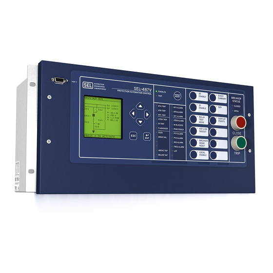
Page 9: Front Panel Display
The rotating display scrolls through the bay screen, alarm points, display points, and metering screens. Each Figure 9 Factory-Default Front-Panel Display and display remains for a user-programmed time (1–15 Pushbuttons Schweitzer Engineering Laboratories, Inc. SEL-487V Data Sheet... - Page 10 Close-up views of the front panel of the SEL-487V are sets can be printed from a laser printer using templates shown in Figure 8, Figure 9, and Figure 10. The front supplied with the relay or hand labeled on supplied blank panel includes a 128 pixel by 128 pixel, 3 in.
-
Page 11: Alarm Points
Alarm Points Auxiliary Trip/Close Pushbuttons and Indicating LEDs You can display messages on the SEL-487V front-panel Optional auxiliary trip and close pushbuttons (see LCD that indicates alarm conditions in the power system. Figure 19 and Figure 20) and indicating LEDs allow The relay uses alarm points to place these messages on breaker control independent of the relay. - Page 12 Harmonic and THD Metering ➤ once per day Accurately measure harmonic current and voltage content up to the 15th harmonic with the SEL-487V Event Reporting and Sequential Harmonic Metering Function. The MET H command Events Recorder (SER) provides harmonic content measurement for individual harmonics from fundamental through the 15th harmonic.
-
Page 13: Sntp Time Synchronization
Frequency Tracking = Y Sequential Events Recorder (SER) A single IRIG-B time-code input synchronizes the SEL-487V time to within ±1 ms of the time-source input. This feature provides a broad perspective of relay A convenient source for this time code is the SEL-2032 element operation. - Page 14 (Set Point 1) published data of contact wear versus interruption levels and operation count. The SEL-487V breaker monitor (Set Point 2) feature compares the breaker manufacturer’s published data to the integrated actual interrupted current and number of operations.
- Page 15 SNTP Ethernet-based simple network time protocol for time synchronization among relays. Control Equations With equations. The SEL-487V is factory set for use without OGIC additional logic in most situations. For complex or Expanded Capabilities and Aliases...
- Page 16 SER, relay element targets, can be used to transfer information IRRORED event data, and more. between the SEL-487V and other system voltage ➤ Communication of synchronized phasor measure- regulation devices to provide enhanced system voltage ment data using either SEL Fast Messaging for and power factor control.
- Page 17 Ethernet option. The Ethernet option allows settings, as well as metering and event reports remotely connection of the SEL-487V to a single or dual LAN using the ASCII interface. Transfer settings files to and (see Figure 18). The integrated Ethernet card supports from the relay via the high-speed Ethernet port with FTP.
- Page 18 Figure 17 SEL-487V HTTP Web Server Settings Screen ➤ IEC 61850 Ethernet IEC 61850 Data Server. The SEL-487V, equipped with embedded IEC 61850 Ethernet protocol, pro- Communications vides data according to predefined logical node objects. As many as six simultaneous client associ- IEC 61850 Ethernet-based communications provide ations are supported by each relay.
-
Page 19: Breaker Control
One board can be added to the 4U chassis, and two additional I/O boards can be added to the 5U chassis. Breaker Control The SEL-487V contains analog voltage inputs for multiple sources and control inputs to indicate both breaker and disconnect position, as well as the logic required to provide breaker control. -
Page 20: Front- And Rear-Panel Diagrams
Front- and Rear-Panel Diagrams i4453a 4U Horizontal Rack Mount With Auxiliary Trip and Close Pushbuttons i4454b 5U Horizontal Panel Mount Figure 19 Typical SEL-487V Horizontal Front-Panel Diagrams SEL-487V Data Sheet Schweitzer Engineering Laboratories, Inc. - Page 21 4U Vertical Rack Mount 5U Vertical Panel Mount With Auxiliary Trip and Close Pushbuttons Figure 20 Typical SEL-487V Vertical Front-Panel Diagrams Schweitzer Engineering Laboratories, Inc. SEL-487V Data Sheet...
- Page 22 4U With INT2 I/O Interface Board 4U With INT4 I/O Interface Board 4U With Main Board and No I/O Interface Board Figure 21 4U Rear-Panel Options SEL-487V Data Sheet Schweitzer Engineering Laboratories, Inc.
-
Page 23: Relay Dimensions
5U Connectorized, With INT3 and INT8 Interface Boards and Ethernet Option Figure 22 5U Connectorized With INT3 and INT8 Interface Boards and Ethernet Option Relay Dimensions Figure 23 SEL-487V Dimensions for Rack- and Panel-Mount Models (Horizontal Mounting Shown; Dimensions Also Apply to Vertical Mounting) Schweitzer Engineering Laboratories, Inc. -
Page 24: Specifications
Rated Insulation 300 Vac Voltage (U 470 Vdc Rated Carry: 6 A continuous carry at 70°C 4 A continuous carry at 85°C Note: DC control signals only. Rated Make: 30 A at 250 Vdc SEL-487V Data Sheet Schweitzer Engineering Laboratories, Inc. - Page 25 Dropout <75 Vdc Ordering Options: 10/100BASE-T 220 Vdc: Pickup 176–264 Vdc; Dropout <132 Vdc Connector Type: RJ45 250 Vdc: Pickup 200–300 Vdc; Ordering Option: 100BASE-FX Fiber-Optic Dropout <150 Vdc Connector Type: Fiber Type: Multimode Schweitzer Engineering Laboratories, Inc. SEL-487V Data Sheet...
- Page 26 Slow Damped Oscillatory, Common and regulations. Differential Mode: ±1.0 kV ±2.5 kV Fast Transient, Common and Differential Mode: ±4.0 kV Electrostatic Discharge IEC 61000-4-2:2008 (ESD): IEEE C37.90.3-2001 Contact: ±8 kV Air Discharge: ±15 kV SEL-487V Data Sheet Schweitzer Engineering Laboratories, Inc.
- Page 27 4, 8, and 32 times per power system cycle Class A Canada ICES-001 (A) / NMB-001 (A) Control Points 32 remote bits 32 local control bits 32 latch bits in protection logic 32 latch bits in automation logic Schweitzer Engineering Laboratories, Inc. SEL-487V Data Sheet...
- Page 28 Time-Delay Accuracy: ±0.1% ± 4.2 ms at 60 Hz Based on maximum of the VA, VB, and VC phase voltages Torque Control: control equation OGIC Pickup Range: 0.25 V–300 V in 0.01 steps SEL-487V Data Sheet Schweitzer Engineering Laboratories, Inc.
- Page 29 Voltage Range: 5–33.5 V factor > ±0.5 at nominal frequency Magnitude Accuracy: ±2.5% ± 1 V Time-Delay Range: 0–16,000 cycles, 0.125 cycle increment Phase Accuracy: ±1.0° Time-Delay Accuracy: ±0.1% of setting, ± 0.125 cycle Schweitzer Engineering Laboratories, Inc. SEL-487V Data Sheet...
- Page 30 VAY, VBY, VCY, VAZ, VBZ, VCZ Pole: ±5% Function: (4-wire wye connected) Compressor/Motor Start Range: 2–300 V (PT) and Run Time: ±1 day Magnitude Accuracy (at Time Since Last 20°C and Nominal Operation: ±1 day Frequency): ±1.2% SEL-487V Data Sheet Schweitzer Engineering Laboratories, Inc.
- Page 31 4 cycle dur. Medium: 1 sample/cycle 176 cycle dur. Slow: 1 sample/64 cycles 4096 cycle dur. Daily: 1 sample/day Indefinite Control Functions (SEL-487V-1) Voltage Control Dead-Band Range: 10.00–300.00 V sec. Dead-Band Control Delay: 1–6000 s Stall-Time Delay: 1–6000 s Power Factor Control Dead-Band Range: 0.01–0.99...
- Page 32 SEL products appearing in this document may be covered by U.S. and Foreign selinc.com • info@selinc.com patents. Schweitzer Engineering Laboratories, Inc. reserves all rights and benefits afforded under federal and international copyright and patent laws in its products, including without lim- itation software, firmware, and documentation.
Need help?
Do you have a question about the SEL-487V and is the answer not in the manual?
Questions and answers