Sign In
Upload
Manuals
Brands
Lenze Manuals
Control Unit
EMF2133IB
Lenze EMF2133IB Manuals
Manuals and User Guides for Lenze EMF2133IB. We have
2
Lenze EMF2133IB manuals available for free PDF download: Communications Manual, Mounting Instructions
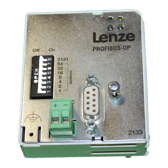
Lenze EMF2133IB Communications Manual (134 pages)
PROFIBUS-DP Communication module
Brand:
Lenze
| Category:
Control Unit
| Size: 0 MB
Table of Contents
Table of Contents
2
1 About this Documentation
5
Document History
6
Conventions Used
7
Terminology Used
8
Notes Used
9
2 Safety Instructions
10
General Safety Information
10
Device− and Application−Specific Safety Instructions
11
Residual Hazards
11
3 Product Description
12
Application as Directed
12
Identification
13
Product Features
14
Connections and Interfaces
15
4 Technical Data
16
General Data
16
Protective Insulation
17
Communication Time
18
Processing Time 820X
18
Processing Time 821X / 822X / 824X / 8200 Vector
19
Processing Time 93XX / Ecsxs
19
Processing Time Drive PLC / 9300 Servo PLC / Ecsxa
19
Dimensions
20
5 Installation
21
Mechanical Installation
22
Electrical Installation
23
Wiring According to EMC (Ce−Typical Drive System)
23
Wiring with a Host (Master)
24
Connection of the PROFIBUS
27
Voltage Supply
28
Cable Cross−Sections and Screw−Tightening Torques
30
6 Commissioning
31
Before Switching on
31
Initial Switch−On
32
Configuring the Host System (Master)
34
Activating the Bus Terminating Resistor
37
Setting the Software Compatibility
37
Preparing the Standard Device for Communication
38
Frequency Inverter 82XX / 8200 Vector
38
93XX Servo Inverter / 9300 Servo PLC
39
Drive PLC
40
Axis Modules Ecsxs / Ecsxa
41
Setting the Node Address
42
Setting Via Code
42
Settings Via DIP Switch
42
Settings by a Master (Class 2)
43
Connecting the Mains Voltage
44
7 Process Data Transfer
45
Lenze Device Control
46
Setpoint Source Selection
46
Process Data Signals for 82XX Frequency Inverters
47
Process Data Signals for 8200 Vector Frequency Inverters
52
Process Data Signal for 9300 Servo Inverters
57
Process Data Signals for 9300 Servo PLC and Drive PLC
63
Process Data Signals for Axis Modules Ecsxs / Ecsxa
67
DRIVECOM Control
68
Provide DRIVECOM Compatibility
68
DRIVECOM State Machine
69
DRIVECOM Control Word
71
DRIVECOM Status Word
73
Bit Control Commands
75
Status Bits
76
Profidrive Control
77
Establishing Profidrive Compatibility
77
Profidrive State Machine
78
Profidrive Control Word
79
Profidrive Status Word
81
8 Parameter Data Transfer
82
Lenze Parameter Sets
83
Parameter Sets for 82XX Controllers
83
Parameter Sets for 8200 Vector Controller
84
Parameter Sets for Controller 93XX
85
Parameter Sets for Drive PLC and Ecsxs / Ecsxa Axis Modules
86
DRIVECOM Parameter Data Channel
87
Addressing of the Parameter Data
87
Addressing of the Lenze Parameters
87
Telegram Structure
87
Error Codes (DRIVECOM)
91
Reading Parameters
92
Writing Parameters
94
Profidrive Parameter Data Channel
96
Profidrive DP−V1
97
Error Codes (Profidrive)
109
Consistent Parameter Data
110
9 Diagnostics
112
LED Status Displays
112
Troubleshooting and Fault Elimination
113
Controller Is Inhibited
113
Checking PROFIBUS
115
Activation of Communication Module
116
Reset Fault (TRIP)
117
Monitoring with Interrupted PROFIBUS Communication
118
Permanent Interruption of Communication
118
Short−Time Interruption of Communication
119
10 Codes
120
Overview
120
Monitoring Codes
122
Diagnostics Codes
124
11 Index Table
125
DRIVECOM Profile Parameter
125
12 Appendix
126
Parallel Operation of AIF and FIF Interfaces
126
Accessories
128
13 Index
129
Advertisement
Lenze EMF2133IB Mounting Instructions (104 pages)
PROFIBUS Communication module
Brand:
Lenze
| Category:
Control Unit
| Size: 0 MB
Table of Contents
Deutsch
7
Table of Contents
7
1 Sicherheitshinweise
8
Definition der Verwendeten Hinweise
8
Restgefahren
9
2 Lieferumfang
10
3 Mechanische Installation
11
4 Elektrische Installation
12
Verdrahtung mit einem Leitrechner
12
EMV-Gerechte Verdrahtung
13
Verdrahtung
14
Spannungsversorgung
16
Belegung der Sub-D-Buchse
18
5 Inbetriebnahme
19
Vor dem Ersten Einschalten
19
Erstes Einschalten
20
Grundgerät zur Kommunikation Vorbereiten
22
Leitsystem Konfigurieren
26
Busabschluss-Widerstand Aktivieren
27
Adressierung
28
Netzspannung Zuschalten
31
Statusanzeige
32
6 Technische Daten
33
Allgemeine Daten und Einsatzbedingungen
33
Schutzisolierung
35
Abmessungen
36
English
41
1 Safety Instructions
42
Definition of Notes Used
42
Residual Hazards
43
2 Scope of Supply
44
3 Mechanical Installation
45
4 Electrical Installation
46
Wiring to a Host
46
Wiring According to EMC
47
Wiring
48
Voltage Supply
50
Sub-D Socket Assignment
52
5 Commissioning
53
Before Switching on
53
Initial Switch-On
54
Preparing the Controller for Communication
55
Configuring the Host
59
Activating the Bus Terminating Resistor
60
Addressing
61
Connecting the Mains Voltage
64
Status Display
65
6 Technical Data
66
General Data and Operating Conditions
66
Protective Insulation
68
Dimensions
69
Français
73
1 Consignes de Sécurité
74
Définition des Conventions Utilisées
74
Dangers Résiduels
75
2 Equipement Livré
76
3 Installation Mécanique
77
4 Installation Électrique
78
Raccordement À un Maître
78
Câblage Conforme CEM
79
Câblage
80
Alimentation
82
Affectation de la Prise Sub-D
84
5 Mise en Service
85
Avant la Première Mise en Service
85
Première Mise en Service
86
Préparation de L'appareil de Base Pour la Communication
88
Configuration du Système Maître
92
Activation de la Résistance D'extrémité de Bus
93
Adressage
94
Mise Sous Tension
97
Affichage D'état
98
6 Spécifications Techniques
99
Caractéristiques Générales Et Conditions D'utilisation
99
Isolement
101
Encombrements
102
Advertisement
Related Products
Lenze EMF2192IB
Lenze L-force Communication ModemCAN EMF2181IB
Lenze EMF2180IB
Lenze EMF2191IB
Lenze L-force CANopen EMF2178IB
Lenze EMB934 Series
Lenze EMB8251-E
Lenze EMB8252-E
Lenze EMB8253-E
Lenze EMZ9374IB
Lenze Categories
DC Drives
Control Unit
Inverter
Engine
Controller
More Lenze Manuals
Login
Sign In
OR
Sign in with Facebook
Sign in with Google
Upload manual
Upload from disk
Upload from URL