Table of Contents
Advertisement
Advertisement
Table of Contents

Related Manuals for Aisin GHP Series


Summary of Contents for Aisin GHP Series
-
Page 3: Table Of Contents
Indice Outdoor Unit (mod. 8 – 10 – 13 HP) ......................5 Technical specifications ........................6 External dimensions ........................... 7 Allowed temperature range ........................ 8 Noise level charateristics........................9 Space required for installation ......................12 Outline diagram of refrigerant piping ....................14 Refrigerant piping installation specifications .................. -
Page 5: Outdoor Unit (Mod. 8 - 10 - 13 Hp)
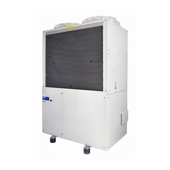
Outdoor Unit (mod. 8 – 10 – 13 HP) 8 HP – AXGP224E1 [N – P] [NATURAL GAS – LPG] 10 HP – AXGP280E1 [N – P] [NATURAL GAS – LPG] 13 HP – AXGP335E1 [N – P] [NATURAL GAS – LPG]... -
Page 6: Technical Specifications
1.1 Technical specifications AXGP224E1 AXGP280E1 AXGP355E1 Model 8 HP 10 HP 13 HP 100% 22,4 28,0 35,5 Rated cooling capacity* 11,2 14,0 17,8 Performace 100% 25,0 31,5 40,0 Rated heating capacity** 12,4 15,5 20,2 Maximum heating capacity*** 26,5 33,5 42,5 Natural gas G20 Type Natural gas G25... -
Page 7: External Dimensions
1.2 External dimensions... -
Page 8: Allowed Temperature Range
1.3 Allowed temperature range Cooling Allowed cooling mode temperature range Outdoor temperature (°C) Heating Campo di applicazione Campo di applicazione Kit zone Kit zone Allowed heating mode Cold fredde fredde in riscaldamento in riscaldamento temperature range district Outdoor temperature (°C) Temperatura aria esterna [°... -
Page 9: Noise Level Charateristics
1.4 Noise level charateristics Global values (dB(A)/m) Front Model Front Rear Right Left AXGP224E1 Detection status: Semi-anechoic room Distance 1 m Height 1 m... - Page 10 Noise level charateristics Global values (dB(A)/m) Front Model Front Rear Right Left AXGP280E1 Detection status: Semi-anechoic room Distance 1 m Height 1 m...
- Page 11 Noise level charateristics Global values (dB(A)/m) Front Model Front Rear Right Left AXGP355E1 Detection status: Semi-anechoic room Distance 1 m Height 1 m...
-
Page 12: Space Required For Installation
1.5 Space required for installation 1) Provide sufficient distance from flammable materials WARNING Install the outdoor unit in the proper distance from flammable items as required by the rel- evant local and national regulations, and technical standards. (See the reference below.) If the distance does not meet the requirements, it could result in a fire. - Page 13 2) Installation space CAUTION The following drawings show the minimum installation space for providing room for intake air and inspection and maintenance operations. Insufficient space could result in injury to the maintenance personnel or damage to the equipment Provide ample space for inspection and maintenance taking into account the refrigerant and fuel gas piping.
-
Page 14: Outline Diagram Of Refrigerant Piping
1.6 Outline diagram of refrigerant piping Flare connections Indoor unit Indoor unit Brazing connections Outdoor unit Branch pipes or helders (sold separatly) Fuel gas pipe R ¾’’ Refrigerant capor line (brazing) Refrigerant liquid pipe (brazing) Condensation water drain port Exhaust gas water drain port 1.7 Refrigerant piping installation specifications Item... -
Page 15: Refrigerant Piping - Selecting Branches And Permissible Lengths
1.8 Refrigerant piping – Selecting branches and permissible lengths CAUTION • Make sure that total extension refrigerant piping lenght is 520 m. or less. • If the refrigerant piping equivalent length exceeds 100 m, use pipes with diameters larger by one rank indicated in “4-3. - Page 16 Selecting branch piping and permissible piping length Line branching Layout example (When 6 indoor units are connected) Note: If there is a height differen- ce between the locations of 10 m 10 m indoor and outdoor units, apply a small “trap pipes” only on the vapor line at least every 10 m as illustrated.
- Page 17 Header branching Layout example (When 6 indoor units are connected) Note: If there is a height differen- ce between the locations of indoor 10 m 10 m and outdoor units, apply a small “trap pipes” only on the vapor line at least every 10 m as illustrated.
- Page 18 Line – Header combined branching Layout example (When 6 indoor units are connected) Note: If there is a height differen- ce between the locations of indoor 10 m 10 m and outdoor units, apply a small “trap pipes” only on the vapor line at least every 10 m as illustrated.
- Page 19 AWS line connection Layout example (When AWS is connected) Note: If there is a height differen- ce between the locations of indoor and 10 m outdoor units, apply a small “trap pipes” only on the vapor line at least every 10 m as illustrated. Permissible Maximum piping length (L) piping...
-
Page 20: Refrigerant Charging
1.9 Refrigerant charging ATTENTION • When charging the refrigerant, accurately measure the length of the piping and charge the proper amount of refrigerant. If the amount of refrigerant is not proper, performance will decline or a breakdown could occur. • After completion of refrigerant charging, write down the installation record on the plate “POINTS FOR INSTALLATION”... -
Page 21: Note For Branch Piping
1.10 Note for branch piping REMIND When connecting the branch pipe, do not bend the main pipe near the connection. If such bending is unavoidable, provide a minimum of 150 mm of straight portion. However, do not use a bent pipe with an external diameter of Ø... -
Page 22: How To Extend Exhaust Pipe
1.11 How to extend exhaust pipe • Use stainless steel or polymer section pipes with a diameter of 80 mm for exhaust pipe extension. • Make sure the pipes for extension can withstand temperatures up to 120° and acid condensed water. ATTENTION •... - Page 23 Extended the exhaust pipe according to the following procedure by referring to the figure below. 1. Remove the exhaust top from the outdoor unit exhaust port. 2. Connect the extra sections sequentially from the outdoor unit side, and extend the exhaust pipe to the desired position following the restriction below.
-
Page 24: Summary Of Electric Wiring Installation
1.12 Summary of electric wiring installation ATTENTION • Use a dedicated branch circuit. Never use the outdoor unit with other appliances on the same circuit. If the outdoor unit and other appliances are used on the same circuit, secondary damage could occur due to breaker tripping. -
Page 25: Wiring Example (Ac 230 V Single Phase)
1.12.2 Wiring example (AC 230 V single phase) -
Page 26: Power Supply Wiring Procedure
1.13 Power supply wiring procedure Wiring instruction 1.13.1... -
Page 27: Wiring Lenght
Wiring lenght 1.13.2 The wiring length of indoor-outdoor and outdoor-outdoor signal wires except the wiring of the remote controller must not exceed the following restriction: • Longest wiring length: 1000 meters • Total wiring length: 2000 meters (When using shielded wires, the total wire length is restricted up to 1500 meters.) SYSTEM EXAMPLE •... -
Page 28: Branch Wiring
Branch wiring 1.13.3 The following 3 wiring methods are acceptable. • SERIES WIRING • BUS WIRING (up to 10 branches, re-branching after the branch is not possible) • STAR WIRING (up to 10 branches, re-branching after the branch is not possible) Note) Although the above figures show the examples using the centralized controller, the same wiring system can be used with other centralized control devices. -
Page 29: Various Function Settings
1.14 Various function settings Address setting method of the indoor and outdoor units The address setting of the indoor and outdoor units is performed automatically. When the centralised remote control is added, set the group address to the indoor units with the standard remote controller. -
Page 30: Outdoor Unit (Mod. 16 - 20 - 25 Hp)
Outdoor unit (mod. 16 – 20 – 25 HP) 16 HP – AWGP450E1 [N – P] [NATURAL GAS – LPG] 20 HP – AWGP560E1 [N – P] [NATURAL GAS - LPG] 25 HP – AWGP710E1 [N – P] [NATURAL GAS - LPG]... -
Page 31: Specifiche Tecniche
2.1 Specifiche tecniche AWGP450E1 AWGP560E1 AWGP710E1 Model 16 HP 20 HP 25 HP 100% 45,0 56,0 71,0 Rated cooling capacity* 22,5 28,0 35,5 Performance 100% 50,0 63,0 80,0 Rated heated capacity** 24,7 30,9 40,0 Maximum heating capacity*** 53,0 67,0 84,0 Natural gas G20 Type Natural gas G25... -
Page 32: External Dimensions
2.2 External dimensions... -
Page 33: Allowed Temperature Range
2.3 Allowed temperature range Cooling Allowed cooling mode temperature range Outdoor temperature (°C) Heating Campo di applicazione Campo di applicazione Kit zone Kit zone Allowed heating mode Cold fredde fredde in riscaldamento in riscaldamento temperature range district Outdoor temperature (°C) Temperatura aria esterna [°... -
Page 34: Noise Level Charateristics
2.4 Noise level charateristics Global values (dB(A)/m) Model Front Rear Right Left AWGP450E1 Detection status: Semi-anechoic room Distance 1 m Height 1 m... - Page 35 Noise level charateristics Global values (dB(A)/m) Model Front Rear Right Left AWGP560E1 Detection status: Semi-anechoic room Distance 1 m Height 1 m...
- Page 36 Noise level charateristics Global values (dB(A)/m) Model Front Rear Right Left AWGP710E1 Detection status: Semi-anechoic room Distance 1 m Height 1 m...
-
Page 37: Space Required For Installation
2.5 Space required for installation Provide sufficient distance from flammable materials WARNING Install the outdoor unit in the proper distance from flammable item sas required by the relevant local and national regulations, and technical standards. (see the reference below). If the distance does not meet the requirements, it could be result in fire. - Page 38 Installation space CAUTION The following drawings show the minimum installation space for providing room for intake air and inspection and maintenance operations. Insufficient space could result in injury to the maintenance personnel or damage to the equipment. Provide ample space for inspection and maintenance taking into account the refrigerant and fuel gas piping.
-
Page 39: Combinations And Capacities Of The Outdoor Units And Indoor Units
2.6 Combinations and capacities of the outdoor units and indoor units Install the indoor units that correspond to indoor air conditioning load. Otherwise, the units frequently repeat start and stop. That could result in breakdown of the units. The number and total capacity of the connected indoor units must be within the CAUTION range shown below. -
Page 40: Outline Diagram Of Refrigerant Piping
2.7 Outline diagram of refrigerant piping 2.7.1 Combined installation... -
Page 41: Stand-Alone Installation
2.7.2 Stand-alone installation... -
Page 42: Refrigerant Piping Installation Specifications
2.8 Refrigerant piping installation specifications 2.8.1 Combined installation Item Refrigerant piping diameter Permissible height Permissible piping (mm)* difference (m) Outdoor unit length (m) Refrigerant Equivalent Outdoor Outdoor unit Vapor line Liquid line length/Actual length unit is higer is lower P450 [16HP] ø... -
Page 43: Reducer Selection For Combined Installation
Reducer selection for combined installation 2.8.3 Item Mark Name Specification Remark 16 HP 20 HP 25 HP D.E. 28,6 – D.I. 31,8 ■ Provided with the Reducer outdoor unit D.I. 31,8 – D.E. 28,6 ■ Vapor line Copper ø 28,6 ■... - Page 44 • Connect the refrigerant piping between the outdoor units to the stop valve as shown in the following figure A or B. otherwise, the refrigerant oil can accumulate in the piping. • Be sure to install the Combinetion Multi connection kit “horizontally” for both vapor and liquid line. Assicurarsi di installare il kit combination multi in posizione orizzontale per entrambe le tubazioni del liquido e del gas.
- Page 45 • Make strait portion of 660 mm. or more before branching of the Combination Multi connection kit. • When the piping length from the Combination Multi connection kit to the outdoor uniti s 2 m. or more, make a rising of 200 mm. or more on vapor piping only at location 2 m. or less the Combination Multi connction kit.
-
Page 46: Refrigerant Piping - Selecting Branch Pipes And Permissible Lengths
2.9 Refrigerant piping – Selecting branch pipes permissible lengths 2.9.1 Combined installation Follow the piping specification shown below when installingnew refrigerant piping. When reusing existing piping, confirm that existing piping meets the pipe specification shown in this manual. CAUTION • Make sure that total extension refrigerant piping length is 520 m. - Page 47 Selecting branch piping and permissible piping length Line branching * When total capacity of connected indoor unit exceed 130% of rated capacity, restrict the permissible piping length (actual length) to 100 m.
- Page 48 Header branching * When total capacity of connected indoor unit exceed 130% of rated capacity, restrict the permissible piping length (actual length) to 100 m.
- Page 49 Line – header combined branching * When total capacity of connected indoor unit exceed 130% of rated capacity, restrict the permissible piping length (actual length) to 100 m.
-
Page 50: Stand Alone Installation
Stand alone installation 2.9.2 Follow the piping specification shown below when installingnew refrigerant piping. When reusing existing piping, confirm that existing piping meets the pipe specification shown in this manual. AVVERTENZA • Make sure that the total extension refrigerant piping legth is 520 m. or less. •... - Page 51 Selecting branch piping and permissible piping length Line branching * When total capacity of connected indoor unit exceed 130% of rated capacity, restrict the permissible piping length (actual length) to 100 m.
- Page 52 Header branching * When total capacity of connected indoor unit exceed 130% of rated capacity, restrict the permissible piping length (actual length) to 100 m.
- Page 53 Line – header combined branching * When total capacity of connected indoor unit exceed 130% of rated capacity, restrict the permissible piping length (actual length) to 100 m.
- Page 54 AWS line connection WARNING • Always refer to AWS installation manual for maintenance clearance and position of the unit. • Always connect AWS to the designed outdoor unit for AWS. • Never exceed the maximum allowed distance between AWS and GHP. Failure in doing so can result in malfunctioning of the units and invalidates the warranty.
-
Page 55: Refrigerant Charging
2.10 Refrigerant charging ATTENTION • When charging the refrigerant, accurately measurament the length of the piping and charge the proper amount of refrigerant. If the amount of refrigerant is not proper, performace will decline or a breakdown could occur. • After completion of refrigerant charging, write down the installation record on the plate “POINTS FOR INSTALLATION”... -
Page 56: Notes For Branching Piping
2.11 Notes for branching piping CAUTION when connecting the branch pipe, do not bend the main pipe near the connection. If such bending is unavoidable, provide a minimum fo 150 mm. Of straight portion. However, do not use a bent pipe with external diameter of ø 28.6 or larger. -
Page 57: How To Extend Exhaust Pipe
For the correct positioning of the exhaust gas line extension kit refer to national regulations or Local regulations. ALWAYS install a reduction (not supplied with the kit exhaust gas line extension) on the end of the exhaust pipe AISIN GHP outdoor unit before installing the kit itself. ATTENTION •... - Page 58 Extended the exhaust pipe according to the following procedure by referring to the figure below. • Remove the exhaust top from the outdoor unit exhaust port. • Connect the extra sections from the outdoor unit side, and extend the exhaust pipe to the desidered position following the restriction below: Total length 15 m...
-
Page 59: Power Supply Wiring Procedure
2.13 Power supply wiring procedure 2.13.1 Wiring instruction combined installation... -
Page 60: Wiring Instruction Stand-Alone Installation
2.13.2 Wiring instruction stand-alone installation... -
Page 61: Summary Of Electric Wiring Installation
2.14 Summary of electric wiring installation ATTENZIONE • Use a dedicated branch circuit. Never use the outdoor unit with other appliances on the same circuit. If the outdoor unit and other appliances are used on the same circuit, secondary damage could occur due to breaker tripping. •... -
Page 62: Wiring Example (Ac 230V Single Phase)
2.14.2 Wiring example (AC 230V single phase) -
Page 63: Direct Expansion Indoor Unit System Wiring (Ac 230V Single Phase)
2.14.4 Air water system wiring (AC 230V single phase) The type of power is always indicated on the nameplate. Always check what kind of power is needed for the proper functioning of the AISIN GHP. Never feed with three-phase current. -
Page 64: Wiring Length
2.15 Wiring length The wiring length of indoor-outdoor signal wires except the wiring of the remote controller must not exceed the following restriction: • Longest wiring length: 1.000 m. • Total wiring length: 2.000 m. (when using shielded wires, the total wire length is restricted up to 1.500 m.) SYSTEM EXEMPLE •... -
Page 65: Branch Wiring
2.16 Branch wiring The following 3 wiring methods are acceptable. • SERIES WIRING • BUS WIRING (up to 10 branches, re-branching after the branchi s not possible) • STAR WIRING (up to 10 branches, re-branching after the branchi s not possible) -
Page 66: Various Function Setting
2.17 Various function setting Address setting method of the indoor and outdoor units The address settind of the outdoor and indoor units is performed automatically. When the centralised remote controller is added, set the group address to the indoor units with the standard remote controller. If the standard remote controller is not installed provide that the service center brings a spare one to set the group address on each one unit. - Page 67 Before beginning the installation of the YOSHI AWS unit, read and fully under stand the contents of this manual. After the installation, always call the local AISIN Authorised Service Centre to perform the outdoor and indoor units commissioning.
- Page 68 INDEX Specifications AWS unit specifications ......................3 Installation prescriptions ....................3 Parts provided........................4 Before installation ........................4 Locally procured parts ....................... 4 Use of water and glycol mixture ................... 5 Installation ..........................5 Selecting the location for installation ................. 5 External dimensions, hydraulic and refrigerant gas connections ........
- Page 69 With Pump/Without Pump 164/153 204/177 Connectable GHP outdoor units Each AWS unit can be connected with a single AISIN GHP outdoor unit ∗ Rated cooling capacity is measured according to the following conditions: water outlet temperature 7°C; outdoor temperature 35°C DB ∗∗...
- Page 70 2 Before installation Parts provided The following parts are provided with the YOSHI AWS unit. Name Installation Control box 2” Y-shape filter 2” brass nipless manual wiring diagram For water pipe [gaskets] [gaskets] where provided Quantity 1 - [2] 2 - [2] Inside the Location Inside the unit near the water connections...
- Page 71 3 Use of water and glycol mixture Use mixtures of water and antifreeze fluid to lower the freezing point of water. The liquid most commonly used as antifreeze is ethylene glycol. The table shows the reduction factors of the cooling capacity and the capacity of the pump of the AWS as a function of the water temperature and percentage by weight of glycol in the mixture.
- Page 72 4.2 External dimensions, hydraulic and refrigerant gas connections The table below shows the diameters of the water connections, refrigerant, piping diameters and their position in the various models of AWS. TECHNICAL DATA Water connections Inch 2 or higher Anti vibration joints should be foreseen at the water connections in some kind of installation layouts. Water pipe connections Inch The supplied Y strainer must always be installed with a minimum distance of 50 cm from the...
- Page 73 4.3 Installation space Clearances for maintenance and inspection operations are described in the tables below. CAUTION • The minimum installation spaces are necessary to provide room for air circulation, inspection and maintenance of the AWS unit. Failure to observe this prescription could result in injury to the maintenance personnel and damage to the unit.
- Page 74 WARNING All the welding operations on the AWS – GHP refrigerant gas piping must be always performed in accordance with instructions and prescriptions mentioned in the AISIN GHP installation manual (brazing with nitrogen flow). Failure to observe this prescription makes the warranty no longer valid and could result in malfunction...
- Page 75 It is forbidden to connect direct expansion indoor units and YOSHI AWS to a single AISIN GHP outdoor unit simultaneously. The YOSHI AWS can be only connected to a specific AISIN GHP outdoor unit for AWS with the same capacity.
- Page 76 L2: Liquid pipe Ø 12.7 total length (m) L3: Liquid pipe Ø 9.52 total length (m) The value of the variable parameter Q depends on the capacity of the AISIN GHP outdoor unit connected to the YOSHI AWS. Use the table below as reference.
- Page 77 6 Electric wire installation 5.4 Cooling mode The refrigerant (R410A) processed by the GHP flows through electronic expansion valve and enters the lower part of the AWS unit heat exchanger at low pressure. The gas evaporates in the plate heat exchanger by taking heat from the counter current water flow. It goes back to the GHP as overheated steam.
- Page 78 NEVER switch on the power supply before the final commissioning is performed by the AISIN Authorised Service Centre. Failure to observe this prescription makes the warranty no longer valid and could result in malfunction and/or damage to the YOSHI AWS unit.
- Page 79 CAP-/CAP+: Current signal power control 4-20 mA DC CONTACT H/C: Heat/Cool selection signal REM1: Heat/Cool remote selection 0-12-12: Power supply control panel "controller plus" (12V) F1-F2: GHP AISIN - AWS YOSHI communication 485+/485-: Modbus CANH/CANL/CANG: Communication line panel "controller plus" Q1-Q2: Outdoor units communication. "Installation GHPCHK: General alarm signal outdoor unit GHP combined"...
- Page 80 8 AWS Accessories 8.1 Controller Plus: Control Panel and Probe Temperature Buffer Tank 8.1.1 Control panel Control panel for the remote management of the AWS with which is possible to control and management of a single module from a remote location. The shielded cable connecting the panel to the module has a maximum length of 60 meters.
- Page 81 The YOSHI AWS control panel is represented below. In case of AISIN GHP outdoor unit malfunction, the error code will be displayed on the remote controller fitted in the YOSHI AWS control panel. Check the failure type on the AISIN GHP installation manual.
- Page 82 10 AWS Set Point Adjustment 10.1 Control panel The unit AWS YOSHI has the possibility to vary the capacity delivered, in a range between 25% and 100% of rated power, as a function of the return water temperature on the primary circuit. The modulation of the capacity is adjusted according to a proportional band.
- Page 83 Example modulation in cooling: The set point temperature in cooling, ie the parameter "Tset cool", may vary in a range between 6°C and 15°C. The factory settings are: Tset cool= 8°C; Modulation Range = 5°C AWS Capacity Tset cool [°C] Modulation Max.
- Page 84 11.1 Central storage tank installation This layout is recommended by the manufacturer for fan-coil installations. to optimise the operation of the AISIN GHP. When choosing this layout always make sure that the water flow of the primary and the secondary circuits are balanced.
- Page 85 11.4 HVAC installation layout AWS E1...
- Page 86 11.5 HVAC installation E1 with proportional distribution of consumption...
- Page 87 11.6 HVAC installation AWS E1J variable flow rate no hydraulic separator (AHU)
- Page 88 11.7 HVAC installation AWS E1J variable flow rate with hydraulic separator (fan coil)
- Page 89 The heat pump is about to Maintenance period reach the 10.000 hours of A13S1 • Contact the service centre Aisin warning operation. Need for routine maintenance. The heat pump has • Reset the hours of operation (See Maintenance period reached 10.000 hours of...
- Page 90 the water temperature • Check water circulation and make sure Winter antifreeze inside the AWS dropped A15S1 the unit is not exposed to severe protection below the minimum outdoor conditions. threshold • Check T1T2 setting GHP starting failure A18S1 • Check wiring 15 - 16 •...
- Page 91 The table below shows all the error codes displayed on the remote controller fitted in the AWS control panel. In case of malfunction contact the AISIN Authorised Service Centre that usually maintains the GHP outdoor unit. Blinking indication (ON doesn’t blink)
- Page 92 Blinking indication (ON doesn’t blink) outdoor Type of failure (OFF led off) Possible cause unit Error code Error TEST Unit display code ON/OFF Disp. • 91-0 Compressor discharge temperature too high (>120°C) Operation failure • 87-0,2 Compressor intake temperature too high (> 40°C) •...
- Page 93 NOTE ………………………………………………………………………………………….. ………………………………………………………………………………………….. ………………………………………………………………………………………….. ………………………………………………………………………………………….. ………………………………………………………………………………………….. ………………………………………………………………………………………….. ………………………………………………………………………………………….. ………………………………………………………………………………………….. ………………………………………………………………………………………….. ………………………………………………………………………………………….. ………………………………………………………………………………………….. ………………………………………………………………………………………….. ………………………………………………………………………………………….. ………………………………………………………………………………………….. ………………………………………………………………………………………….. ………………………………………………………………………………………….. ………………………………………………………………………………………….. ………………………………………………………………………………………….. ………………………………………………………………………………………….. ………………………………………………………………………………………….. …………………………………………………………………………………………..
- Page 94 ………………………………………………………………………………………….. ………………………………………………………………………………………….. ………………………………………………………………………………………….. ………………………………………………………………………………………….. ………………………………………………………………………………………….. ………………………………………………………………………………………….. ………………………………………………………………………………………….. ………………………………………………………………………………………….. ………………………………………………………………………………………….. ………………………………………………………………………………………….. ………………………………………………………………………………………….. ………………………………………………………………………………………….. ………………………………………………………………………………………….. ………………………………………………………………………………………….. ………………………………………………………………………………………….. ………………………………………………………………………………………….. ………………………………………………………………………………………….. ………………………………………………………………………………………….. ………………………………………………………………………………………….. ………………………………………………………………………………………….. …………………………………………………………………………………………..
- Page 97 Before beginning the installation of the YOSHI AWS unit, read and fully under stand the contents of this manual. After the installation, always call the local AISIN Authorised Service Centre to perform the outdoor and indoor units commissioning.
- Page 98 INDEX Specifications AWS unit specifications ...................... 3 Installation prescriptions ....................3 Before installation........................ 4 Parts provided........................4 Locally procured parts ....................... 4 Use of water and glycol mixture ..................5 Installation ..........................5 Selecting the location for installation ................. 5 External dimensions, hydraulic and refrigerant gas connections ........
- Page 99 1 AWS unit specifications AWS 40 HP – E1J AWS 50 HP – E1J TWIN unit 16+16 HP 16+20 HP 20+20 HP 16+25 HP 20+25 HP 25+25 HP Capacity code of the connected GHP outdoor unit P900 P1010 P1120 P1160 P1270 P1420 82,0...
- Page 100 2 Before installation Parts provided The following parts are provided with the YOSHI AWS unit. Name Installation Control box 2” Y-shape filter for water DN 65 flanges EN 1092 manual wiring diagram pipe [gaskets] [gaskests] where provided Quantity 1 - [2] 2 –...
- Page 101 3 Use of water and glycol mixture Use mixtures of water and antifreeze fluid to lower the freezing point of water. The liquid most commonly used as antifreeze is ethylene glycol. The table shows the reduction factors of the cooling capacity and the capacity of the pump of the AWS as a function of the water temperature and percentage by weight of glycol in the mixture.
- Page 102 4.2 External dimensions, hydraulic and refrigerant gas connections The table below shows the diameters of the water connections, refrigerant, piping diameters and their position in the various models of AWS. TWIN UNIT REFRIGERANT WATER AND REFRIGERANT GAS CONNECTIONS Water connections Inch The uniti s supplied with DN 65 (EN 1092 1/13) flanges 2,5 or higher...
- Page 103 4.3 Installation space Clearances for maintenance and inspection operations are described in the tables below. CAUTION • The minimum installation spaces are necessary to provide room for air circulation, inspection and maintenance of the AWS unit. Failure to observe this prescription could result in injury to the maintenance personnel and damage to the unit.
- Page 104 WARNING All the welding operations on the AWS – GHP refrigerant gas piping must be always performed in accordance with instructions and prescriptions mentioned in the AISIN GHP installation manual (brazing with nitrogen flow). Failure to observe this prescription makes the warranty no longer valid and could result in malfunction...
- Page 105 It is forbidden to connect direct expansion indoor units and YOSHI AWS to a single AISIN GHP outdoor unit simultaneously. The YOSHI AWS can be only connected to a specific AISIN GHP outdoor unit for AWS with the same capacity.
- Page 106 The refrigerant extra charge must be done in accordance with the procedures described in the AISIN GHP installation manual. Failure to observe this prescription makes the warranty no longer no longer valid and could result in malfunctioning of the YOSHI AWS unit.
- Page 107 6 Refrigerant circuit and hydraulic circuit 6.1 Cooling mode The refrigerant (R410A) processed by the GHP flows through electronic expansion valve and enters the lower part of the AWS unit heat exchanger at low pressure. The gas evaporates in the plate heat exchanger by taking heat from the counter current water flow.
- Page 108 NEVER switch on the power supply before the final commissioning is performed by the AISIN Authorised Service Centre. Failure to observe this prescription makes the warranty no longer valid and could result in malfunction and/or damage to the YOSHI AWS unit.
- Page 109 7.2 Detailed wiring diagram...
- Page 110 8 AWS Accessories 8.1 Controller Plus: Control Panel and Probe Temperature Buffer Tank 8.1.1 Control panel Control panel for the remote management of the AWS with which is possible to control and management of a single module from a remote location. The shielded cable connecting the panel to the module has a maximum length of 60 meters.
- Page 111 The YOSHI AWS control panel is represented below. In case of AISIN GHP outdoor unit malfunction, the error code will be displayed on the remote controller fitted in the YOSHI AWS control panel. Check the failure type on the AISIN GHP installation manual.
- Page 112 10 AWS Set Point Adjustment 10.1 Control panel The unit AWS YOSHI has the possibility to vary the capacity delivered, in a range between 13% and 100% of rated power, as a function of the return water temperature on the primary circuit. The modulation of the capacity is adjusted according to a proportional band.
- Page 113 Example modulation in cooling: The set point temperature in cooling, ie the parameter "Tset cool", may vary in a range between 6°C and 15°C. The factory settings are: Tset cool= 8°C; Modulation Range = 5°C AWS Capacity Tset cool [°C] Modulation Max.
- Page 114 11.1 Central storage tank installation This layout is recommended by the manufacturer for fan-coil installations. to optimise the operation of the AISIN GHP. When choosing this layout always make sure that the water flow of the primary and the secondary circuits are balanced.
- Page 115 11.4 HVAC installation AWS E1J TWIN...
- Page 116 11.5 HVAC installation E1J TWIN proportional distribution of consumption...
- Page 117 11.6 HVAC installation AWS E1J TWIN variable flow rate no hydraulic separator (AHU)
- Page 118 11.7 HVAC installation AWS E1J TWIN variable flow rate with hydraulic separator (fan coil)
- Page 119 Use the Carel display. Press "help" Expansion valve driver A8S1 and check which component is in alarm 1 alarm The heat pump is about to Maintenance period reach the 10.000 hours of A13S1 • Contact the service centre Aisin warning operation. Need for routine maintenance.
- Page 120 The heat pump has • Reset the hours of operation (See Maintenance period reached 10.000 hours of A14S1 page 82, service manual paragraph alarm operation. Need for 13.3 "Reset hours of operation"). routine maintenance. • Check the code displayed on the GHP.
- Page 121 The table below shows all the error codes displayed on the remote controller fitted in the AWS control panel. In case of malfunction contact the AISIN Authorised Service Centre that usually maintains the GHP outdoor unit. Blinking indication (ON doesn’t blink)
- Page 122 Blinking indication (ON doesn’t blink) outdoor Type of failure (OFF led off) Possible cause unit Error code Error TEST Unit display code ON/OFF Disp. • 91-0 Compressor discharge temperature too high (>120°C) Operation failure • 87-0,2 Compressor intake temperature too high (> 40°C) •...
- Page 123 NOTE ………………………………………………………………………………………….. ………………………………………………………………………………………….. ………………………………………………………………………………………….. ………………………………………………………………………………………….. ………………………………………………………………………………………….. ………………………………………………………………………………………….. ………………………………………………………………………………………….. ………………………………………………………………………………………….. ………………………………………………………………………………………….. ………………………………………………………………………………………….. ………………………………………………………………………………………….. ………………………………………………………………………………………….. ………………………………………………………………………………………….. ………………………………………………………………………………………….. ………………………………………………………………………………………….. ………………………………………………………………………………………….. ………………………………………………………………………………………….. ………………………………………………………………………………………….. ………………………………………………………………………………………….. ………………………………………………………………………………………….. …………………………………………………………………………………………..
- Page 124 ………………………………………………………………………………………….. ………………………………………………………………………………………….. ………………………………………………………………………………………….. ………………………………………………………………………………………….. ………………………………………………………………………………………….. ………………………………………………………………………………………….. ………………………………………………………………………………………….. ………………………………………………………………………………………….. ………………………………………………………………………………………….. ………………………………………………………………………………………….. ………………………………………………………………………………………….. ………………………………………………………………………………………….. ………………………………………………………………………………………….. ………………………………………………………………………………………….. ………………………………………………………………………………………….. ………………………………………………………………………………………….. ………………………………………………………………………………………….. ………………………………………………………………………………………….. ………………………………………………………………………………………….. ………………………………………………………………………………………….. ………………………………………………………………………………………..
Need help?
Do you have a question about the GHP Series and is the answer not in the manual?
Questions and answers