Advertisement
Table of Contents
- 1 Table of Contents
- 2 Safety Considerations
- 3 What to Do before Operation
- 4 Operation Procedure
- 5 Operation Range
- 6 Optimum Operation
- 7 Recommendation of Maintenance
- 8 Additional Items of Information to Review
- 9 Trouble Shooting
- 10 Refarence Information
- 11 After Sale Service
- 12 Warranties and Liabilities
- Download this manual
WARNING: If the information in these instructions is not followed
exactly, a fire or explosion may result causing property damage,
personal injury or loss of life.
READ THESE OPERATING INSTRUCTIONS CAREFULLY BEFORE USING THE UNIT.
Follow the safety considerations listed in this manual.
Keep this Operation Manual in a handy place for future reference.
Upon change of ownership, transfer this manual to the equipment owner.
Read this manual along with the Maintenance Instruction of the indoor unit.
This manual should be stored along with the Maintenance Instruction.
Aisin Gas Heat Pump Air Conditioner
Outdoor Unit
OPERATION MANUAL
Applicable models
AXGP096E1NHS
AWGP180E1NHS
Advertisement
Table of Contents

Related Manuals for Aisin AXGP096E1NHS


Summary of Contents for Aisin AXGP096E1NHS
- Page 1 WARNING: If the information in these instructions is not followed exactly, a fire or explosion may result causing property damage, personal injury or loss of life. OPERATION MANUAL Aisin Gas Heat Pump Air Conditioner Applicable models AXGP096E1NHS AWGP180E1NHS Outdoor Unit READ THESE OPERATING INSTRUCTIONS CAREFULLY BEFORE USING THE UNIT.
-
Page 2: Table Of Contents
CONTENTS DANGER 1. SAFETY CONSIDERATIONS .......2 2. WHAT TO DO BEFORE OPERATION..8 Do not install the unit yourself. Improper installation may result in water 3. OPERATION RANGE........14 4. OPERATION PROCEDURE......14 leakage, electric shock, a fire or other hazards. Ask your dealer to carry out the 5. - Page 3 When installing the unit in a small room, Do not dismantle, modify or repair the take measures to keep refrigerant unit by yourself. concentration from exceeding allowable Improper repair and maintenance may safety limits in case of refrigerant result in water leakage, electrical shock, a leakage.
- Page 4 Never remove the fan guard of the unit. WARNING Since the fan rotates at high speed during operation, it may cause injury. Do not expose your body directly to the Turn off all electrical power before doing cold or warm air flow for a long time. Do not cool or heat the room too much.
- Page 5 Do not touch the outdoor unit exhaust Never pull or twist the electric wire of the pipe. remote controller. May cause severe burns. The wiring may be disconnected and cause electric leakage, or cause the unit to Do not leave animals and plants in malfunction.
- Page 6 Do not place the controller near water Location for installation splashes. Make sure that the unit is installed in a Water entering the controller may cause sufficiently ventilated area and not electric shock or damage the internal surrounded by obstacles. electronic parts.
- Page 7 Do not block the air inlet or air outlet of the Drain piping work unit. Make sure that the drainpipe is installed Doing so may lower the performance of the air properly to drain water. conditioner or cause malfunction. If no water is discharged from the drainpipe while If any oil or coolant leaks from the outdoor the system is in the cooling mode, the drainpipe unit, it may cause malfunction or secondary...
-
Page 8: What To Do Before Operation
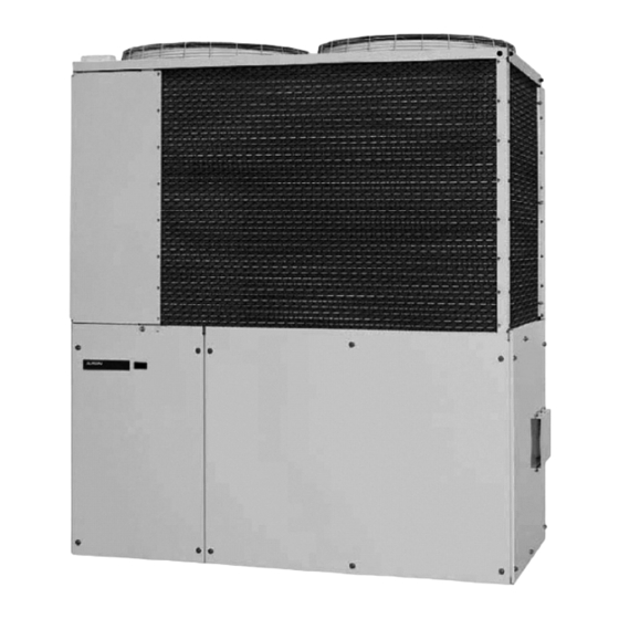
2. Indoor unit 3. Remote controller 4. Inlet air Remote Controller 5. Outlet air 6. COOL/HEAT selector (Above figure shows systems with changeover remote control switches) Outdoor unit • AXGP096E1NHS • AWGP180E1NHS Mode On/Off Menu Cancel Speed 7. Air outlet (Fan) ABRC1D71 Fig . - Page 9 User’s Selectable Languages Operation ● Display the main menu screen. by pressing Main Menu Menu button. Configuration Current Settings Clock & Calendar ● Press buttons to select Daylight Saving Time Language Language on the main menu screen Setting and press the Menu/OK button. ●...
- Page 10 Cool/heat selector FAN ONLY/AIR CONDITIONING SELECTOR SWITCH Set the switch to “ ” for fan only operation or to “ ” for heating or cooling operation. COOL/HEAT CHANGEOVER SWITCH Set the switch to “ ” for cooling or to “ ”...
- Page 11 Names and Functions Liquid Crystal Display ● Two types of liquid crystal display (LCD) are available. The standard display is set by default. ● Detailed display can be selected in the main menu. ● The displayed contents of the screen vary with the operation mode of the indoor unit model. (The following display will appear when the indoor unit is in automatic operation.) Standard display 10.
- Page 12 Names and Functions Operation mode “Error: Push Menu button” “Warning: Push Menu button” ● Used to display the current operation ● Displayed if an error or warning is detected mode: Cool, Heat, Vent, Fan, Dry or Auto. (see page 37). “Time to clean filter”...
- Page 13 Setback “ ” SETBACK ● The setback icon flashes when the unit is turned on under the setback control. Air Flow Direction “ ” ● Displayed when the air flow direction and swing are set (see page 20). ● If the connected indoor unit model does not include oscillating louvers this item is not displayed.
-
Page 14: Operation Range
3. OPERATION RANGE Use the system in the following temperature and humidity ranges for safe and effective operations. COOLING HEATING outdoor temperature 23°~130°FDB 14°~77°FWB indoor temperature 57°~75°FWB 50°~82°FDB indoor humidity 80%* *To avoid condensation and water dripping out the unit. If the temperature or the humidity is beyond these conditions, safety devices will work and the system will not operate. - Page 15 4-1 COOLING/HEATING AND FAN ONLY OPERATION Basic Operation Cool/Heat/Auto/Fan Operation (SkyAir and VRV) Operation procedure Operation status button How to follow the operation manual display Explains the sequence of operation for the remote controller. Displays the location of Operate the buttons according to buttons to be operated.
- Page 16 Basic Operation ● Press On/Off button. The Operation status lamp (green) will On/Off illuminate and the system will start operating. ● The setpoint will increase by 1°F (or 1°C) when button is pressed Cool Set to Cool and decrease by 1°F (or 1°C) when button is pressed.
- Page 17 ● When the On/Off button is pressed again, the system will stop operating On/Off and the operation status lamp will turn off. When the system is stopped while in the heating mode, the fan will continue to operate for approximately one minute to remove residual heat from the indoor unit.
- Page 18 Basic Operation Operation ● Press the Mode button several times until the Dry mode is selected. The dry mode may not be available depending on the type of indoor unit. ● Press On/Off button. The Operation status lamp (green) will On/Off illuminate and the system will start operating.
- Page 19 Characteristic of Dry mode The Dry mode dehumidifies the space at reduced cooling capacity to prevent the room temperature from dropping to uncomfortable levels.
- Page 20 4-3 ADJUSTING THE AIR FLOW DIRECTION Menu Options Air Flow Direction Configuring Air Flow Direction Operation ● Display the main menu screen. Main Menu Air Flow Direction by pressing Menu button. Ventilation Schedule ● Press buttons to select Off Timer Celsius / Fahrenleit Maintenance Information AIR FLOW DIRECTION...
- Page 21 ● Pressing buttons changes the Air Flow Direction setting to (in order) Swing Swing Position 0 Position 1 Setting Left/right direction Position 2 Position 3 , and Air Flow Direction Position 4 Swing ● Selecting Swing will cause the air flow direction louver to oscillate Setting back and forth.
- Page 22 Menu Options Operational Details and Functions There are two types of air flow direction settings. Air flow direction swing Air flow direction The louvers automatically oscillate up You can select from one of five fixed and down. directions. (This has no relation to the angle of the louvers.) Indoor unit Indoor unit...
- Page 23 4-4 SETTING THE COOL/HEAT MASTER CONTROLLER Basic Operation (VRV only) Setting Changes See page 25 for an explanation of the cool/heat master controller. ● Press the Operation Mode Selector button on the remote controller of the cool/heat Cool Set to Cool master for at least four seconds.
- Page 24 Basic Operation ● Press the Mode button on the remote controller of the indoor unit designated Cool Set to Cool as the cool/heat master controller (the remote controller not displaying the Return Setting icon) repeatedly until the desired MASTER CONTROLLED mode is selected.
- Page 25 Precautions for Selecting the Cool / Heat Master Controller ● The cool/heat master controller must be set for a single indoor unit in the following applications (2-Pipe Heat Pump System) A number of indoor units are connected to a single outdoor unit. Set any one of the indoor units as the cool/heat master controller.
- Page 26 4-5 MENU OPTIONS Auto mode Using information from the air conditioner (cool, heat, fan, and setpoint) and the energy recovery ventilator unit (indoor and outdoor temperatures), the ventilation mode is automatically changed between ERV and Bypass. ERV mode Outside air is passed through the ERV core and is supplied to the conditioned space.
- Page 27 Daily Patterns Operation ● The schedule screen will appear. Schedule Enable/Disable ● Press buttons to Daily Patterns Settings select Daily Patterns on the schedule screen. Setting The daily patterns screen will appear when the Menu/OK button is pressed. ● Press buttons to Schedule Daily Patterns...
- Page 28 Menu Options Settings Operation ● The schedule screen will appear. Schedule Enable/Disable ● Press buttons to select Settings Daily Patterns Settings on the schedule screen. The settings screen will appear when Setting the Menu/OK button is pressed. ● Press buttons to select the day to Schedule Time Cool...
- Page 29 ● Press the buttons to move the Schedule Time Cool Heat highlighted item and press buttons – 6 :00 – – – – – – :– – – – – – to configure ON/OFF/-- settings. – – :– – – – –...
- Page 30 Menu Options ● Press buttons to select “Yes” on the Schedule Save the settings? confirmation screen. Pressing the Menu/OK button confirms the settings for each day and takes you Setting back to the main menu screen. Enabling or disabling the schedule Operation ●...
- Page 31 Off Timer Configuring and Confirming the Off Timer settings Operation ● Display the main menu screen. Main Menu by pressing Menu button. Air Flow Direction Ventilation Schedule ● Press buttons to select the Off Timer Celsius / Fahrenheit Off Timer on the main menu screen.
- Page 32 Menu Options Enabling or disabling the off timer Operation ● Navigate to the off timer screen. Off Timer Enable/Disable (See page 31.) Settings ● Press buttons to select Enable/Disable on the off timer screen. Setting Press Menu/OK button to display the enable/disable screen.
-
Page 33: Optimum Operation
4-6 PRECAUTIONS FOR GROUP CONTROL • Keep the indoor unit and remote controller at least 3.5ft. away from televisions, radios, stereos, and SYSTEM OR 2 REMOTE CONTROLLER other similar equipment. CONTROL SYSTEM Failure to do so may cause static or distorted pic- This system provides 2 other control systems besides tures. -
Page 34: Additional Items Of Information To Review
7-3 COOL/HEAT CANNOT BE CHANGED See the Maintenance Instruction attached to the indoor unit for details on how to clean it. OVER Close the valve of the fuel gas. • When the display shows “ ” . It shows that this is a sub remote controller. Refer Turn off the power to the chapter "4-4 SETTING THE COOL/HEAT •... - Page 35 on cleaning the unit. This operation requires a This is the noise of refrigerant caused by flow stop qualified service person. or flow change. • Immediately after the cooling operation stops 7-9 DUST COMES OUT OF THE UNIT when the room temperature and humidity are •...
-
Page 36: Trouble Shooting
8. TROUBLE SHOOTING If it is not possible to fix the problem yourself after checking all the above items, contact your If one of the following malfunctions occurs, take dealer. the measures shown below and contact your Let the dealer know of the symptoms, system dealer. -
Page 37: Refarence Information
9. REFERENCE INFORMATION 9-1. ERROR CODE DISPLAY Contact your dealer in the following cases Operation ● If an error occurs, either one of the following items will flash in the basic screen. Cool Set to Cool “Error: Push Menu button” Operation status The operation lamp will flash. - Page 38 9-2. ERROR CODE LIST System unset/incorrect wiring System failure Error O.U., EEPROM failure Description code O.U., EEPROM model code failure I.U., External protection activation O.U., Programming unmatched I.U., Control board assy EEPROM setting error O.U., Main-engine microcomputer transmission failure I.U., Abnormal drain water level O.U., I/F main microcomputer transmission failure I.U., Fan lock O.U., Refrigerant high pressure failure 2...
-
Page 39: Warranties And Liabilities
This system is warranted by your dealer or distribu- O.U., Compressor discharge temperature sensor 3 short tor, and not by Aisin Seiki CO., LTD or any of its affil- circuit iated companies, including but not limited to Aisin O.U., Compressor discharge temperature sensor 4 short World Corp. - Page 40 11-2. Maintenance Information Displaying the service contact and model information Operation ● Display the main menu screen. Main Menu Air Flow Direction by pressing Menu button. Ventilation Schedule ● Press buttons to select Off Timer Celsius / Fahrenheit Maintenance Information on the main Maintenance Information Setting...
- Page 41 As the non-road SI engine owner, you are responsible for the performance of the required maintenance designated by AISIN. AISIN recommends that you retain all receipts covering maintenance on your engine, but AISIN cannot deny warranty solely for the lack of receipts or your failure to ensure the performance of all scheduled maintenance.
- Page 42 624091-80930 Distributed by: AISIN WORLD CORP OF AMERICA, INC 46501 Commerce Center Drive, Plymouth, MI 48170 U.S.A. It is firmly prohibited to copy, distribute, reproduce, and transmit publicly (including making it electronically available) any of the contents of this manual without permission.
Need help?
Do you have a question about the AXGP096E1NHS and is the answer not in the manual?
Questions and answers