Table of Contents
Advertisement
Quick Links
NoWire Model 2100 Installation and Operation Manual
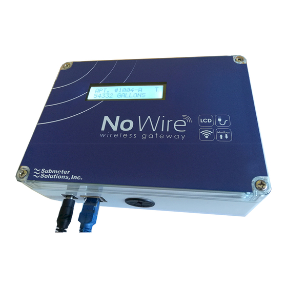
NoWire Model 2100 – Wireless Gateway
(wireless digital points for meters and industrial equipment)
Submeter Solutions, Inc.
Note: The following manual is for the previous version
NoWire 1100. The operation for NoWire 2100 is
generally the same. See section 11 for specifics about
NoWire 2100.
NoWire Model 2100
Submeter Solutions, Inc., 888-64METER
Page 1
Advertisement
Table of Contents

Summary of Contents for Submeter Solution NoWire 2100
- Page 1 (wireless digital points for meters and industrial equipment) Submeter Solutions, Inc. Note: The following manual is for the previous version NoWire 1100. The operation for NoWire 2100 is generally the same. See section 11 for specifics about NoWire 2100. NoWire Model 2100 Submeter Solutions, Inc., 888-64METER...
-
Page 2: Table Of Contents
NoWire Model 2100 Installation and Operation Manual Installation and Operation Manual Table of Contents: Overview ............................... 4 Warnings ............................... 4 NoWire Quick Start ..........................4 Configuring a Wireless Input Pulse Meter ..................4 Configuring a Wired Input Pulse Meter ..................6 NoWire Circuit Board .......................... - Page 3 Install the transmitters ......................21 NoWire Specifications ......................... 25 General Specifications ......................... 25 Wireless Specifications ....................... 25 Copyright Information ........................26 NoWire 2100 Specifics ........................27 11.1 Features different from NoWire 1100 ..................27 11.1.1 Ethernet and Wifi ........................ 27 11.1.2...
-
Page 4: Overview
NoWire Model 2100 Installation and Operation Manual 1 Overview The NoWire Model 1100 provides a wireless link for digital input/output signals. 1. Display readings wirelessly from up to 32 water, gas, and electric meters or run-time sensors via a wireless connection to your meter’s digital pulse output. 2. - Page 5 NoWire Model 2100 Installation and Operation Manual CHANGE NEXT Pressing NEXT will rotate through the various menus. It rotates through the System Items, the 32 Wireless Inputs, the 4 Wired Pulse Inputs, and the 4 Wired Pulse Outputs. Press NEXT once to get to Wireless Input #1. Once there, press CHANGE to setup Wireless Input #1.
-
Page 6: Configuring A Wired Input Pulse Meter
NoWire Model 2100 Installation and Operation Manual 5. Open the case of the EN1501 pulse transmitter by pressing in on the right side that has the small hole. Press the reset button to assign the transmitter. Close the transmitter case. Reset Button This screen indicates when the transmitter reset signal was received. - Page 7 NoWire Model 2100 Installation and Operation Manual NEXT, CHANGE NEXT… Pressing NEXT will rotate through the various menus. It rotates through the System Items, the 32 Wireless Inputs, the 4 Wired Pulse Inputs, and the 4 Wired Pulse Outputs. Press NEXT 31 times will land you on the Pulse Input #1 setup menu item.
-
Page 8: Nowire Circuit Board
NoWire Model 2100 Installation and Operation Manual 4 NoWire Circuit Board 1. 12VDC External power connection, V+ : 12VDC, V- : Ground. 2. 4 Wired Pulse Input connections. P1 & P2 are the positive terminal and share PG as the negative (ground) terminal. -
Page 9: Installation Checklist
NoWire Model 2100 Installation and Operation Manual 10. Pulse Output jumpers. Allows for output connections to power and ground for making powered outputs (voiding optical isolation). Output point jumpers to the right: Pulse Output is optically isolated and non-powered. Output point jumpers to the left: Pulse Output is connected to NoWire power and ground for creating a non-isolated 5V powered output. -
Page 10: Attach Optional External Wiring To Nowire
NoWire Model 2100 Installation and Operation Manual o Locate near a 120V outlet where the NoWire power supply will be plugged in. o Allow room for conduit bends and runs that connect to the bottom of the NoWire enclosure. (if required for application) o Locate away from other equipment per your local electrical codes. -
Page 11: Setup Menus Operation
NoWire Model 2100 Installation and Operation Manual connections are complete to NoWire and you have double checked all your other wiring connections to NoWire, plug in the 12VDC power supply to the 120V outlet. 7 Setup Menus Operation 7.1 Meter data display and setup menus NEXT CHANGE (if valid) -
Page 12: System Items Menu
NoWire Model 2100 Installation and Operation Manual 7.2 System Items menu NoWire Firmware Version. NEXT Change the current time. CHANGE to edit NEXT Change the current date. CHANGE to edit NEXT Change whether the date is displayed in 12 hour format (5:43pm) or 24 CHANGE to edit hour format (17:43). -
Page 13: Wireless Input Menu
NoWire Model 2100 Installation and Operation Manual 7.3 Wireless Input menu CHANGE to edit Change to yes if you wish this wireless input point to be displayed in the rotating meter reading screens once you exit the setup menus. NEXT Change the wireless input point description that is displayed in the CHANGE to edit rotating meter reading screens. -
Page 14: Wired Pulse Input Menu
NoWire Model 2100 Installation and Operation Manual Displays the ID of the transmitter assigned to this wireless input. Status display only. NEXT Displays the type of transmitter assigned to this wireless input. Status display only. NEXT Displays the number of internal pulses seen by the transmitter. For EN1501 transmitters these counts come from the transmitter message and are cleared when the reset button of the transmitter is pressed. -
Page 15: Pulse Output Menu
NoWire Model 2100 Installation and Operation Manual CHANGE to edit Change the number of decimal places that are displayed when displaying the meter reading. Valid range is 0 to 3. NEXT Change to YES if you wish to perform leak alarm detection on this point. A leak CHANGE to edit alarm will be detected if the value for this input changes every consecutive 2.5 hour period for 48 hours. -
Page 16: System Status Screen
NoWire Model 2100 Installation and Operation Manual L= Leak alarm. A leak alarm will be detected if the value for this input changes every consecutive 2.5 hour period for 48 hours. A leak alarm will be clear if the value for this input does not change for two consecutive 2.5 hour periods. -
Page 17: Wired Pulse Input And Pulse Output Green Leds
NoWire Model 2100 Installation and Operation Manual 8.1.4 Wired Pulse Input and Pulse Output green LEDs The green LEDs for each wired pulse input, P1-P4, turn on when their respective input condition is detected closed. The green LED for each pulse output, OUT1-OUT4, turn on when their respective output is closed. - Page 18 NoWire Model 2100 Installation and Operation Manual frequencies that are used for RF transmission are regulated by the government. In the United States, the FCC (Federal Communications Commission) decides who is able to use which frequencies and for which purposes, and it issues licenses for specific frequencies for specific functions (like radio stations, TV stations, cell phones, etc.) In the U.S., there are a few frequencies called the unlicensed spectrum which anyone is allowed to use within certain limits.
- Page 19 NoWire Model 2100 Installation and Operation Manual 8.2.3.4 Frequency Hopping The wireless system has been designed to effectively deal with RF blocking. Since the transmitters are mandated to be low powered, the transmission environment constantly changes, and barriers come and go, not all of the transmissions from the transmitters may be received at the NoWire receiver.
-
Page 20: Wireless System Planning
NoWire Model 2100 Installation and Operation Manual 8.2.4 Wireless System Planning You must determine if NoWire will need repeaters to get the transmitter signals to be received by the NoWire receiver. For smaller installations you may not need repeaters if the transmitters are within a few hundred feet of the NoWire receiver or even further if there are few or no obstacles. -
Page 21: The Installation Process
NoWire Model 2100 Installation and Operation Manual If you determine the message is not being received or the level is not high enough then you may • place your repeater in your desired location and perform the test again to verify you are now receiving messages from the transmitter. - Page 22 NoWire Model 2100 Installation and Operation Manual Fahrenheit. The typical closets or cabinets where this device is installed have poor ventilation and often shares the space with water heaters and other heat producing equipment. The temperature can go up dramatically when the doors are closed. If the transmitter is inside a closet with louvered doors, make sure the louvers aren’t all plugged up and air can flow freely.
- Page 23 NoWire Model 2100 Installation and Operation Manual alternative may be to attach the transmitter to the meter itself using double sided tape. If this is the case, extra care must be taken to keep the transmitter above or on the side of the meter to avoid condensation or any chance of getting standing water in the housing.
- Page 24 NoWire Model 2100 Installation and Operation Manual 8.3.4.3 Connecting the transmitter to the meter The cable between the transmitter and the meter may be manufactured for the specific meter and should be with the meter already or the installer should have been given a supply of them. Measure out enough wire to connect the meter to the transmitter with enough length to properly “dress”...
-
Page 25: Nowire Specifications
NoWire Model 2100 Installation and Operation Manual 9 NoWire Specifications 9.1 General Specifications Setup and Configuration No software required. Password protected setup menus. Processor R8C/35C – 16bit embedded CPU, 20MHz. Console 2x16 backlit LCD, 3 push buttons. 4 pulse output, 4 pulse input, power/status, 2 status. Protocols RS232/RS485 Modbus RTU Slave. -
Page 26: Copyright Information
NoWire Model 2100 Installation and Operation Manual 10 Copyright Information Copyright © 2012-2016 by Submeter Solutions, Inc. NoWire and Submeter Solutions are trademarks of Submeter Solutions, Inc. Other brand and product names are trademarks or registered trademarks of their respective holders. U.S. -
Page 27: Nowire 2100 Specifics
NoWire Model 2100 Installation and Operation Manual 11 NoWire 2100 Specifics 11.1 Features different from NoWire 1100 Following are the features and descriptions of how NoWire 2100 differs from NoWire 1100. 11.1.1 Ethernet and Wifi Ethernet and Wifi are built in to the hardware. -
Page 28: Option To Show/Hide Meters From Display
11.1.7 Removed Pulse Outputs NoWire 2100 has no pulse output. 11.1.8 Cell Support via External Gateway Cellular Connection to the cloud is available for NoWire 2100 by means of a third party external Ethernet to Cellular gateway. NoWire 2100, 10/08/19 NoWire Model 2100 Submeter Solutions, Inc., 888-64METER...
Need help?
Do you have a question about the NoWire 2100 and is the answer not in the manual?
Questions and answers