
Related Manuals for Climax KM3000


Summary of Contents for Climax KM3000
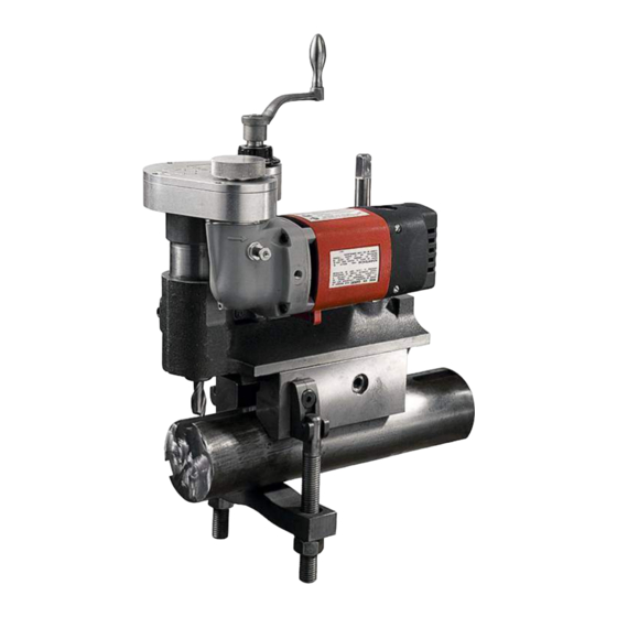
- Page 1 KM3000 KEY MILL MACHINE OPERATING MANUAL ORIGINAL INSTRUCTIONS P/N 16325 May 2019 Revision 10...
- Page 3 CLIMAX. CLIMAX hereby grants permission to download a single copy of this manual and of any revision hereto onto an electronic storage medium to be viewed and to print one copy of this manual or any revision hereto, pro-...
- Page 4 CLIMAX GLOBAL LOCATIONS Page B KM3000 Operating Manual...
- Page 5 CE DOCUMENTATION P/N 16325, Rev. 10 Page C...
- Page 6 CLIMAX will, at its option, either repair or replace the defective part and/ or correct any defect in the labor performed, both at no charge, and return the part or repaired machine shipping prepaid.
-
Page 7: Table Of Contents
TABLE OF CONTENTS HAPTER ECTION 1 INTRODUCTION ............1 . - Page 8 SDS ............89 Page 2 KM3000 Operating Manual...
- Page 9 A-2. KM3000 assembly with speed control parts list (P/N 85119)....... .
- Page 10 B-4. Controller schematic (P/N 36549) ........... . 87 Page 2 KM3000 Operating Manual...
- Page 11 1-3. KM3000 labels ........
- Page 12 This page intentionally left blank Page 2 KM3000 Operating Manual...
-
Page 13: Introduction
The appendices contain supplemental product information to aid in setup, operation, and maintenance tasks. Read this entire manual to familiarize yourself with the KM3000 before attempt- ing to set it up or operate it. AFETY ALERTS Pay careful attention to the safety alerts printed throughout this manual. -
Page 14: General Safety Precautions
ENERAL SAFETY PRECAUTIONS CLIMAX leads the way in promoting the safe use of portable machine tools and valve testers. Safety is a joint effort. You, the end user, must do your part by being aware of your work environment and closely following the operating procedures and safety precautions contained in this manual, as well as your employer’s safety... -
Page 15: Machine - Specific Safety Precautions
and interfaces that can cause severe impact, pinching, cutting, and other injuries. Except for stationary operating controls, avoid contact with mov- ing parts by hands or tools during machine operation. Remove gloves and secure hair, clothing, jewelry, and pocket items to prevent them from becoming entangled in moving parts. -
Page 16: Risk Assessment And Hazard Mitigation
Due to the unique nature of portable machining applications, identifying one or more hazards that must be addressed is typical. When performing the on-site risk assessment, it is important to consider the Porta- ble Machine Tool and the workpiece as a whole. Page 4 KM3000 Operating Manual... -
Page 17: Risk Assessment Checklist
ISK ASSESSMENT CHECKLIST The following checklist is not intended to be an all inclusive list of things to watch out for when setting up and operating this Portable Machine Tool. However, these checklists are typical of the types of risks the assembler and operator should con- sider. -
Page 18: Labels
ABELS The following warning and identification labels should be on your machine. If any are defaced or missing, contact CLIMAX immediately for replacements. 1-3. KM3000 ABLE LABELS P/N 59037 P/N 59044 Warning label: Warning label: wear ear pro- read the operating... -
Page 19: Overview
The auto- matically centering V-base is quick and easy to set up. The KM3000 clamps on any shaft up to 4.5" (114 mm) in diameter with the standard bar clamp. Cut stub- end keyways or mid-shaft keyways. - Page 20 Precision ACME thread leadscrew with roller thrust bearings • Sealed aluminum alloy gearbox permits operation at any angle • Precision ground quill housing assures smooth operation • The KM3000 key mill machine only needs 1.5" (38 mm) of shaft for clamping. Page 8 KM3000 Operating Manual...
-
Page 21: Controls
• Zeroing-type adjusting dial for controlling cutter depth The KM3000 key mill machine is designed to mount onto shafts from 1.5–4.5" (38–114 mm) in diameter. An optional chain clamp extends its application to fit onto shafts up to 10.5" (267 mm) in diameter. To fit shafts as small as 0.75" (19.1 mm) diameter, an optional shim kit is available. -
Page 22: Pneumatic Power
2.2.2 Hydraulic power Table 2-2 on page 11 lists operating specifications of the hydraulically powered version of the KM3000 using standard mineral-based hydraulic oil. CAUTION A hydraulically powered KM3000 operating with flame retardant, water/ glycol-based hydraulic fluid has operating specifications different from those listed below. - Page 23 CAUTION To avoid damaging the power unit pump, connect the hydraulic motor to the power unit before turning it on. The end mill turning direction on a hydraulically powered KM3000 depends on hydraulic line connections (see Figure 2-4). 2-4. HPU...
-
Page 24: Dimensions
IMENSIONS Figure 2-5 on page 13 show the machine and operating dimensions. Page 12 KM3000 Operating Manual... - Page 25 2-5. D IGURE IMENSIONS P/N 16325, Rev. 10 Page 13...
-
Page 26: Specifications
13 x 14 x 20 in. (33 x 36 x 51 cm) 1. See notice below. 2. See notice below. NOTICE If the front clamp is used on diameters smaller than 2.6" (66 mm), the machine will produce undesired work results. Page 14 KM3000 Operating Manual... - Page 27 CLIMAX electrical equipment is suitable for use in the physical environment and operating conditions specified below. When the physical environment or the oper- ating conditions are outside those specified, consult CLIMAX before putting the electrical equipment into service. 2-4. E...
- Page 28 This page intentionally left blank Page 16 KM3000 Operating Manual...
-
Page 29: Setup
- - - - - - - - - - - - - - - - - - - - - - - - - - - - - - - - - - - - - - -23 ERTICAL ADJUSTMENT This section describes the setup and assembly procedures for the KM3000 key mill machine. -
Page 30: Lifting And Rigging
IFTING AND RIGGING The KM3000 can be lifted from its crate by hand or using a strap fed underneath the gearbox between the quill and the vertical adjustment shaft, as shown in Figure 3-1 on page 18. 3-1. L IGURE... -
Page 31: Typical Shaft Mounting
2. Insert an end mill into the spindle with its flat aligned to the locking setscrew (see Figure 3-2). Degrease and thoroughly dry any collet used to hold small end mills. 3. While turning the vertical adjustment screw to raise or lower the quill housing, adjust the quill clamp to allow enough friction to hold the housing without preventing its travel. - Page 32 5. Start tightening at 20 ft-lbs (27.2 Nm) of torque. Torque the clamps evenly in 10 ft-lb (13.6 Nm) increments. CAUTION To avoid damaging the clamp bar do not tighten the clamps over 60 ft- lbs (81.6 Nm.) Page 20 KM3000 Operating Manual...
-
Page 33: Stub - End Mounting
END MOUNTING The mounting base of the key mill can extend beyond the end of a shaft provided the bar clamp is inboard not less than 1.5" (38 mm). See Figure 3-4 Do the following: 1. Set the key mill with the mounting base extending over the end of the shaft. -
Page 34: Small Shaft Mounting
A shim kit (P/N 11669) is available from your factory representative or by calling CLIMAX. ENCH VISE MOUNTING One available configuration is to clamp the key mill in a bench vise and use it as a stationary milling machine for small parts. -
Page 35: Vertical Adjustment
3.10 ERTICAL ADJUSTMENT The vertical adjustment screw sets the depth of the end mill. Turning clockwise moves the end mill down; counterclockwise moves it up. The dial is graduated in 0.001" (.025 mm) increments. CAUTION The key mill has a maximum vertical adjustment height of 1.75" (44 mm) from the bottommost position. - Page 36 This page intentionally left blank Page 24 KM3000 Operating Manual...
-
Page 37: Operation
OPERATION IN THIS CHAPTER: 4.1 P - - - - - - - - - - - - - - - - - - - - - - - - - - - - - - - - - - - - - - -25 OPERATION CHECKS 4.2 O - - - - - - - - - - - - - - - - - - - - - - - - - - - - - - - - - - - - - - - - -25... -
Page 38: Electric Machines
4. Connect the air supply line. 5. Press the emergency lever up until the word can be seen from the top OPEN of the valve. Check that the lever is pushed all the way. Page 26 KM3000 Operating Manual... -
Page 39: Hydraulic Machine
PECIAL REQUIREMENTS Machining out-of-the-ordinary keyways and other exceptional on-site milling jobs are well within the scope of the KM3000. With just a little creativity, the KM3000 works well on almost any operation calling for the milling of slots, flats, elongated holes, or other like features. -
Page 40: Extended Keyways
1. Secure the shaft so it will not rotate. 2. Referring to Figure 8 below, mount the key mill on top of the shaft, setting it level as described in Section 3.4 on page 19. Page 28 KM3000 Operating Manual... - Page 41 4-3. A IGURE XIALLY SPACED KEYWAYS 3. Cut the keyway as described in Section 4.2 on page 25. 4. Reposition the machine to the side of the shaft. Place a level on the side of the base to verify the machine is 90° to the first keyway. 5.
-
Page 42: Cross Milling
2. Set the key mill level on the shaft. 3. Secure the key mill to the shaft evenly by alternating tightening one 4-4. C IGURE ROSS MILLING bar clamp nut then the other. Page 30 KM3000 Operating Manual... -
Page 43: Maintenance
MAINTENANCE IN THIS CHAPTER: 5.1 M - - - - - - - - - - - - - - - - - - - - - - - - - - - - - - - - - - - - - -31 AINTENANCE CHECKLIST 5.2 A - - - - - - - - - - - - - - - - - - - - - - - - - - - - - - - - - - - - - - -32... -
Page 44: Approved Lubricants
Section 5.3.9 on Check periodically that air pressure is 80 psi (5.5 bar.) page 35 PPROVED LUBRICANTS CLIMAX recommends using the following lubricants at the locations indicated. Failure to use the appropriate lubricants can result in damage and premature machine wear. NOTICE Before servicing the machine with any of the lubricants in Table 5-2, consult the manufacturer’s MSDS. -
Page 45: Maintenance Tasks
5-2. A ABLE PPROVED LUBRICANTS Lubricant Brand Application Area Lubricant Jet Lube 550 Cutting bit set screw in quill Mobil VACTRA #2 Way oil Dovetail ways Heavy-Medium Way Oil Hydraulic system Hydraulic fluid Mobil DTE-24 Quill housing WARNING Disconnect the machine from power before servicing the machine. CAUTION Avoid damage to the machine and protect your warranty by using only approved lubricants. -
Page 46: Gearbox, Spindle, Quill Assembly
7. Put a coat of grease over gears and in all crevices. 5.3.7 Adjusting screw and cover Do the following to adjust the screw and cover: 1. Place the vertical adjusting lead screw into the gearbox. Page 34 KM3000 Operating Manual... -
Page 47: Electric Power Systems
2. Place the cover on the gearbox and screw down using six 8-32 x 5/8" screws. NOTICE Do not over-tighten the screws. 3. Push the dial knob onto the vertical lead screw, followed by the spring washer, thrust washer and then the snap ring. 4. -
Page 48: Hydraulic Power Systems
When new, change the filter after the first 72 hours of operation to remove any impurities in the system. From then on, replace the filter every 150–200 hours. Use a high-quality filter. CLIMAX recommends a 10-micron industrial-grade fil- ter. If the filtering system has a change-warning gauge, change the filter as often as the gauge indicates. -
Page 49: Storage And Shipping
STORAGE AND SHIPPING IN THIS CHAPTER: 6.1 S - - - - - - - - - - - - - - - - - - - - - - - - - - - - - - - - - - - - - - - - - - - - - -37 TORAGE 6.1.1 S - - - - - - - - - - - - - - - - - - - - - - - - - - - - - - - - - - - -37... -
Page 50: Shipping
To decommission the key mill machine prior to disposal, remove the drive assem- bly from the RDU and dispose of the drive assembly separately from the rest of the machine components. Refer to Appendix A for component assembly information. Page 38 KM3000 Operating Manual... -
Page 51: Appendix Aassembly Drawings
APPENDIX A ASSEMBLY DRAWINGS Drawing list A-1. KM3000 (P/N 85119) - - - - - - - - - - - - - - - - - - - - - - - 40 IGURE ASSEMBLY WITH SPEED CONTROL A-2. KM3000... -
Page 52: Igure A-1. Km3000 Assembly With Speed Control (P/N 85119)
AVAILABLE CONFIGURATIONS PART NO. DESCRIPTION 16001 MODEL KM3000 INCH 230V W/ SPEED CONTROL CE 16004 MODEL KM3000 METRIC 230V W/ SPEED CONTROL CE 36783 MODEL KM3000 METRIC 120V W/ SPEED CONTROL CE 37000 MODEL KM3000 INCH 120V W/ SPEED CONTROL DOM 39572 MODEL KM3000 METRIC 120V W/SPEED CONTROL DOM. -
Page 53: Igure A-2. Km3000 Assembly With Speed Control Parts List (P/N 85119)
ITEM P/N: DESCRIPTION 13737 (NOT SHOWN) KIT TOOL KM3000 KM4000 PM4000 16011 (NOT SHOWN) CRATE 9 X 24 X 11-7/8 KM3000 5/8 PLY HINGED 16022 SPINDLE & QUILL ASSY METRIC KM3000 16021 ASSY LEADSCREW VERT ADJ METRIC 3RD KM3000 30459... -
Page 54: Igure A-3. Km3000 Assembly With Speed Control Parts List (P/N 85119)
ITEM P/N: DESCRIPTION 13737 (NOT SHOWN) KIT TOOL KM3000 KM4000 PM4000 16011 (NOT SHOWN) CRATE 9 X 24 X 11-7/8 KM3000 5/8 PLY HINGED 16022 SPINDLE & QUILL ASSY METRIC KM3000 16021 ASSY LEADSCREW VERT ADJ METRIC 3RD KM3000 30459... -
Page 55: Igure A-4. Km3000 Assembly With Speed Control Parts List (P/N 85119)
ITEM P/N: DESCRIPTION 13737 (NOT SHOWN) KIT TOOL KM3000 KM4000 PM4000 16011 (NOT SHOWN) CRATE 9 X 24 X 11-7/8 KM3000 5/8 PLY HINGED 16022 SPINDLE & QUILL ASSY METRIC KM3000 16021 ASSY LEADSCREW VERT ADJ METRIC 3RD KM3000 30459... -
Page 56: Igure A-5. Km3000 Assembly (P/N 85122)
AVAILABLE CONFIGURATIONS PART NO. DESCRIPTION 16000 MODEL KM3000 INCH 120V DOMESTIC 16003 MODEL KM3000 METRIC 120V DOMESTIC 39571 MODEL KM3000 METRIC 230V 4TH A-5. KM3000 (P/N 85122) IGURE ASSEMBLY Page 44 KM3000 Operating Manual... -
Page 57: Igure A-6. Km3000 Assembly Parts List (P/N 85122)
ITEM P/N: DESCRIPTION 13737 (NOT SHOWN) KIT TOOL KM3000 KM4000 PM4000 16011 (NOT SHOWN) CRATE 9 X 24 X 11-7/8 KM3000 5/8 PLY HINGED 16022 SPINDLE & QUILL ASSY METRIC KM3000 16021 ASSY LEADSCREW VERT ADJ METRIC 3RD KM3000 30459... -
Page 58: Igure A-7. Km3000 Pneumatic Assembly (P/N 85123)
AVAILABLE CONFIGURATIONS PART NO. DESCRIPTION 16002 MODEL KM3000 INCH AIR 16005 MODEL KM3000 METRIC AIR A-7. KM3000 (P/N 85123) IGURE PNEUMATIC ASSEMBLY Page 46 KM3000 Operating Manual... -
Page 59: Igure A-8. Km3000 Pneumatic Assembly Parts List (P/N 85123)
PARTS LIST P/N 16002 ITEM P/N: DESCRIPTION 13737 (NOT SHOWN) KIT TOOL KM3000 KM4000 PM4000 15651 SPINDLE & QUILL ASSY INCH 3RD KM3000 15655 ASSY LEADSCREW VERT ADJ INCH 3RD KM3000 28839 BASE AND TOP SLIDE ASSY W/ BAR CLAMP... -
Page 60: Igure A-9. Km3000 Pneumatic Assembly (P/N 85124)
MODEL KM3000 INCH HYD 430 RPM @ 5 GPM W/O HPU 16009 MODEL KM3000 INCH HYD 664 RPM @ 5 GPM W/O HPU 16010 MODEL KM3000 METRIC HYD 430 RPM @ 5 GPM (HPU NOT INCLUDED) 45134 A-9. KM3000 (P/N 85124) -
Page 61: Igure A-10. Base And Top Slide Assembly (P/N 28839)
GIB .4915 X .1562 X 6.76 0-1 6 SS X 1.25 15647 CLAMP ASSY STANDARD KM3000 15656 ASSY TOP SLIDE INCH 2ND KM3000 16011 CRATE 9 X 24 X 11-7/8 KM3000 5/8 PLY HINGED (NOT SHOWN) 29152 PLATE MASS CE 38091 ASSY LEADSCREW TOP SLIDE KM3000 A-10. B... -
Page 62: Igure A-11. Base And Top Slide Assembly Metric (P/N 30459)
GIB .4915 X .1562 X 6.76 0-1 6 SS X 1.25 15647 CLAMP ASSY STANDARD KM3000 16025 ASSY TOP SLIDE METRIC 2ND KM3000 16325 MANUAL INSTRUCTION KM3000 KEY MILL 4TH GEN (NOT SHOWN) 29152 PLATE MASS CE 38091 ASSY LEADSCREW TOP SLIDE KM3000 A-11. B... -
Page 63: Igure A-12. Clamp Assembly (P/N 15647)
ITEM P/N: DESCRIPTION 10197 NUT 3/4-10 STDN ZINC PLATED 10198 WASHER THRUST .750 ID X 1.250 OD X .123 10422 ASSY CLAMP BOLT KM3000 15504 CASTING BLOCK CLAMP SMALL 15643 CLAMP BAR 15670 SCREW 1/2-13 X 1 LHSCS A-12. C... -
Page 64: Igure A-13. Top Slide Assembly (P/N 75077)
AVAILABLE CONFIGURATIONS PART NO DESCRIPTION 15656 ASSY TOP SLIDE INCH 2ND KM3000 16025 ASSY TOP SLIDE METRIC 2ND KM3000 PARTS LIST ITEM P/N: DESCRIPTION 11735 SCREW 5/16-18 X 1-1/4 SHCS 15507 SLIDE TOP INCH 2ND KM3000 16026 SLIDE TOP METRIC 2ND KM3000... -
Page 65: Igure A-14. Top Slide Leadscrew Assembly (P/N 38091)
WASHER THRUST .875 ID X 1.437 OD X .060 15999 PLUG HOLE 1-3/4 DIA MODIFIED 37981 NUT SELF LOCKING BRG ADJ SZ 4 38092 LEADSCREW TOPSLIDE KM3000 38116 COLLAR LEADSCREW BEARING A-14. T (P/N 38091) IGURE OP SLIDE LEADSCREW ASSEMBLY P/N 16325, Rev. -
Page 66: Igure A-15. Gearbox Spindle Drivetop Assembly (P/N 34403)
10167 SEAL 1.000 ID X 1.375 OD X .250 15517 GEAR SPUR 16DP 56T 20PA .43 X .97LG STEEL 34284 GEARBOX 4TH GENERATION KM3000 34285 GEARBOX COVER KM3000 79848 LABEL WARNING - CUTTING OF FINGERS OR HAND ROTATING BLADE GRAPHIC 1.13 TALL TRIANGLE YELLOW... -
Page 67: Igure A-16. Vertical Leadscrew Assembly (P/N 75096)
RING SNAP .672 OD X .035 THICK INVERTED 19492 LEADSCREW VERT ADJ INCH 3RD KM4000 CPM 4.67 INCH (19648) 15635 LEADSCREW VERT ADJ INCH 3RD KM3000 2.50 INCH (15655) 16020 LEADSCREW VERT ADJ METRIC 3RD KM3000 2.50 INCH (16021) 19634 LEADSCREW VERT ADJ METRIC 3RD KM4000 CPM 4.67 INCH (19649) -
Page 68: Igure A-17. Spindle And Quill Assembly (P/N 15651)
ITEM P/N: DESCRIPTION 10150 BRG BALL .7874 ID X 1.8504 OD X .5512 15514 ASSY QUILL 2ND KM3000 1.75 TRAVEL 15518 SPINDLE INCH 5/8 3RD KM3000 15669 SEAL 1.500 ID X 1.874 OD X .250 37405 SCREW 1/2-20 X .425 END MILL SET SCREW A-17. -
Page 69: Igure A-18. Spindle And Quill Assembly Metric (P/N 16022)
PARTS LIST ITEM P/N: DESCRIPTION 10150 BRG BALL .7874 X 1.8504 X .5512 2/SHLDS 15514 ASSY QUILL 2ND KM3000 1.75 TRAVEL 15669 SEAL 1.500 ID X 1.874 OD X .250 16023 ASSY SPINDLE 16MM METRIC 3RD KM3000 A-18. S (P/N 16022) -
Page 70: Igure A-19. Motor Electric Assembly (P/N 81474)
59044 LABEL WARNING - CONSULT OPERATOR'S MANUAL 78741 LABEL WARNING CRUSH FOOT 78748 LABEL WARNING FLYING DEBRIS/LOUD NOISE 78824 LABEL WARNING - DO NOT EXPOSE TO WATER A-19. M (P/N 81474) IGURE OTOR ELECTRIC ASSEMBLY Page 58 KM3000 Operating Manual... -
Page 71: Igure A-20. Motor Assembly (P/N 11895)
A-20. M (P/N 11895) IGURE OTOR ASSEMBLY P/N 16325, Rev. 10 Page 59... -
Page 72: Igure A-21. Motor Assembly Parts List (P/N 11895)
A-21. M (P/N 11895) IGURE OTOR ASSEMBLY PARTS LIST Page 60 KM3000 Operating Manual... -
Page 73: Igure A-22. Cap Motor End Assembly (P/N 81475)
AVAILABLE CONFIGURATIONS DESCRIPTION 34142 CAP MOTOR END ASSY W/2-POLE CONNECTOR 120V 35973 CAP MOTOR END ASSY W/3-POLE CONNECTOR 230V PARTS LIST ITEM PART No. DESCRIPTION 10313 CONNECTOR PLUG MALE SNAP BULLET 16-14 GA (KB) (NOT SHOWN) 12574 CONDUIT NUT 1/2 NPT 15022 CONNECTOR PLUG FEMALE SNAP BULLET 16-14 GA .180 DIA (KB) (NOT SHOWN) -
Page 74: Igure A-23. Mtr/Spd Controller Assembly (P/N 36686)
36684 MOTOR ASSY ELECTRIC 230V 59044 LABEL WARNING - CONSULT OPERATOR'S MANUAL 78824 LABEL WARNING - DO NOT EXPOSE TO WATER 79218 CONTROLLER BB3000 230V 50/60 HZ CE A-23. MTR/SPD (P/N 36686) IGURE CONTROLLER ASSEMBLY Page 62 KM3000 Operating Manual... -
Page 75: Igure A-24. Electric Motor Assemblies 120V (P/N 36780) And 230V (P/N 36684)
PARTS LIST ITEM PART No. DESCRIPTION 10168 KNOB ADJUSTMENT 2 INCH KNURLED 17131 SCREW 1/4-20 X 7/8 SHCS 34142 CAP MOTOR END ASSY W/ 2-POLE CONNECTOR 120V (36780) 35973 CAP MOTOR END ASSY W/ 3-POLE CONNECTOR 230V (36684) 34653 GEAR SPUR 16DP 26T 20PA .437 X .78LG STEEL 34662 MOTOR ELEC 120V 4TH MODIFIED (36780) 36688... -
Page 76: Igure A-25. 230V 50/60 Hce Controller (P/N 79218)
TO LID SEE DETAIL A A-25. 230V 50/60 H (P/N 79218) IGURE CONTROLLER Page 64 KM3000 Operating Manual... -
Page 77: Igure A-26. Multiple Model Controller (P/N 79218)
TO ENCLOSURE A-26. M (P/N 79218) IGURE ULTIPLE MODEL CONTROLLER P/N 16325, Rev. 10 Page 65... -
Page 78: Ontroller Parts List
GROUND BUSS 7 POLE COPPER CE CERTIFIED 82961 ENCLOSURE 230V BB3000 PL2000 CONTROLLER CE 38324 (NOT SHOWN) TERMINAL SPADE FEMALE 90 DEG 12-10 82984 LEGEND PLATE BB3000 120/230V SPEED CONTROLLER A-27. C (P/N 79218) IGURE ONTROLLER PARTS LIST Page 66 KM3000 Operating Manual... -
Page 79: Igure A-28. Iline Switch (P/N 37938)
A-28. I (P/N 37938) IGURE LINE SWITCH P/N 16325, Rev. 10 Page 67... -
Page 80: Neumatic Drive Assembly
ITEM P/N: DESCRIPTION 10168 KNOB ADJUSTMENT 2 INCH KNURLED 10326 GEAR SPUR 26T 16DP 1.625PD 10380 VALVE & HOSE ASSY AIR KM3000 KM4000 PM4000 38708 MOTOR AIR ASSY KM3000 A-29. P (P/N 38716) IGURE NEUMATIC DRIVE ASSEMBLY Page 68 KM3000 Operating Manual... -
Page 81: Igure A-30. Valve And Hose Air Assembly (P/N 10380)
PARTS LIST ITEM P/N: DESCRIPTION 13208 FTG QD COUPLER 1/2B 1/2 NPTF PNEUMATIC 13209 FTG QD NIPPLE 1/2B 1/2 NPTM PNEUMATIC 15915 HOSE ASSY 801 1/2 X 1/2 NPTMS X 1/2 NPTMS X 72 22229 VALVE NEEDLE 1/2 IN. 33809 FTG NIPPLE 1/2 NPT CLOSE BRASS 34734 LABEL WARNING 3-1/2 X 11... -
Page 82: Igure A-31. Pneumatic Conditioning Unit Assembly (P/N 78264)
ASSEMBLED SCALE 1 : 5 A-31. P (P/N 78264) IGURE NEUMATIC CONDITIONING UNIT ASSEMBLY Page 70 KM3000 Operating Manual... -
Page 83: Igure A-32. Pneumatic Conditioning Unit Assembly Parts List (P/N 78264)
PARTS LIST ITEM P/N: DESCRIPTION 10160 SCREW 1/4-20 X 3/4 SHCS 11365 SCREW 1/4-20 X 3/4 BHSCS 12616 FTG PLUG 1/8 NPTM SOCKET 13489 WASHER 5/16 FLTW SAE 14726 SCREW 10-32 X 1/4 SHCS 19729 NUT 5/16-18 NYLON INSERT LOCKNUT 22235 FTG BARB #10-32 X 1/8 HOSE 27895... -
Page 84: Igure A-33. Pneumatic Motor Assembly (P/N 38708)
A-33. P (P/N 38708) IGURE NEUMATIC MOTOR ASSEMBLY Page 72 KM3000 Operating Manual... -
Page 85: Igure A-34. Pneumatic Motor Assembly Parts List (P/N 38708)
38710 RING SNAP 1.850 OD SPIRAL MEDIUM DUTY 38711 RING SNAP 25/32 OD X .031 TH SPIRAL MEDIUM DUTY 38715 MOTOR MODIFIED AIR KM3000 KM4000 520 RPM 59044 LABEL WARNING - CONSULT OPERATOR'S MANUAL 78741 LABEL WARNING CRUSH FOOT 78748 LABEL WARNING FLYING DEBRIS/LOUD NOISE A-34. -
Page 86: Igure A-35. Hydraulic Key Mill Gearbox (P/N 34935)
SEAL 1.000 ID X 1.375 OD X .250 12418 SCREW 1/4-20 X 5/8 SHCS 15517 GEAR SPUR 16DP 56T 20PA .43 X .97LG STEEL 34284 GEARBOX 4TH GENERATION KM3000 34285 GEARBOX COVER KM3000 75048 PLATE SERIAL YEAR MODEL CE 2.0 X 2.63 79848 LABEL WARNING - CUTTING OF FINGERS OR HAND ROTATING BLADE GRAPHIC 1.13 TALL TRIANGLE... -
Page 87: Igure A-36. Box Gear Assembly (P/N 21022)
SCREW 8-32 X 5/8 SHCS 10167 SEAL 1.000 ID X 1.375 OD X .250 15517 GEAR SPUR 16DP 56T 20PA .43 X .97LG STEEL 34284 GEARBOX 4TH GENERATION KM3000 34285 GEARBOX COVER KM3000 75048 PLATE SERIAL YEAR MODEL CE 2.0 X 2.63 79328 LABEL WARNING - CONSULT OPERATOR'S MANUAL GRAPHIC .75 DIA... -
Page 88: Igure A-37. Hydraulic Motor Assembly (P/N 35002)
LABEL WARNING - CUTTING OF FINGERS OR HAND ROTATING BLADE GRAPHIC 1.13 TALL TRIANGLE YELLOW 80041 ASSY HOSE 3/8 X 1/2 QD MALE X #6 JICF X 24 CE A-37. H (P/N 35002) IGURE YDRAULIC MOTOR ASSEMBLY Page 76 KM3000 Operating Manual... -
Page 89: Igure A-38. 250-450 Rpm Hydraulic Motor Assembly (P/N 41432)
PARTS LIST ITEM P/N: DESCRIPTION 12647 SCREW 1/4-28 X .75 SHCS 12849 FTG ELBOW SAE-6 MALE X #6 JIC MALE 90 DEG 12853 SCREW 1/4-28 X 5/8 FHSCS 20379 GEAR SPUR MOTOR 16DP 1.625PD SPECIAL HYD MOTOR 21025 MOTOR HYD 1.21 CU IN. CHAR-LYNN 35003 FLANGE MOTOR MTG HYD 4TH GEN GEARBOX 56793... -
Page 90: Igure A-39. Chain Clamp Assembly (P/N 10378)
15505 BASE REF. PARTS LIST ITEM P/N: DESCRIPTION 27364 CHAIN CLAMP ASSY 10-1/2 DIA KM3000 2ND A-39. C (P/N 10378) IGURE HAIN CLAMP ASSEMBLY Page 78 KM3000 Operating Manual... -
Page 91: Igure A-40. Chain Clamp Assembly Diameter (P/N 27364)
PARTS LIST ITEM P/N: DESCRIPTION 15504 CASTING BLOCK CLAMP SMALL 15835 CASTING -BLOCK CLAMP 10206 ROCKER CHAIN CLAMP 27385 BOLT - CHAIN CLAMP 10197 NUT 3/4-10 STDN ZINC PLATED 27366 CHAIN WRENCH 3/4 PITCH .240 DIA PIN (VMI) 10198 WASHER THRUST .750 ID X 1.250 OD X .123 15670 SCREW 1/2-13 X 1 LHSCS A-40. -
Page 92: Ross Milling Adapter
10454 BASE REF. PARTS LIST ITEM P/N: DESCRIPTION 10255 CROSS MILLING ADAPTER 19950 SCREW 1/2-13 X 3 1/4 SHCS A-41. C (KM4000 ) (P/N 10381) IGURE ROSS MILLING ADAPTER BASE SHOWN Page 80 KM3000 Operating Manual... -
Page 93: Igure A-42. Shim Kit Assembly (P/N 11669)
REF. ONLY PARTS LIST ITEM P/N: DESCRIPTION 10160 SCREW 1/4-20 X 3/4 SHCS 11668 SHIM SET SMALL DIA MILLING KM3000 (KB) 19605 (NOT SHOWN) DRAWING INSTRUCTIONS SHIM INSTALLATION KM3000 A-42. S (P/N 11669) IGURE HIM KIT ASSEMBLY P/N 16325, Rev. 10... -
Page 94: Able A-1. Service Parts List
The following critical parts may occasionally need to be replaced due to loss, wear, or damage, and are available for purchase from CLIMAX.. A-1. S ABLE ERVICE PARTS LIST Part Description Quantity number 10189 SCREW 1/4-20 X 5/8 SSSHDPPL 10190... - Page 95 ABLE ERVICE PARTS LIST Part Description Quantity number 31769 SP BRUSH CARBON KM3000/87 MOTOR 230V 37405 SCREW MODIFIED 1/2-20 X .425 END MILL SCREW 37981 NUT SELF LOCKING BRG ADJ SZ 4 (VMI) 38091 ASSY LEADSCREW TOP SLIDE KM3000 38116...
- Page 96 This page intentionally left blank Page 84 KM3000 Operating Manual...
-
Page 97: Appendix Bschematics
APPENDIX B SCHEMATICS Schematic list B-1. P (P/N 59246) - - - - - - - - - - - - - - - - - - - - - - - - - - - - - - - - 85 IGURE NEUMATIC SCHEMATIC B-2. - Page 98 B-3. E IGURE LECTRICAL SCHEMATIC Page 86 KM3000 Operating Manual...
- Page 99 Portable Machine Tools, Inc. 2712 E. SECOND ST. NEWBERG, OR. 97132 USA 800-333-8311 OR 503-538-2185 WWW.CPMT.COM CLIMAX SERIAL NO. YEAR MODEL SUPPLY VOLTS / PHASE / Hz LARGEST LOAD INTERRUPT kA B-3. C (P/N 36549) IGURE ONTROLLER SCHEMATIC P/N 16325, Rev. 10...
- Page 100 This page intentionally left blank Page 88 KM3000 Operating Manual...
-
Page 101: Appendix Csds
APPENDIX C Contact CLIMAX for the current Safety Data Sheets. P/N 16325, Rev. 10 Page 89... - Page 102 This page intentionally left blank Page 90 KM3000 Operating Manual...
Need help?
Do you have a question about the KM3000 and is the answer not in the manual?
Questions and answers