
Subscribe to Our Youtube Channel
Related Manuals for Climax BB6100


Summary of Contents for Climax BB6100
- Page 1 BB6100 BORING BAR OPERATING MANUAL ORIGINAL INSTRUCTIONS PN: 57017 May 2019 Revision 3...
- Page 3 CLIMAX. CLIMAX hereby grants permission to download a single copy of this manual and of any revision hereto onto an electronic storage medium to be viewed and to print one copy of this...
- Page 4 CLIMAX WORLDWIDE LOCATIONS Page B BB6100 Operating Manual...
-
Page 5: Table Of Contents
TABLE OF CONTENTS INTRODUCTION ........................1 Limited Warranty ............................1 Alerts ................................. 2 Safety Precautions ............................. 2 Machine Specific Safety Practices ......................3 Risk Assessment and Hazard Mitigation ....................5 Risk Assessment Checklist ........................6 OVERVIEW ..........................7 About this manual ............................8 2.1.1 Recommended tools .......................... - Page 6 Tool carrier maintenance ........................50 Hydraulic power unit and motor ........................ 50 STORAGE ..........................51 Tool kit ..............................51 Spare Parts ..............................53 EXPLODED VIEWS AND PARTS LISTS ................55 SCHEMATICS ........................91 SDS ............................95 Page ii BB6100 Operating Manual...
-
Page 7: Introduction
CLIMAX. About This Manual CLIMAX provides the contents of this manual in good faith as a guideline to the operator. CLIMAX cannot guarantee that the information contained in this manual is correct for applications other than the application described in this manual. Product specifications are subject to change without notice. -
Page 8: Alerts
Safety Precautions CLIMAX leads the way in promoting the safe use of portable machine tools. Safety is a joint effort. You, the machine operator, must do your part by being aware of your work environment and closely following the operating procedures and safety precautions contained in this manual, as well as your employer’s safety guidelines. -
Page 9: Machine Specific Safety Practices
Work Area – Keep the work area around the machine clear of clutter. Keep all cords and hoses away from the work area when operating the machine. Lifting – Many CLIMAX machine components are very heavy. Whenever possible, lift the machine or its components using proper hoisting equipment and rigging. - Page 10 To reduce the likelihood of these disorders, follow these guidelines: Use minimum hand grip force Keep wrists straight Avoid exposure to continue vibration Avoid repeated bending of wrists and hands Keep hands and arms warm and dry Page 4 BB6100 Operating Manual...
-
Page 11: Risk Assessment And Hazard Mitigation
Risk Assessment and Hazard Mitigation Machine Tools are specifically designed to perform precise material-removal operations. Stationary Machine Tools include lathes and milling machines and are typically found in a machine shop. They are mounted in a fixed location during operation and are considered a complete, self-contained machine. -
Page 12: Risk Assessment Checklist
I checked that all affected personnel understand the danger zone and are clear of it. I evaluated and mitigated any other potential risks specific to my work area. Page 6 BB6100 Operating Manual... -
Page 13: Overview
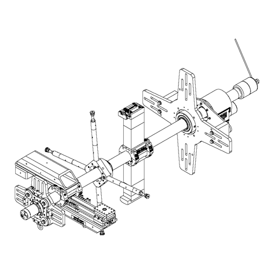
OVERVIEW Machining range from 8.8–38" (224–965 mm) diameter and faces from 7.5–42.1" (191–1,069 mm) are quickly restored to original condition with the CLIMAX BB6100 Portable Boring Machine. This modular machine tool shown in Figure 2-1 is dedicated to on-site restoration of worn internal diameters to precise roundness and dimensional accuracy ready to accept new bearings, sleeves, shafts, or similar mating parts. -
Page 14: About This Manual
About this manual This manual describes the most effective setup and operation of your Model BB6100 Portable Boring Machine. All parts meet CLIMAX’s strict quality standards. For maximum safety and performance, read the entire manual before operating this machine. 2.1.1 Recommended tools CLIMAX includes a general tool kit with the machine. -
Page 15: Specifications And Dimensions
Specifications and Dimensions P/N: 57017, Rev. 3 Page 9... - Page 16 Page 10 BB6100 Operating Manual...
- Page 17 P/N: 57017, Rev. 3 Page 11...
- Page 18 Page 12 BB6100 Operating Manual...
- Page 19 P/N: 57017, Rev. 3 Page 13...
-
Page 20: Axial Feed Assembly
Axial Feed Assembly Page 14 BB6100 Operating Manual... -
Page 21: Setup
SETUP Before proceeding with set-up of the BB6100, determine the best placement of each module on the bar. The RDU and tool head assemblies can be located anywhere along the bar. Make sure to allow space for them while planning your set-up. -
Page 22: Installing End-Mount Bearing Support
2. Inspect the bar for nicks or cuts. Dress the bar smooth with a honing stone if necessary. Clean the bar with solvent to remove dirt and chips. A bar with nicks or gouges can severely damage mating parts, including the tool carrier and RDU. Page 16 BB6100 Operating Manual... - Page 23 3. Slide the boring bar into the workpiece. 4. Slide the bearing supports onto the ends of the bar. 5. Using a hoist, hold the bar and bearings in the approximate center of the bore. Alignment within 1/8" (3 mm) is sufficient. 1/8”...
- Page 24 13. For mounting another end-mount bearing support, repeat steps #8 through #10. If using an ID-mount bearing assembly, see Section 3.4 on page 19. CLIMAX recommends no fewer than two support assemblies to obtain adequate machine stability. The maximum recommended unsupported bar length is 5 feet (1.5 m).
-
Page 25: Id-Mount Bearing Support
3.3.2 Clamping the bearing assembly to the bar Do the following to clamp the bearing assembly to the bar: 1. Remove the screws holding the lock plate. 2. Slide the lock plate away from the lock nut. 3. Rotate the lock nut using both hands until it is snug. This is the zero reference point. - Page 26 Chuck body 2. ID- IGURE MOUNT BEARING COMPONENT Modified bearing Short jacking bolt Long jacking bolt 3.5" (90 mm) jaw 5.5" (140 mm) jaw 7.5" (190 mm) jaw 9.5" (240 mm) jaw 1" (25 mm) spacer Page 20 BB6100 Operating Manual...
- Page 27 If using the small plate chuck, do the following before moving on to step 5: a. Screw short or long jacking bolts into the sides of the plate chuck. 3. S IGURE MALL PLATE CHUCK LEFT AND JACKING SCREW RIGHT b.
- Page 28 Mount the bearing to the chuck body using spring washers, flat washers, and screws. 5. Slide one bearing support assembly onto the boring bar. 6. Position the bearing in the bore. 7. Use a dial indicator to precisely align the boring bar to the bearing. Page 22 BB6100 Operating Manual...
-
Page 29: If Mounting An End-Mount Bearing
8. Center the bar by evenly adjusting the jacking screws then tighten the hex-head cap screws. 9. Slide the bar and bearing support into the work piece. 10. Using a dial indicator and the jacking screws, center the bar inside the work piece. -
Page 30: Rdu Setup
The RDU can be placed anywhere along the boring bar. CAUTION The boring bar is not hardened. To prevent damage to the bar, do not strike it against the bearing supports or the work piece. Page 24 BB6100 Operating Manual... - Page 31 When mounting the RDU, the slot in the drive hub must align with the lead screw slot in the bar. 6. A IGURE LIGN THE DRIVE HUB SLOT WITH THE LEAD SCREW 1. Inside the torque arms are mounted to (radial direction is optional) RDU housing. 2.
-
Page 32: Mounting The Mechanical Axial Feed Unit
4. Secure the stop rod to a stationary object to engage the feed mechanism. If the axial feed unit is moved to the opposite end of the bar, the feed direction will be reversed. Check the feed direction before operating the machine. Page 26 BB6100 Operating Manual... -
Page 33: Setting Feed Direction And Rate
WARNING A loose trip rod can cause damage and injury. Secure the trip rod to a fixed object. 3.7.1 Setting feed direction and rate Feed direction and feed rate are set using the feed adjustment knob. Axial feed rate is variable from 0.003–0.020"... -
Page 34: Feed Toward The Axial Feed Unit
To reduce the rate of feed, pull the plunger and lock in the out position then turn the adjustment knob clockwise. To increase the feed rate, pull the plunger and lock in position then turn the adjustment knob counterclockwise. The feed is adjustable while the machine is running. Page 28 BB6100 Operating Manual... -
Page 35: Stopping The Feed
8. M IGURE INIMUM FEED LEFT AND MAXIMUM FEED RIGHT 3.7.7 Stopping the feed To quickly stop the boring head from feeding, pull the stop rod out of the torque hub on the axial feed unit. This is helpful when cutting up to a shoulder. Mounting the Electric Axial Feed Assembly The electric feed unit consists of the adaptor plate, manual override, electric motor assembly, and remote pendant control. - Page 36 Mechanical override assembly Adapter plate Bar end cap NOTICE If the axial feed unit is moved to the opposite end of the bar, the feed direction will reverse. Check feed direction before operating the machine. Page 30 BB6100 Operating Manual...
-
Page 37: Tool Head Setup
3.8.1 Setting the Axial Feed Rate The feed potentiometer controls the axial feed rate. Turning the knob counterclockwise decreases the feed rate; turning the knob clockwise increases the feed rate. Axial feed rate is adjustable and variable from 0.010–0.500" (0.25–13 mm) per minute. -
Page 38: Small Bore Tool Carrier Boring Head Setup
Leading tool holder Trailing tool holder 2" (50.18 mm) spacer with slot 2" (50.18 mm) spacer no slot 6" (152.4 mm) spacer with slot 6" (152.4 mm) spacer no slot 10-13 Socket head cap screws (different sizes) Page 32 BB6100 Operating Manual... -
Page 39: Micro-Adjust Boring Head
Each division in the dial screw resolves in 0.001" (0.025 mm) change in diameter. The dove tail adjustment set screws are set to the correct load by CLIMAX and should not be necessary to re-adjust them. These set screws have Vibratite-VC3 in order to avoid losing tension during vibration. - Page 40 BB6100 Micro adjust boring head tool range table 8.8–40.8" (224–1,036 mm) diameter Bore range diameter Number of spacer blocks required 2" (51 mm) 4" (102 mm) 8" (203 mm) block block block 8.8–12.8" (224–325 mm) 12.8–16.8" (325–427 mm) 16.8–20.8" (427–528 mm) 20.8–24.8"...
- Page 41 BB6100 Solid tooling boring head tool range table 9.7–42.2" (246–1,072 mm) diameter Number of spacer blocks required Bore range diameter 0.75" (19 2" (51 mm) 4" (102 8" (203 mm) mm) block block mm) block block 9.7–12.7" (246–323 mm) 11.2–14.2" (285–361 mm) 13.7–16.7"...
-
Page 42: Boring Head Setup
3. Mount the boring head and the counterweight on the stack up blocks. Number Component Stack-up blocks Boring head Tool carrier Counterweight Page 36 BB6100 Operating Manual... - Page 43 P/N: 57017, Rev. 3 Page 37...
-
Page 44: To Lock The Tool Carrier On The Bar For Other Operations
2. Remove the screws on each end of the brass nut. (If there is too much play in the brass nut, the center set screw can be tightened.) 10. R IGURE EMOVING THE BRASS NUT Page 38 BB6100 Operating Manual... -
Page 45: Install The Slide Arm Onto The Tool Carrier
3. Using the previous boring head tool range table, select the required spacers and screws. Clamp all parts tightly to the tool carrier. 4. Grind a 1/2" square HSS tool bit (see following illustration) or install inserted carbide tool holder with insert. Geometry shown is for a left-hand tool. -
Page 46: Adjusting The Tool Carrier For Perpendicularity
Range Table and Mechanical Facing Head exploded view drawing to see how the parts fit together). 2. Mount the facing head onto the tool carrier. 3. Secure a sharpened tool bit in the tool carrier. Page 40 BB6100 Operating Manual... - Page 47 CAUTION The facing head is operational in only one direction. Check that the bar rotates in the correct direction the tool bit faces appropriately. Number Component Feed trip Facing head Set screws Tool bit Cutting depth setting screw Rotation Tool carrier Boring bar 4.
- Page 48 The counterweight mounts on the side of the tool carrier opposite of the facing head. The components figure shows spacers for one side only. Use an identical spacer stack for each side. The facing head can bore diameters as small as 23.25" (590.55 mm). Page 42 BB6100 Operating Manual...
-
Page 49: Hydraulic Power Preparation And Connection
3.17 Hydraulic power preparation and connection CAUTION Connect the hydraulic motor to the power unit pump prior to turning on the power unit. Failure to do so will damage the pump and void all warranties. The hydraulic motor mounts to the rotational drive unit. Hydraulic hoses with quick disconnect fittings connect to hydraulic power unit and the hydraulic motor. - Page 50 This page is intentionally left blank Page 44 BB6100 Operating Manual...
-
Page 51: Operation
OPERATION Using the remote pendants Operator controls for the machine are located on the remote pendants, described below. CAUTION The bar rotation and the axial feed are independent of each other. Be sure the feed is OFF when the bar is not running. 4.1.1 Feed pendant The following is a description of the feed pendant controls:... -
Page 52: Hpu Pendant
With a socket on the hexagon shaft, run with an electric drill or speed wrench. To re-engage the feed, remove the socket, turn the feed on slow, and shift the feed lever to the forward position. Page 46 BB6100 Operating Manual... -
Page 53: Pre-Startup Checks
Pre-startup checks Do the following before operating the boring bar: 1. Tie down the RDU torque arms and the axial feed unit stop rod. 2. Use only properly sharpened tool bits. 3. Secure all machine parts, including the bearing assemblies, the tool carrier, and the boring head. -
Page 54: Disassembly
10. Place a wooden support in the bottom of the bore to support the bar. 11. Remove the bearing supports from the work piece. 12. Slide the bar out of the bore using the wooden support. Page 48 BB6100 Operating Manual... -
Page 55: Maintenance
MAINTENANCE Recommended lubricants Lubricant Brand Where used Gear grease Polytac EP #2 Rotational drive, axial feed units Light Oil LPS 2 Unpainted surfaces Cutting oil UNOCAL KOOLKUT Tool bits, work pieces Hydraulic oil Union UNAX AW32 Hydraulic motor Anti-wear hydraulic oil Anti-seize lubricant Moly Grade Anti-seize Jacking bolts... -
Page 56: Mechanical Facing Head Assembly
Before operating the boring bar, pump light oil into the oiler in the side of the carrier. Be careful not to damage the scrapers. Before storage, lightly oil all parts to prevent rusting. Hydraulic power unit and motor See the HPU manufacturer’s documentation for information about your HPU and its maintenance. Page 50 BB6100 Operating Manual... -
Page 57: Storage
To prevent rusting, spray with a moisture-displacement material such as JET-LUBE 550 for short-term storage, LPS 3 for long-term storage. Store the machine in the container provided. Place desiccant bags or vapor wrap around the machine to absorb moisture. Tool kit 4 . BB6100 (P/N 54262) ABLE TOOL KIT DESCRIPTION... - Page 58 54411 STANDOFF RDU 6IN Piece 54412 STANDOFF RDU 6.5IN Piece 54717 TOOL BEARING BB6100 Piece WRENCH SPANNER FOR 3.5 DIA DODGE IMPERIAL BRG 56734 Piece OFFSET 1 IN 57017 MANUAL INSTRUCTION BB6100 BORING BAR Piece Page 52 BB6100 Operating Manual...
-
Page 59: Spare Parts
SPACER BOLT EYE 1/2 THK 22409 DIAL FEED Mechanical axial feed assembly 14303 ROD STOP 54217 SHOE ADJUSTABLE TOOL CARRIER BB6100 SET NUT AXIAL LEAD SCREW 3/4-5 ACME Net fit tool carrier 54221 BB6100 14771 SCREW 5/16-18 X 3/4 BHSCS 22205... - Page 60 RIGHT HAND HOLDER INSERT 3/4 SQ SHANK NEG RAKE 33997 LEFT HAND INSERT CARBIDE 80 DEG 1/2 IC 1/64 NOSE 41407 RADIUS KC5010 INSERT CARBIDE 80 DEG 3/8 IC 1/64 NOSE 50741 RADIUS CPGM-3251 KC5010 Page 54 BB6100 Operating Manual...
-
Page 61: Exploded Views And Parts Lists
The following diagrams and parts are for your reference purposes only. The machine Limited Warranty is void if the machine has been tampered with by anyone who has not been authorized in writing by CLIMAX to perform service on the machine. P/N 57017, Rev. 3... - Page 62 11. 4- 3.5 ID (P/N 92850) IGURE JAW CHUCK FACE ADJUSTING BEARING ASSEMBLY Page 56 BB6100 Operating Manual...
- Page 63 12. 4- 3.5 ID (P/N 92850) IGURE JAW CHUCK FACE ADJUSTING BEARING ASSEMBLY PARTS LIST P/N 57017, Rev. 3 Page 57...
- Page 64 13. ID- (P/N 54355) IGURE MOUNT BEARING ASSEMBLY Page 58 BB6100 Operating Manual...
- Page 65 14. S (P/N 53710) IGURE PIDER BEARING ASSEMBLY END SUPPORT P/N 57017, Rev. 3 Page 59...
- Page 66 15. S (P/N 53840) IGURE PIDER BEARING THREE ARM END SUPPORT ASSEMBLY Page 60 BB6100 Operating Manual...
- Page 67 16. 4- (P/N 22091) IGURE ARM END MOUNT BEARING ASSEMBLY P/N 57017, Rev. 3 Page 61...
- Page 68 17. B (P/N 71618) IGURE ORING BAR CHART ASSEMBLY Page 62 BB6100 Operating Manual...
- Page 69 18. B (P/N 71618) IGURE ORING BAR CHART ASSEMBLY PARTS LIST P/N 57017, Rev. 3 Page 63...
- Page 70 19. M (P/N 23299) IGURE ECHANICAL AXIAL FEED UNIT ASSEMBLY Page 64 BB6100 Operating Manual...
- Page 71 20. M (P/N 23299) IGURE ECHANICAL AXIAL FEED UNIT ASSEMBLY PARTS LIST P/N 57017, Rev. 3 Page 65...
- Page 72 21. E (P/N 41062) IGURE LECTRIC AXIAL FEED ASSEMBLY Page 66 BB6100 Operating Manual...
- Page 73 22. E (P/N 41062) IGURE LECTRIC AXIAL FEED ASSEMBLY PARTS LIST P/N 57017, Rev. 3 Page 67...
- Page 74 23. E (P/N 86681) IGURE LECTRIC AXIAL FEED ASSEMBLY Page 68 BB6100 Operating Manual...
- Page 75 24. M (P/N 41064) IGURE ECHANICAL FEED ASSEMBLY FOR ELECTRIC AXIAL FEED P/N 57017, Rev. 3 Page 69...
- Page 76 25. M (P/N 41064) IGURE ECHANICAL FEED ASSEMBLY PARTS LIST FOR ELECTRIC AXIAL FEED Page 70 BB6100 Operating Manual...
- Page 77 26. R (P/N 22221) IGURE OTATIONAL DRIVE ASSEMBLY P/N 57017, Rev. 3 Page 71...
- Page 78 27. R (P/N 22221) IGURE OTATIONAL DRIVE ASSEMBLY PARTS LIST Page 72 BB6100 Operating Manual...
- Page 79 28. F (P/N 75682) IGURE ACING HEAD CHART ASSEMBLY P/N 57017, Rev. 3 Page 73...
- Page 80 29. F (P/N 75682) IGURE ACING HEAD CHART ASSEMBLY PARTS LIST Page 74 BB6100 Operating Manual...
- Page 81 30. B (P/N 81561) IGURE ORING FACING SLIDE ARM SET ASSEMBLY P/N 57017, Rev. 3 Page 75...
- Page 82 31. B (P/N 81561) IGURE ORING FACING SLIDE ARM SET ASSEMBLY PARTS LIST Page 76 BB6100 Operating Manual...
- Page 83 32. B (P/N 86638) IGURE ORING FACING TOOL ARM CHART ASSEMBLY P/N 57017, Rev. 3 Page 77...
- Page 84 33. B (P/N 86638) IGURE ORING FACING TOOL ARM CHART ASSEMBLY PARTS LIST Page 78 BB6100 Operating Manual...
- Page 85 34. T (P/N 54224) IGURE OOL CARRIER ASSEMBLY P/N 57017, Rev. 3 Page 79...
- Page 86 35. A (P/N 54223) IGURE DJUSTABLE AXIAL NUT LEAD SCREW ASSEMBLY Page 80 BB6100 Operating Manual...
- Page 87 36. B (P/N 81246) IGURE ORING HEAD SOLID TOOLING P/N 57017, Rev. 3 Page 81...
- Page 88 37. B (P/N 60382) IGURE ORING HEAD SET SUPPLEMENTAL SOLID TOOLING HOLDERS Page 82 BB6100 Operating Manual...
- Page 89 38. M (P/N 79325) IGURE ICRO ADJUST BORING HEAD ASSEMBLY P/N 57017, Rev. 3 Page 83...
- Page 90 39. M (P/N 79325) IGURE ICRO ADJUST BORING HEAD ASSEMBLY PARTS LIST Page 84 BB6100 Operating Manual...
- Page 91 40. B (P/N 81249) IGURE ORING DIAMETER RANGE STACK UP BLOCKS ASSEMBLY P/N 57017, Rev. 3 Page 85...
- Page 92 41. B (P/N 81249) IGURE ORING DIAMETER RANGE STACK UP BLOCKS ASSEMBLY PARTS LIST Page 86 BB6100 Operating Manual...
- Page 93 42. T (P/N 22377) IGURE OOL CARRIER ASSEMBLY P/N 57017, Rev. 3 Page 87...
- Page 94 43. T (P/N 22604) IGURE ORQUE ARM ASSEMBLY Page 88 BB6100 Operating Manual...
- Page 95 44. S (P/N 55564) IGURE CREW ASSEMBLY P/N 57017, Rev. 3 Page 89...
- Page 96 84280 Hydraulic, 7.3 CIR ISO 16028 QD 84281 Hydraulic, 8.9 CIR ISO 16028 QD 84282 Hydraulic, 11.3 CIR ISO 16028 QD 84283 Hydraulic, 14.3 CIR ISO 16028 QD 84284 Hydraulic, 17.9 CIR ISO 16028 QD Page 90 BB6100 Operating Manual...
-
Page 97: Schematics
SCHEMATICS P/N 57017, Rev. 3 Page 91... - Page 98 This page intentionally left blank Page 92 BB6100 Operating Manual...
- Page 99 45. E (P/N 42368) IGURE LECTRIC FEED CONTROLLER ASSEMBLY P/N 57017, Rev. 3 Page 93...
- Page 100 This page intentionally left blank Page 94 BB6100 Operating Manual...
-
Page 101: Sds
P/N 57017, Rev. 3 Page 95... - Page 102 Page 96 BB6100 Operating Manual...
- Page 103 P/N 57017, Rev. 3 Page 97...
- Page 104 Page 98 BB6100 Operating Manual...
- Page 105 P/N 57017, Rev. 3 Page 99...
- Page 106 Page 100 BB6100 Operating Manual...
- Page 107 P/N 57017, Rev. 3 Page 101...
- Page 108 Page 102 BB6100 Operating Manual...
- Page 109 P/N 57017, Rev. 3 Page 103...
- Page 110 Page 104 BB6100 Operating Manual...
- Page 111 P/N 57017, Rev. 3 Page 105...
- Page 112 Page 106 BB6100 Operating Manual...
- Page 113 P/N 57017, Rev. 3 Page 107...
- Page 114 Page 108 BB6100 Operating Manual...
- Page 115 P/N 57017, Rev. 3 Page 109...
- Page 116 Page 110 BB6100 Operating Manual...
- Page 117 P/N 57017, Rev. 3 Page 111...
- Page 118 Page 112 BB6100 Operating Manual...
- Page 119 P/N 57017, Rev. 3 Page 113...
- Page 120 Page 114 BB6100 Operating Manual...
- Page 121 P/N 57017, Rev. 3 Page 115...
- Page 122 Page 116 BB6100 Operating Manual...
- Page 123 P/N 57017, Rev. 3 Page 117...
- Page 124 Page 118 BB6100 Operating Manual...
- Page 125 P/N 57017, Rev. 3 Page 119...
- Page 126 Page 120 BB6100 Operating Manual...
- Page 127 P/N 57017, Rev. 3 Page 121...
- Page 128 Page 122 BB6100 Operating Manual...
- Page 129 P/N 57017, Rev. 3 Page 123...
- Page 130 Page 124 BB6100 Operating Manual...
- Page 131 P/N 57017, Rev. 3 Page 125...
- Page 132 Page 126 BB6100 Operating Manual...
- Page 133 P/N 57017, Rev. 3 Page 127...
- Page 134 Page 128 BB6100 Operating Manual...
Need help?
Do you have a question about the BB6100 and is the answer not in the manual?
Questions and answers