
Related Manuals for Climax FF5300


Summary of Contents for Climax FF5300
- Page 1 FF5300 FLANGE FACER FF5300 OPERATING MANUAL ORIGINAL INSTRUCTIONS P/N 91025 June 2019 Revision 4...
- Page 3 CLIMAX. CLIMAX hereby grants permission to download a single copy of this manual and of any revision hereto onto an electronic storage medium to be viewed and to print one copy of this manual or any revision hereto, pro-...
- Page 4 CLIMAX GLOBAL LOCATIONS Page B FF5300 Operating Manual...
- Page 5 CE DOCUMENTATION P/N 91025, Rev. 4 Page C...
- Page 6 CLIMAX will, at its option, either repair or replace the defective part and/ or correct any defect in the labor performed, both at no charge, and return the part or repaired machine shipping prepaid.
-
Page 7: Table Of Contents
TABLE OF CONTENTS HAPTER ECTION 1 INTRODUCTION ............1 - - - - - - - - - - - - - - - - - - - - - - - - - - - - - - - - - - - - 1 OW TO USE THIS MANUAL - - - - - - - - - - - - - - - - - - - - - - - - - - - - - - - - - - - - - - - - - 1... - Page 8 SDS ............71 Page ii FF5300 Operating Manual...
- Page 9 3-15 FF5300 (40" [1,016 mm] arm) maximum swing diameter ....... .
- Page 10 A-12 Pneumatic motor assembly (P/N 90060) ..........67 Page iv FF5300 Operating Manual...
- Page 11 3-6 FF5300 with short machining arm identification ........
- Page 12 This page intentionally left blank Page vi FF5300 Operating Manual...
-
Page 13: Introduction
The first page of each chapter includes a summary of the chapter contents to help you locate specific information. The appendices contain supplemental product information to aid in setup, operation, and maintenance tasks. Read this entire manual to familiarize yourself with the FF5300 before attempting to set it up or operate it. AFETY ALERTS Pay careful attention to the safety alerts printed throughout this manual. -
Page 14: General Safety Precautions
ENERAL SAFETY PRECAUTIONS CLIMAX leads the way in promoting the safe use of portable machine tools and valve testers. Safety is a joint effort. You, the end user, must do your part by being aware of your work environment and closely following the operating procedures and safety precautions contained in this manual, as well as your employer’s safety... -
Page 15: Machine - Specific Safety Precautions
and interfaces that can cause severe impact, pinching, cutting, and other injuries. Except for stationary operating controls, avoid contact with mov- ing parts by hands or tools during machine operation. Remove gloves and secure hair, clothing, jewelry, and pocket items to prevent them from becoming entangled in moving parts. -
Page 16: Risk Assessment And Hazard Mitigation
Due to the unique nature of portable machining applications, identifying one or more hazards that must be addressed is typical. When performing the on-site risk assessment, it is important to consider the Porta- ble Machine Tool and the workpiece as a whole. Page 4 FF5300 Operating Manual... -
Page 17: Risk Assessment Checklist
ISK ASSESSMENT CHECKLIST The following checklist is not intended to be an all inclusive list of things to watch out for when setting up and operating this Portable Machine Tool. However, these checklists are typical of the types of risks the assembler and operator should con- sider. -
Page 18: Labels
ABELS 1.7.1 Label identification The following warning and identification labels should be on your machine. If any are defaced or missing, contact CLIMAX immediately for replacements. 1-4. FF5300 ABLE LABELS P/N 29152 P/N 35740 Mass plate Serial plate P/N 46902... -
Page 19: Label Location
Climax logo 1.7.2 Label location The following figures display the location of the labels on each of the components of the FF5300. For further identification of location placement, refer to the exploded views in Appendix A. 1-1. T IGURE OP LABEL LOCATIONS 1-2. - Page 20 This page intentionally left blank Page 8 FF5300 Operating Manual...
-
Page 21: Overview
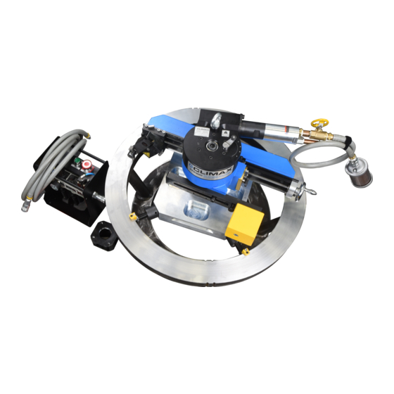
- - - - - - - - - - - - - - - - - - - - - - - - - - - - - - - - - -20 TEMS REQUIRED BUT NOT SUPPLIED EATURES AND COMPONENTS The FF5300 flange facing machine is designed for facing, beveling, and grooving operations. Principle components include: High precision in a compact design –... - Page 22 Tool Holder Axial / Radial Feed Rate Control Pneumatic Drive Motor ections Chuck Mount Counterweight Assembly nect Axial / Radial Feed Selector 2-1. FF5300 ID IGURE CHUCK ASSEMBLY 2-1. FF5300 ID ABLE CHUCK IDENTIFICATION Number Component Swiveling tool holder...
-
Page 23: Controls
2. Close the speed adjustment valve. 3. Pull the emergency stop button up. 4. Press the start button (repeat step 1 if necessary). The FF5300 controls are located on the PCU, shown in Figure 2-2 on page 12. P/N 91025, Rev. 4 Page 11... - Page 24 Shows the amount of oil in the reservoir. glass Removes foreign particulates from the air supply and protects the downstream Filter valves and motor. 1.Figure 2-2 shows the H&S quick disconnect. Your disconnect may look different. Page 12 FF5300 Operating Manual...
-
Page 25: Dimensions
2-3. P IGURE NEUMATIC ASSEMBLY the PCU. This removes all pressure from the FF5300 drive motor. The air plumbing includes an exhaust muffler to reduce the noise level and also to trap oil mist in the motor exhaust. WARNING The motor can operate unexpectedly when the air hose is connected. - Page 26 MIN SWING ø (32 INCH ARM) 22.75 INCHES [578 MM] MAX CHUCKING ø 35.8 INCHES [909 MM] MIN CHUCKING & MACHINING ø 5.7 INCHES [145 MM] 2-4. D 32" (813 IGURE IMENSIONS FOR MACHINING ARM Page 14 FF5300 Operating Manual...
- Page 27 MAX MACHINING ø (40 INCH ARM) 40 INCHES [1016 MM] MAX SWING ø (40 INCH ARM) 38.2 INCHES [970 MM] MIN SWING ø (40 INCH ARM) 26.25 INCHES [667 MM] MAX CHUCKING ø 35.8 INCHES [909 MM] MIN CHUCKING & MACHINING ø 5.7 INCHES [145 MM] 2-5.
- Page 28 2-6. D IGURE IMENSIONS SIDE VIEW Page 16 FF5300 Operating Manual...
-
Page 29: Specifications
PECIFICATIONS 2.4.1 Temperature The suggested machine ambient operating temperature is -4 – 135 F (-20 – 57 During operation, individual machine components will exceed these temperatures. During normal use, the temperature of the machine housing normally increases to about 5 F (3 C) above the ambient temperature. - Page 30 The feed rates provided in Table 2-3 are approximate and based on a free-spinning RPM of more than 40. Different RPMs, cubic feet per minute of supply air, flange material, cutting tool geometry, depth of cut, or other heavier cutting forces will reduce these feed rate values. Page 18 FF5300 Operating Manual...
-
Page 31: Feed Rate Positions
CAUTION If the feed direction selector does not move smoothly, do not force it. Stop the machine and gently work the arm back and forth while jogging the feed mechanism with the manual feed crank handle. Forcing the arm will damage the feed system, and may misalign the feed system. Setting the feed direction Do the following to set the feed direction: 1. -
Page 32: Weights
20" (508 mm) 1. All dimensions include handles and latches, if applicable. TEMS REQUIRED BUT NOT SUPPLIED The following items are required but not supplied in your CLIMAX product kit: • Measuring equipment such as tape measures, micrometers, dial indica- tors, calipers •... -
Page 33: Setup
Keep the shipping container and all packing materials for future storage and shipping of the machine. The machine ships from CLIMAX with a heavy coating of LPS 3. The recom- mended cleaner is LPS PreSolve Orange Degreaser. All parts must be cleaned before use. -
Page 34: Preparing The Machine For Use
REPARING THE MACHINE FOR USE 3.2.1 Pre-setup check The FF5300 can be set up and mounted in many ways. Before setting up the flange facer, check the following: • The machine assemblies are positioned correctly. • There is enough room to position the entire machine on or near the work piece. -
Page 35: Installation Hazards
Connect the appropriate lifting equipment to the lifting eye located on top of the main body when lifting the entire assembly. Never lift the machine by the drive motors, pneumatic lines, or hoses. DANGER Lifting the assembled machine by loose slings can cause the machine to fall from the rigging. - Page 36 (Figure 3-12), as that may cause the jacking screw to be overloaded and result in damage to the screw. If needed, add additional leg extensions to minimize the length of the threaded jacking screw that is exposed. Page 24 FF5300 Operating Manual...
-
Page 37: Configuring The Id Chuck
(481–569 mm) 22.28–25.78" (566–655 mm) 25.64–29.14" (651–740 mm) 29–32.5" (737–826 mm) 32.36–35.86" (822–911 mm) a. Leg extensions that enable the FF5300 to reach the maximum diameter range are provided regardless of the machining arm selected. P/N 91025, Rev. 4 Page 25... - Page 38 LARGE CHUCK SHOWN 6. Apply the anti-seize com- pound (provided in the tool kit) to the threads and con- tacting faces of each leg section (see Figure 3-5). 3-5. A IGURE PPLYING ANTI SEIZE COMPOUND Page 26 FF5300 Operating Manual...
- Page 39 7. Install the appropriate leg spacers (see Figure 3-6). 3-2. S ABLE TANDARD CHUCK LEG IDENTI FICATION Number Component Captive screw Setup finger Swivel gripper Chuck foot 3-6. S IGURE TANDARD CHUCK LEG COMPONENTS Jacking screw Full extension groove (not shown) 8.
-
Page 40: Installing The Id Chuck
WARNING 3-8. C IGURE HUCK CENTERED IN THE FLANGE The FF5300 is heavy and can cause personnel injury or damage if dropped. Use supplemental rigging when mounting the machine, in case it falls out or through the chucking diameter. Page 28... -
Page 41: Installing The Machining Arm
Nm) and torque to 100 ft-lbs (135 Nm). NOTICE Check that the machine is securely mounted for best machining results. NSTALLING THE MACHINING ARM The FF5300 is available with two optional machining arms, as described in Table 3-4. 3-4. O ABLE... -
Page 42: Installing The Counterweight Arm
3-10. S IGURE LIDING THE MACHINING ARM INTO PLACE NSTALLING THE COUNTERWEIGHT ARM Do the following to install the counterweight arm: 1. Lift and place the counterweight arm in the mounting position on the main body. Page 30 FF5300 Operating Manual... - Page 43 2. Pull back on the detent plunger to allow the arm to engage the M12 socket head cap screw (SHCS) in the keyhole slot. 3-11. D IGURE ETENT PLUNGER IN COUNTERWEIGHT ARM 3. Slide the arm to the desired location and tighten the M12 clamp screw plate until the arm is secured (see Figure 3-12).
- Page 44 Counterweight to be removed from the arm and bolted directly to the main housing with M12 x 140 mm SHCS (P/N 50492). There is a longer M12 screw when the counterweight is attached directly to the main body. Page 32 FF5300 Operating Manual...
-
Page 45: Centering And Leveling The Machine To The Workpiece
3-15. FF5300 (40" [1,016 IGURE MAXIMUM SWING DIAMETER 3-16. FF5300 (40" [1,016 (26.25" [667 IGURE MINIMUM SWING DIAMETER 3.10 ENTERING AND LEVELING THE MACHINE TO THE WORKPIECE Do the following to center and level the machine to the workpiece: 1. Check that power to the machine drive is isolated and locked out. -
Page 46: Rotating The Tool Head
3.11 OTATING THE TOOL HEAD Do the following to rotate the tool head: 1. Loosen the swivel head locking screws on the front of the tool post (see Figure 3-18). Page 34 FF5300 Operating Manual... -
Page 47: Swivel Head Locking Screw On The Front Of The Tool Post
CAUTION Do not loosen the tool head rapidly. Keep your hand on the tool head for stability. Quick disengagement of tool head can cause it to swing unexpectedly, and may result in personnel injury or machine damage. 2. Loosen the tool holder swivel if necessary to adjust the tool head angle. -
Page 48: Installing The Cutting Tool And Adjust Position
See Section 3.13 on page 37 when making adjustments. The feed system will only allow movement in the feed direction on the selected axis. Setting the feed direction lever in neutral (that is, vertical) position allows adjustment in either direction. Page 36 FF5300 Operating Manual... -
Page 49: Adjusting The Feed Direction , Axis , And Amount
3.13 DJUSTING THE FEED DIRECTION AXIS AND AMOUNT Do the following to adjust the feed direction, axis, and amount: 1. Use the feed selection knob to set the feed axis. Pull out for radial (that is, for fac- ing) or push in for axial (that is, for boring or tapers). - Page 50 0. This will cause serious damage to the feed mechanism and void the warranty. 3-22. F IGURE EED POSITIONS Page 38 FF5300 Operating Manual...
-
Page 51: Connecting The Air Motor To The Main Body , The Pcu, And Air Source
3.14 PCU, ONNECTING THE AIR MOTOR TO THE MAIN BODY AND AIR SOURCE Do the following to connect the air motor to main body, the PCU, and air source: 1. Install the air motor into the main body. Tighten the screws to a minimum of 20 ft-lbs (27 Nm) to secure the motor. - Page 52 This page intentionally left blank Page 40 FF5300 Operating Manual...
-
Page 53: Operation
Rotating machinery can cause serious injuries. Turn off and lock out the machine before making the pre-start checks. The FF5300 often is used in dangerous locations (in elevated positions, near other operating equipment, overhead, etc.). CLIMAX cannot foresee where this machine will be used;... -
Page 54: Machining
See Section 3.13 on page 37 for information on the feed box. DANGER To avoid serious injury to hands or arms, do not reach inside the swing of the machining arm during operation or while the machine is energized. Page 42 FF5300 Operating Manual... -
Page 55: Adjusting The Machine When The Cut Is Completed
CAUTION If the machine stops moving unexpectedly, de-pressurize and lock out the pneumatic safety valve located on the PCU before performing any troubleshooting. Refer to the PCU controls described in Section 2.2 on page 11. Do the following to operate the machine after the setup steps are complete: 1. -
Page 56: Disassembly
6. Using the supplied hoist ring, attach lifting equipment to the machine. 7. Install setup fingers to each ID chuck foot. 8. Loosen and retract the ID chuck feet. 9. Remove the machine from the work piece. Page 44 FF5300 Operating Manual... -
Page 57: Maintenance
MAINTENANCE IN THIS CHAPTER: 5.1 M - - - - - - - - - - - - - - - - - - - - - - - - - - - - - - - - - - - - - -45 AINTENANCE CHECKLIST 5.2 L - - - - - - - - - - - - - - - - - - - - - - - - - - - - - - - - - - - - - -46... -
Page 58: Ubricating The Machine
Lubricate the worm gear interface. UBRICATING THE MACHINE Table 5-3 on page 48 provides information on recommended lubricants. NOTICE The more frequently oil is used to lubricate the leadscrew and nuts, the longer they will last. Page 46 FF5300 Operating Manual... -
Page 59: Approved Lubricants
Moly Grade Anti-Seize or equivalent. PPROVED LUBRICANTS CLIMAX recommends using the following lubricants at the locations indicated. Failure to use the appropriate lubricants can result in damage and premature machine wear. P/N 91025, Rev. 4... - Page 60 414 @ 40 Moblith SHC 460 As required °C Storage Unpainted surfaces LPS 2 7 @ 25 °C As required Unpainted surfaces LPS 3 As required Moly Grade Chuck jacking screws 1 cc per screw Anti-Seize Page 48 FF5300 Operating Manual...
-
Page 61: Maintenance Tasks
PCU is lost and restored. Do the following to check the PCU drop-out circuit: 1. Check that the PCU is connected to an air supply and to the FF5300. 2. Check that the air-supply lock-out is open (pulled up). -
Page 62: Dovetail Ways Maintenance
8. Check that the machine does not automatically restart when the lock-out valve is re-opened in step 7. WARNING Do not operate the machine if the PCU starts in step 8. Contact Climax for service recommendations. 5.4.5 Dovetail ways maintenance Lightly lubricate the dovetail ways after cleaning and after each work session. -
Page 63: Troubleshooting
ROUBLESHOOTING This section is intended to help you solve basic machine performance problems. For serious maintenance or if you have questions on the following procedures, contact Climax. 5.5.1 The machine isn’t turning If the machine is not rotating, check the following: 1. -
Page 64: The Machine Is Not Cutting Flat
ECOMMISSIONING Do the following to decommission the FF5300 before disposal: 1. Drain the oil from the PCU for disposal or recycling through appropriate channels and according to local regulations. -
Page 65: Storage And Shipping
STORAGE AND SHIPPING IN THIS CHAPTER: 6.1 S - - - - - - - - - - - - - - - - - - - - - - - - - - - - - - - - - - - - - - - - - - - - - -53 TORAGE 6.1.1 S - - - - - - - - - - - - - - - - - - - - - - - - - - - - - - - - - - - -53... -
Page 66: Shipping
To decommission the flange facer prior to disposal, remove the drive assembly from the RDU and dispose of the drive assembly separately from the rest of the machine components. Refer to Appendix A for component assembly information. Page 54 FF5300 Operating Manual... -
Page 67: Appendix Aassembly Drawings
Drawing list A-1. FF5300 (P/N 89900) - - - - - - - - - - - - - - - - - - - - - - - - - - - - - - - - - - - - - - - - - - 56... -
Page 68: Igure A-1. Ff5300 Assembly (P/N 89900)
A-1. FF5300 (P/N 89900) IGURE ASSEMBLY Page 56 FF5300 Operating Manual... -
Page 69: Igure A-2. Ff5300 Assembly Detail (P/N 89900)
A-2. FF5300 (P/N 89900) IGURE ASSEMBLY DETAIL P/N 91025, Rev. 4 Page 57... -
Page 70: Igure A-3. Ff5300 Assembly Parts List 1 (P/N 89900)
A-3. FF5300 1 (P/N 89900) IGURE ASSEMBLY PARTS LIST Page 58 FF5300 Operating Manual... -
Page 71: Igure A-4. Ff5300 Assembly Parts List 2 (P/N 89900)
A-4. FF5300 2 (P/N 89900) IGURE ASSEMBLY PARTS LIST P/N 91025, Rev. 4 Page 59... -
Page 72: Igure A-5. Machining Arm Assembly (P/N 90337)
A-5. M (P/N 90337) IGURE ACHINING ARM ASSEMBLY Page 60 FF5300 Operating Manual... -
Page 73: Igure A-6. Machining Arm Assembly Parts List (P/N 90337)
A-6. M (P/N 90337) IGURE ACHINING ARM ASSEMBLY PARTS LIST P/N 91025, Rev. 4 Page 61... -
Page 74: Igure A-7. Tool Holder Assembly (P/N 89940)
A-7. T (P/N 89940) IGURE OOL HOLDER ASSEMBLY Page 62 FF5300 Operating Manual... -
Page 75: Igure A-8. Tool Holder Assembly (P/N 89940)
A-8. T (P/N 89940) IGURE OOL HOLDER ASSEMBLY P/N 91025, Rev. 4 Page 63... -
Page 76: Igure A-9. Id Chuck Assembly (P/N 89990)
10 9 A-9. ID (P/N 89990) IGURE CHUCK ASSEMBLY Page 64 FF5300 Operating Manual... -
Page 77: Igure A-10. Id Chuck Assembly Parts List (P/N 89990)
SCREW M6 X 1.0 X 30MM SHCS CAPTIVE 8 THD STAINLESS 89943 BALL SWIVEL CONTACT 90213 CHUCK HUB 5.7 TO 19 90214 CHUCK HUB 16 TO 32 90215 PLATE INTERFACE CHUCK/SPINDLE FF5300 90216 SCREW JACKING SHORT 90217 SCREW JACKING LONG 90253 NUT JACKING 1-5/8-8 EXTERNAL 90254... -
Page 78: Igure A-11. Counterweight Assembly (P/N 90252)
A-11. C (P/N 90252) IGURE OUNTERWEIGHT ASSEMBLY Page 66 FF5300 Operating Manual... -
Page 79: Igure A-12. Pneumatic Motor Assembly (P/N 90060)
A-12. P (P/N 90060) IGURE NEUMATIC MOTOR ASSEMBLY P/N 91025, Rev. 4 Page 67... -
Page 80: Able A-2. Tool Kit P/N 90350
WRENCH HEX SET 1.5 - 10MM BONDHUS BALL END 56550 WRENCH HEX 17mm LONG ARM 59626 LIFTING EYE M12 X 1.75 X 20.5 30 ID 54 OD 74 OAL 749 LBS 340 KG 60880 HAMMER DEAD BLOW 42OZ Page 68 FF5300 Operating Manual... - Page 81 Part Description number 90030 FF5300 Turning Arm Assembly, Cutting Range: 5.7 to 32 (144.8 - 812.8 mm) 89920 FF5300 Turning Arm Assembly, Cutting Range: 5.7 to 40 (144.8 - 1016 mm) 91591 Surface Finish Comparator, 2 to 500 micro in, 22 samples, w/ case.
- Page 82 Carbide Insert Replacement Kit: 91588 Includes (5EA) PN 91573 & (5EA) PN 63543. 91573 INSERT 80 DEG DIAMOND 3/8 IC 0.0079 NOSE RADIUS KC5410 63543 INSERT 80 DEG DIAMOND 3/8 IC 1/64 NOSE RADIUS KC5010 Page 70 FF5300 Operating Manual...
-
Page 83: Appendix Bsds
APPENDIX B Safety Data Sheets are available upon request. P/N 91025, Rev. 4 Page 71... - Page 84 This page intentionally left blank Page 72 FF5300 Operating Manual...
Need help?
Do you have a question about the FF5300 and is the answer not in the manual?
Questions and answers