
Subscribe to Our Youtube Channel
Related Manuals for Deif TDU 107


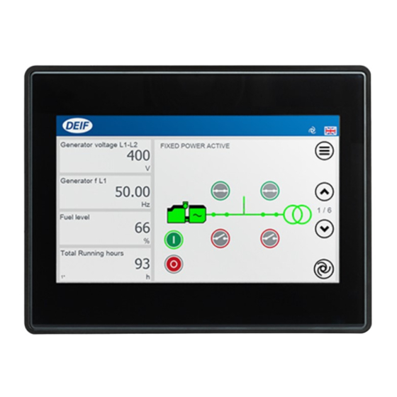
Summary of Contents for Deif TDU 107
- Page 1 Operator's manual Document no.: 4189341218C Touch Display Unit TDU 107 DEIF A/S · Frisenborgvej 33 · DK-7800 Skive · Tel.: +45 9614 9614 · Fax: +45 9614 9615 · info@deif.com · www.deif.com...
-
Page 2: Table Of Contents
1.1 About the Operator's manual ......................................1.1.1 Intended users of the Operator's manual ................................. 1.1.2 Software versions ..........................................1.1.3 List of technical documentation for TDU 107 ................................. 1.1.4 Technical support ..........................................1.1.5 Symbols for hazard statements ....................................1.1.6 Symbols for notes .......................................... - Page 3 4.10 User permissions ........................................... 4.10.1 Password levels ..........................................4.10.2 User permissions .......................................... 4.11 Display Config ..........................................4.11.1 More settings ........................................... 4.12 Language Mgt ..........................................4.13 Language translations ........................................4.13.1 Introduction ............................................4.13.2 Before you begin ........................................... 4.13.3 Create or edit language translation ..................................
-
Page 4: Introduction 1.1 About The Operator's Manual
This is the operator's manual for DEIF's Touch Display Unit, TDU 107 controlling the AGC-4 genset or mains controller. The manual is for the operator who uses the TDU 107. The manual includes an introduction to the unit, basic operator tasks, alarms, logs, and more advanced operator tasks. -
Page 5: Symbols For Hazard Statements
1.1.5 Symbols for hazard statements DANGER! This highlights dangerous situations. If the guidelines are not followed, these situations will result in death, serious personal injury, and equipment damage or destruction. WARNING This highlights potentially dangerous situations. If the guidelines are not followed, these situations could result in death, serious personal injury, and equipment damage or destruction. -
Page 6: Warnings And Safety
All trademarks are the properties of their respective owners. 1.3.2 Third party equipment DEIF takes no responsibility for the installation or operation of any third party equipment, including the genset. Contact the genset company if you have any doubt about how to install or operate the genset. -
Page 7: Disclaimer
DEIF A/S reserves the right to change any of the contents of this document without prior notice. The English version of this document always contains the most recent and up-to-date information about the product. DEIF does not take responsibility for the accuracy of translations, and translations might not be updated at the same time as the English document. -
Page 8: Overview Of The Unit
This manual applies to both TDU 107 Core and TDU 107 Extended. The software features are the same. The Touch Display Unit, TDU 107, is a touch screen solution for controlling either a DEIF AGC-4 genset or mains controller using the Ethernet port. -
Page 9: Layout
2.2 Layout 2.2.1 Unit Figure 2.2 TDU 107 layout Item Notes Touch screen area Operate the controller by touching the screen. Frame 2.2.2 Status bar Figure 2.3 Status bar Item Notes Diesel Exhaust Fluid (DEF) percentage Shows the DEF percentage. * Shows a user is logged on. -
Page 10: Core Connections
Ethernet The TDU 107 Core can be connected to the controller directly or using a switch. Use a USB type A-B cable to connect a service computer to the AGC-4 controller if the TDU Core is connected directly to the controller. - Page 11 96 97 Port 0 Port 1 In system configurations without a high data transfer connection it is possible to connect the TDU 107 Extended version directly to the controller and connect a service PC to the TDU 107. Figure 2.8...
-
Page 12: Operating The System
3. Operating the system 3.1 Menus The menu pages give you access to the features and to other menus. Figure 3.1 Example menu page Item Notes Shows available features or other menus. Features Selects feature or menu. 3.1.1 Return (back) navigation Some displays allow you to go back to the previous feature or menu. -
Page 13: Keyboards
Keyboards 3.2.1 Text keyboard You enter text information on the display by using the virtual text keyboard. Figure 3.2 Example text keyboard Item Notes Text Shows the text you are entering. Keyboard Selects letters, numbers, or symbols. Cursor Moves the cursor to the left. Moves the cursor to the right. -
Page 14: Value Keyboard
3.2.2 Value keyboard You enter number values on the display by using the virtual value keyboard. Figure 3.3 Example value keyboard Item Notes Value Shows the value you are entering. Previous value Shows the value before any changes. Minimum value Shows the minimum value you can enter. -
Page 15: Software Update Using Usb
• Software is available for both TDU 107 Core and TDU 107 Extended. Download the software for your version of the TDU 107. 2. Follow the instructions in the DEIF email to complete the software download. -
Page 16: Features
4. Features Home : Control panel Operates the system, can include mode change, open or close breakers, and start or stop the GENSET. It also provides instrument values, which can be selected by the operator. Figure 4.1 Control panel GENSET Item Notes Shows instrument values. -
Page 17: Change Instrument
4.1.1 Change instrument Changes the displayed instrument value shown on the Control panel page. Figure 4.2 Instrument selection Item Notes Instrument value to change Selects instrument to change. Refresh Refreshes the list of values. Scrolls page left. Scrolls page right. Scroll and search Searches for values. -
Page 18: Supervision
Supervision Views the state of the system in real-time. * Figure 4.3 Supervision Item Notes Live system overview Shows the system state. * Menu Opens the menu page. NOTE * Actual system shown depends upon your plant configuration. OPERATORS MANUAL 4189341218D UK Page 18 of 35... -
Page 19: Controller Settings
Controller settings Views or configures the controller parameter settings. Figure 4.4 Controller Settings Item Notes Return Returns to previous display. Search Opens search keyboard. Filter groups Opens groups of parameters. Refresh Reloads the list. Controller Settings List Scrolls settings up or down on this page. Clear filter group Clears the filter group (if used). -
Page 20: Edit Settings
4.3.1 Edit settings Edits the controller setting that was selected. NOTICE Actual controller settings The actual controller settings shown depend upon the type of setting that you are configuring. Figure 4.5 Example protection settings Item Notes Setting Shows the name of the setting. Shows the value of the setting. -
Page 21: Filter Groups
4.3.2 Filter groups Lists the filter groups you can use to filter the controller settings page. Figure 4.6 Filter groups Item Notes Shows the list of filter groups. Selects a filter group. Filter groups Returns to previous display. OPERATORS MANUAL 4189341218D UK Page 21 of 35... -
Page 22: Alarms
Alarms Views or acknowledges any alarms created in the system. Figure 4.7 Alarms Item Notes Back Returns to previous display. Acknowledge all alarms Acknowledges all unacknowledged alarms. Alarms list Scrolls the alarm list up or down. Shows the state of the alarm. Alarm state Acknowledged alarm. -
Page 23: Alarms Popup
4.4.1 Alarms popup New alarms activated in the system are shown on the alarms popup at the top of the display. Figure 4.8 Alarms popup bar Item Notes Alarm Shows the activated alarm. Alarms list Opens the Alarms list (shortcut). Alarm settings Opens the Alarm settings (shortcut). -
Page 24: Logs
Logs Shows the list of all recorded events or alarms created in the system. You can also filter, merge, or view further details on the events. Figure 4.9 Logs Item Notes Return Returns to previous display. Filters the list by either Alarms or Events only. Filter Shows only Alarms. -
Page 25: Exhaust After-Treatment Dashboard (Tier4)
Exhaust After-Treatment Dashboard (Tier4) Shows information about the Exhaust After-Treatment system. * Figure 4.10 Exhaust After-Treatment Dashboard ** Item Notes Return Returns to previous display. Shows the engine status. Engine interface status Shows an engine warning. Shows an engine shutdown. Engine emission system failure Shows an emission failure or malfunction. -
Page 26: Alternator Curve
Alternator curve Views or configures the safe operation limits for the alternator. * Figure 4.11 Alternator curve Item Notes Return Returns to previous display. Alternator curve Shows the safe operation limits for the alternator. Import (Leading) Opens the capacitive Q< configuration. Export (Lagging) Opens the inductive Q>... -
Page 27: Additional Operator Panel (Aop)
* The logic condition(s) must be configured in your M-logic project for the LED status and buttons to work. NOTE ** LED name and button name are saved locally on the TDU 107. MORE INFORMATION See the document ML-2 application notes M-Logic at https://www.deif.com/products/agc4#documentation... -
Page 28: Language
Language Selects an active language for the display. * Figure 4.13 Language Item Notes Return Returns to previous display. Shows the available active languages. Languages * Selects the language for the display. NOTE * The actual languages shown must be both installed and active to be listed for selection. MORE INFORMATION See Language Mgt for more information about how to make languages active or hidden. -
Page 29: User Permissions
4.10 User permissions 4.10.1 Password levels Table 4.1 Password level symbols Symbol Password level Symbol Password level No login required Level 1 - Customer Level 2 - Service Level 3 - Master 4.10.2 User permissions Features of the display can be restricted to the AGC-4 password levels. Figure 4.14 User Permissions Item... -
Page 30: Display Config
4.11 Display Config Views or configures the display settings. Figure 4.15 Display config Item Notes Return Returns to previous display. Shows the minimum access level required to change operation mode. Toggles through the password level required. * Change mode access level Customer Service Master... -
Page 31: More Settings
4.11.1 More settings Views or configures the additional settings for the display. Figure 4.16 More settings Item Notes Return Returns to previous display. Toggles on or off additional settings. Settings Setting enabled. Setting disabled. Screensaver Enables or disables the screensaver. Start / Stop buttons Shows or hides the start / stop buttons on the home page. -
Page 32: Language Mgt
4.12 Language Mgt Manages the display translations available on the display. Only Active languages can be used on the display. Figure 4.17 Language Mgt * Item Notes Return Returns to previous display. Import Imports all language files present on the USB device. Export Exports the selected language to the USB device. -
Page 33: Language Translations
(Provided in English) NOTE The TDU 107 only reads the AGC-4 texts at start-up. If you edit the AGC-4 texts in the Utility software, while the TDU is already running, you must restart the TDU 107 to read the new texts. -
Page 34: Create Or Edit Language Translation
◦ Example: 21. Your new language file is shown for selection. 22. Select your new language for your TDU 107 display. • The TDU 107 now reloads all the texts after confirmation. OPERATORS MANUAL 4189341218D UK... -
Page 35: End-Of-Life
In Europe, the disposal of WEEE is governed by the WEEE directive issued by the European Parliament. DEIF complies with this directive. You must not dispose of WEEE as unsorted municipal waste. Instead, WEEE must be collected separately, to minimise the load on the environment, and to improve the opportunities to recycle, reuse and/or recover the WEEE.
Need help?
Do you have a question about the TDU 107 and is the answer not in the manual?
Questions and answers