Table of Contents
Advertisement
Table of contents
1.
WARNINGS AND LEGAL INFORMATION ............... ERROR! BOOKMARK NOT DEFINED.
3.5
L
EGAL INFORMATION AND RESPONSIBILITY
3.6
E
LECTROSTATIC DISCHARGE AWARENESS
INSTALLATION/OPERATION INSTRUCTIONS
3.7
S
AFETY ISSUES
3.8
D
.................................................................... E
ISCLAIMER
3.9
D
................................................................... E
EFINITIONS
2.
APPLICATION – GAS ENGINE AND CHP CONTROL ............. ERROR! BOOKMARK NOT
DEFINED.
2.1
F
UNCTIONALITIES
2.2
S
S
COPE OF
UPPLY
2.3
N
EEDED INFORMATION FOR QUOTATIONS
3.
SOLUTION DESCRIPTION, ENGINE ....................... ERROR! BOOKMARK NOT DEFINED.
3.1
DM 400 G
–
AS
3.2
A
/
IR
FUEL MIXERS
3.3
T
HROTTLE VALVE AND ACTUATOR
3.4
D
IGITAL IGNITION CONTROL SYSTEM
3.5
A
NTI KNOCKING SYSTEM
4.
SOLUTION DESCRIPTION, RETROFITS ................ ERROR! BOOKMARK NOT DEFINED.
5.
SOLUTION DESCRIPTION, CHP ............................. ERROR! BOOKMARK NOT DEFINED.
5.1
A
VAILABLE COMBINED CONTROLS
5.2
U
SER INTERFACE
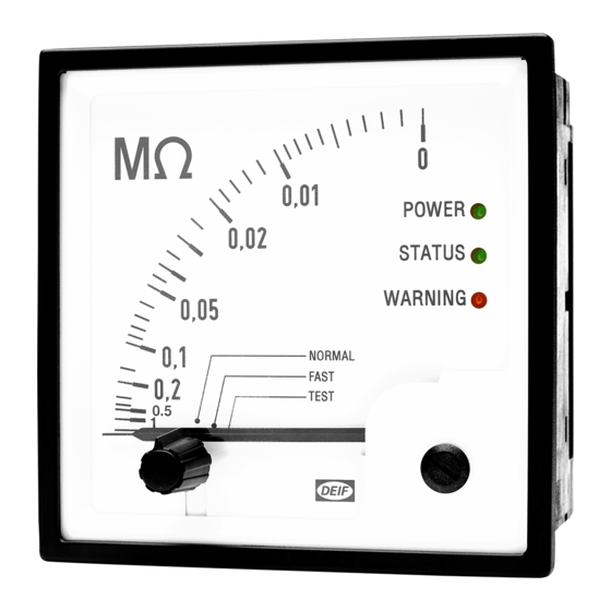
Selectable Insulation Monitor, SIM-Q MKII
............................................................... E
APPLICATION NOTES
............................................................ E
.......................................................... E
.......................... E
................................... E
MAIN CONTROLLER
............................................................. E
..................................... E
................................. E
.................................................. E
..................................... E
............................................................ E
• 3 functions: Normal, Fast and Test
• Easy adjustment and verification
• 2000 µF leakage capacitance
• Working voltage up to 690 V AC
and up to 1000 V DC
• IEC 61557-8
• Class approval
........................ E
! B
RROR
........................ E
! B
RROR
! B
RROR
! B
RROR
! B
RROR
! B
RROR
! B
RROR
! B
RROR
! B
RROR
! B
RROR
! B
RROR
! B
RROR
! B
RROR
! B
RROR
! B
RROR
.
OOKMARK NOT DEFINED
.
OOKMARK NOT DEFINED
.
OOKMARK NOT DEFINED
.
OOKMARK NOT DEFINED
.
OOKMARK NOT DEFINED
.
OOKMARK NOT DEFINED
.
OOKMARK NOT DEFINED
.
OOKMARK NOT DEFINED
.
OOKMARK NOT DEFINED
.
OOKMARK NOT DEFINED
.
OOKMARK NOT DEFINED
.
OOKMARK NOT DEFINED
.
OOKMARK NOT DEFINED
.
OOKMARK NOT DEFINED
.
OOKMARK NOT DEFINED
Document no.: 4189330024A
Advertisement
Table of Contents

Related Manuals for Deif SIM-Q MKII


Summary of Contents for Deif SIM-Q MKII
- Page 1 OOKMARK NOT DEFINED ............E SER INTERFACE RROR OOKMARK NOT DEFINED Selectable Insulation Monitor, SIM-Q MKII • 3 functions: Normal, Fast and Test • Easy adjustment and verification • 2000 µF leakage capacitance • Working voltage up to 690 V AC and up to 1000 V DC •...
-
Page 2: Table Of Contents
General purpose ...................... 4 1.2.2 Intended users ......................4 1.2.3 Contents and overall structure ................. 4 DESCRIPTION ........................5 SIM-Q MKII ................5 ENERAL DESCRIPTION OF INSTALLATION ........................6 ........................6 ONNECTION 3.1.1 Connection of AC auxiliary supply ................7 3.1.2... -
Page 3: General Information
1.1.2 Legal information and disclaimer DEIF takes no responsibility for installation or operation of the product. If there is any doubt about how to install or operate the product, please contact DEIF. The unit is not to be opened by unauthorised personnel. If opened anyway, the warranty will be lost. -
Page 4: About The Installation Instructions
SIM-Q MKII Installation/operation instructions About the installation instructions 1.2.1 General purpose The general purpose of this document is to give the user important information to be used in the installation of the unit. Make sure to read this document before starting to work with the unit. Failure to do this could result in human injury or damage to the equipment. -
Page 5: Description
The special characteristic of an IT power system is the fact that no live conductor is connected directly to earth. The SIM-Q MKII is connected to the power system by connecting the terminal marked P to one of the phases (or the neutral). The FE input is then connected to the safety cable. -
Page 6: Installation
The value of the resistor can be any value from 0 Ω to the max. allowed insulation value. The SIM-Q MKII can be supplied from the IT system under supervision, but it can also be supplied from another source, for example a 24 V DC source; see the label for supply information. -
Page 7: Connection Of Ac Auxiliary Supply
SIM-Q MKII Installation/operation instructions 3.1.1 Connection of AC auxiliary supply Type: 80 to 152 V AC Type: 176 to 288 V AC Type: 320 to 576 V AC : 100 V AC ±20 % : 220 V AC ±20 % : 400 V AC ±20 %... -
Page 8: Connection Of Dc Auxiliary Supply
SIM-Q MKII Installation/operation instructions 3.1.2 Connection of DC auxiliary supply Type: 18 to 30 V DC 0 V DC Zero 24 V DC ±25 % Label for DC version Dimensions DEIF A/S Page 8 of 18... -
Page 9: Changing The Default Settings
DIP#1 can be set to OFF (STANDARD), and the SIM-Q MKII will load its settings from a hard- coded memory area. If it is set to ON (CUSTOM), the SIM-Q MKII will load its settings from a configurable memory area that is used for custom settings and is set up by DEIF upon ordering. -
Page 10: Configuration Of The Measuring Range
Configuration of the measuring range The SIM-Q MKII can be configured for measuring range 1 MΩ to 0 MΩ (1000 to 0 kΩ) with 22 kΩ on the scale centre, or for 10 MΩ to 0 MΩ with 220 kΩ on the scale centre. The figure above shows the position of the switch for selection of either 1 MΩ... -
Page 11: Fuse
WARNING - Megger test during commissioning If the installation is to be tested by means of a high-voltage "MEGGER", the SIM-Q MKII must be disconnected at terminal "p" before testing is carried out. Ignoring this may result in damage to the SIM-Q MKII if the test voltage is higher than 1000 V AC/DC. -
Page 12: Operation
Installation/operation instructions Operation LED indicators The SIM-Q MKII is equipped with three LED indicators: two green LEDs and one yellow LED placed as the lowest one. The LED colours are as described in the table below: Power MCU not yet initialised, or no power. -
Page 13: Normal Mode
SIM-Q MKII Installation/operation instructions 4.1.1 Normal mode Start-up monitoring mode Power LED is flashing Fast measurement Warning LED is set according to insulation (Fast mode measurement) resistance and set point Status LED is flashing (1 Hz 50 % duty cycle) -
Page 14: Fast Mode
SIM-Q MKII Installation/operation instructions 4.1.2 Fast mode Power up in fault finding mode Power LED is flashing Show set point Status LED is flashing (0.5 Hz 50 % duty cycle) Meter shows the set point Relay is deactivated Warning LED is off “Power-up set point”... -
Page 15: Test Mode
Relay is activated Response time graphs The response time of the SIM-Q MKII is dependent on several different factors such as configuration, settings, capacity in the system and, of course, the resistance itself. The total response time is opposite proportional with the capacity and the resistance. This means that if great capacitance and insulation resistance is present in the application, there will be a long measuring time before the cycle is finished. -
Page 16: Technical Specifications
Graph above: Beware of response time when you select set point (Ran) in 2000 µF settings. If the installation contains frequency converters that work below 20 Hz, the SIM-Q MKII with option LF should be used instead, as it provides reliable measurements down to 5 Hz. -
Page 17: Determination Of Capacity Within An Application
SIM-Q MKII Installation/operation instructions Determination of capacity within an application Leakage capacitance in a connected network Measuring of the leakage capacitance in a connected network using a voltmeter and an ammeter (SL = PE). Single phase: CE = A/(V × 2 × phi × f). Phi is 3.14 and f is the frequency in Hz. -
Page 18: Leakage Capacitance In A Disconnected Network
Leakage capacitance using the SIM-Q MKII fault finding function The fault-finding function of the SIM-Q MKII can be used to estimate the size of the leakage capacitor. Notice that this method can only be used when no insulation error is present.
Need help?
Do you have a question about the SIM-Q MKII and is the answer not in the manual?
Questions and answers