Advertisement
Quick Links
Quick start guide
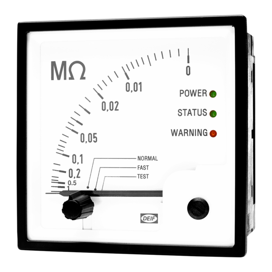
SIM-Q MKII insulation monitor
Installation
1. Make sure the SIM-Q MKII is correctly configured for the specific application.
2. For the auxiliary supply, connect the terminals to the correct voltage. See the label on the SIM-Q MKII.
3. Connect PE to ground and P to a phase. If it is a 3-phase network, then you can connect any of the phases to
P.
The recommended fuse size is maximum 2 A.
High-voltage MEGGER
If a high-voltage MEGGER is used, the SIM-Q MKII must be disconnect at terminal P before tests are
done. Failure to do so may result in damage to the SIM-Q MKII.
Adjustment of the set point
1. Turn the knob on the front of the display to TEST. The SIM-Q MKII is now in test mode.
2. The actual set point is shown on the display.
3. Go the rear of the SIM-Q MKII to adjust the set point.
During the first 10 seconds after you turn on the SIM-Q MKII, the meter pointer shows the actual set point setting
and activates its relay.
For more information:
DEIF A/S
Frisenborgvej 33, 7800 Skive, Denmark
Tel.: +45 9614 9614, info@deif.com
www.deif.com
4
WARNING
Quick start guide 4189330019C EN
Quick start guide
SIM-Q MKII insulation monitor
Default settings
Use the four jumpers on the PCB to configure the relay and change the default settings. Remove the rear cover to
access the jumpers. The jumpers are under the set pointer potentiometer.
Configure the DIP switches
• DIP #1: You can set DIP #1 to OFF (Standard) or ON (Custom). If you set the switch to OFF, the SIM-Q MKII
loads the settings from a hard-coded memory area. If set to ON, the settings are loaded from a configurable
memory area, which is configured by DEIF.
• DIP #2: You can set DIP #2 to OFF (500μF) or ON (2000 μF). The switch is used to configure the maximum
leakage capacitance.
• DIP #3: You can set DIP #3 to OFF (measuring range 0 to 1 MΩ) with 22 kΩ on the scale centre, or ON
(measuring range 0 to 10 MΩ) with 220 kΩ on the scale centre. *
• DIP #4: Use DIP #4 to configure the relay output. If you set the switch to OFF (ND), the output is a normally
de-energised contact. If you set the switch to ON (NE), the output is a normally energised contact.
NOTE
* A change of scale is necessary when you change the measuring range.
Electrostatic discharge protection
You must protect the PCB against static discharges during configuration. When the SIM-Q MKII is
installed and connected, these precautions are no longer necessary.
1
CAUTION
Quick start guide 4189330019C EN
Advertisement

Related Manuals for Deif SIM-Q MKII


Summary of Contents for Deif SIM-Q MKII
- Page 1 Configure the DIP switches • DIP #1: You can set DIP #1 to OFF (Standard) or ON (Custom). If you set the switch to OFF, the SIM-Q MKII loads the settings from a hard-coded memory area. If set to ON, the settings are loaded from a configurable memory area, which is configured by DEIF.
- Page 2 Quick start guide Quick start guide SIM-Q MKII insulation monitor SIM-Q MKII insulation monitor Wiring diagrams Mounting instructions Use the correct tools for mounting and do not exceed the recommended tightening torques. Single phase AC Single phase DC PE/FE PE/FE...
Need help?
Do you have a question about the SIM-Q MKII and is the answer not in the manual?
Questions and answers