Advertisement
Quick Links
Changing the default settings
The relay contact can be configured to function either as a normally energised contact (NE) or as a
normally de-energised contact (ND). (The original configuration is marked on the label).
Also the maximum leakage capacitance can be changed; dip switch settings are shown in Fig. 2.
Note that this will also change the measuring time.
Max. leakage capacitance
Variant no.
1µF
01, 02, 03
20µF
01, 02, 03
1µF
04, 05, 06
2µF
04, 05, 06
5µF
04, 05, 06
10µF
04, 05, 06
20µF
04, 05, 06
50µF
04, 05, 06
100µF
04, 05, 06
120µF/custom
04, 05, 06
Fig 2.
The illustrations below show the location on the PCB of the S1 switch for selection of either ND or
NE relay function (dip switch 4). The PCB is located under the rear cover.
IMPORTANT - use electrostatic discharge protection!
Sufficient care must be taken to protect the PCB against static discharges during the
configuration. Once the unit is installed and connected, these precautions are no longer
necessary.
Dip switch 1
Dip switch 2
Dip switch 3
N/A
On
N/A
N/A
Off
N/A
Off
Off
Off
On
Off
Off
Off
On
Off
On
On
Off
Off
Off
On
On
Off
On
Off
On
On
On
On
On
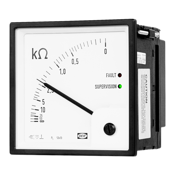
Insulation monitor, ADL-111Q96
Refer to www.deif.com for detailed information
QUICK GUIDE
Document no.: 4189330020A
Advertisement

Related Manuals for Deif ADL-111Q96


Summary of Contents for Deif ADL-111Q96
- Page 1 NE relay function (dip switch 4). The PCB is located under the rear cover. Insulation monitor, ADL-111Q96 Refer to www.deif.com for detailed information IMPORTANT - use electrostatic discharge protection! Sufficient care must be taken to protect the PCB against static discharges during the Document no.: 4189330020A configuration.
- Page 2 Use the correct tools for mounting, and do not exceed the recommended tightening torques. Aux. supply: Connect terminals to correct voltage. DEIF A/S warranty will be lost for products that are damaged because of incorrect tools used Measuring circuit: Connect PE to ground and L- to the positive or negative terminal of the for mounting, or because of excessive tightening of the terminals and screws.
Need help?
Do you have a question about the ADL-111Q96 and is the answer not in the manual?
Questions and answers