Advertisement
Quick Links
Quick start guide
AAL-2 insulation monitor
Installation
1. Make sure the AAL-2 is correctly configured for the specific application.
2. For the auxiliary supply, connect the terminals to the correct voltage.
3. Connect PE to ground and P to a phase. If it is a 3-phase network, then you can connect any of the phases to
P.
High-voltage MEGGER
If a high-voltage MEGGER is used, the ALL-2 must be disconnect at terminal P before tests are done.
Failure to do so may result in damage to the AAL-2.
Test
Test the AAL-2 in accordance with IEC 61557-8 as shown in the wiring diagrams below. Use ¼ W resistance and
set the switch ratings in accordance with the network voltages.
LINE
R S T
0
PE
2
1
3
PE
P
AAL-2
X1
X2
X3
X4
3- or 4-wire wiring diagram
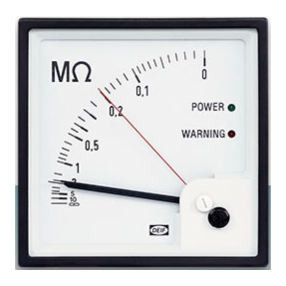
Adjustment of the set point
Use the potentiometer located on the back of the AAL-2 to adjust the warning set point. The potentiometer is in
the upper left corner. If a precise warning is necessary, connect a known resistor equal to the required setting
between P and PE. Adjust the potentiometer until the warning LED is activated.
Typical setting
Warning set point: 22 kΩ at 1 M range or 220 kΩ at 10 M range. Position the red marker pointer at the set point.
For more information:
DEIF A/S
Frisenborgvej 33, 7800 Skive, Denmark
Tel.: +45 9614 9614, info@deif.com
www.deif.com
4
WARNING
F
0
PE
2
1
3
PE
AAL-2
P
X1
X2
X3
X4
2-wire wiring diagram
Quick start guide 4189320055D EN
AAL-2
Insulation monitor
Quick start guide
Advertisement

Related Manuals for Deif AAL-2


Summary of Contents for Deif AAL-2
- Page 1 Failure to do so may result in damage to the AAL-2. Test Test the AAL-2 in accordance with IEC 61557-8 as shown in the wiring diagrams below. Use ¼ W resistance and set the switch ratings in accordance with the network voltages.
- Page 2 Quick start guide Quick start guide AAL-2 insulation monitor AAL-2 insulation monitor Warning relay Mounting instructions Use the two jumpers on the PCB to configure the warning relay. Remove the rear cover to access the jumpers. Use the correct tools for mounting and do not exceed the recommended tightening torques.
Need help?
Do you have a question about the AAL-2 and is the answer not in the manual?
Questions and answers