
Related Manuals for SEW-Eurodrive DRS 315


Summary of Contents for SEW-Eurodrive DRS 315
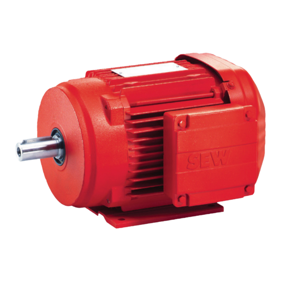
- Page 1 Drive Technology \ Drive Automation \ System Integration \ Services Explosion-Proof AC Motors – DRS/DRE/DRP 315 Operating Instructions Edition 10/2007 11631015 / EN...
- Page 2 SEW-EURODRIVE – Driving the world...
-
Page 3: Table Of Contents
Contents Contents General Information .................... 5 Structure of the safety notes ............... 5 Rights to claim under limited warranty ............6 Exclusion of liability..................6 Safety Notes ......................7 Preliminary information ................7 General information ..................7 Designated use ................... 8 Other applicable documentation .............. - Page 4 Contents Appendix......................35 Wiring diagrams ..................35 Declaration of Conformity ................. 37 Malfunctions ...................... 38 10.1 Motor malfunctions..................38 10.2 Customer service ..................39 Address List ...................... 40 Index........................49 Operating Instructions – Explosion-Proof AC Motors – DRS/DRE/DRP 315...
-
Page 5: General Information
General Information Structure of the safety notes General Information Explosion-Proof AC Motors – DRS/DRE/DRP 315 Structure of the safety notes The safety notes in these operating instructions are structured as follows: Symbol SIGNAL WORD Nature and source of hazard. Possible consequence(s) if disregarded. •... -
Page 6: Rights To Claim Under Limited Warranty
General Information Rights to claim under limited warranty Rights to claim under limited warranty Adhering to the operating instructions is a prerequisite for fault-free operation and the fulfillment of any right to claim under warranty. Read the operating instructions before you start working with the unit. -
Page 7: Safety Notes
Safety Notes Preliminary information Safety Notes The following basic safety notes must be read carefully to prevent injury to persons and damage to property. The operator must make sure that the basic safety notes are read and observed. Make sure that persons responsible for the plant and its operation, as well as persons who work independently on the unit, have read through the operating instructions carefully and understood them. -
Page 8: Designated Use
Safety Notes Designated use Designated use The electric motors are intended for industrial systems. They fulfill the applicable stan- dards and regulations: • Low Voltage Directive 73/23/EEC • Directive 94/9/EC • EN 61241-0 Electrical apparatus for use in atmospheres containing combustible dust: General requirements •... -
Page 9: Transport
Safety Notes Transport Transport Immediately upon receipt, inspect the shipment for any damage that may have occurred during transportation. Inform the shipping company immediately. It may be necessary to preclude startup. Tighten the eyebolts securely. They are only intended for the weight of the motor/gear- motor;... -
Page 10: Electrical Connection
Safety Notes Electrical connection Electrical connection All work may only be carried out by qualified personnel. During work, the low-voltage machine must be on standstill, enabled, and safeguarded against an accidental restart. This also applies to auxiliary circuits (e.g. anti-condensation heating). Check that the motor is de-energized. -
Page 11: Operation
Safety Notes Operation Operation Whenever changes occur in relation to normal operation, such as increased tempera- tures, noise, oscillation, determine the cause and contact the manufacturer, if required. Never bypass or disable protection devices, not even in test mode. If you are in doubt, switch off the motor. -
Page 12: Motor Design
Motor Design Basic design of the DR.315 Motor Design Basic design of the DR.315 The following figure illustrates the general structure. Its only purpose is to facilitate the assignment of components to the spare parts lists. Deviations are possible depending on the motor size and version! [452] [634]... -
Page 13: Nameplate, Unit Designation
Made in Germany 514903819 3.2.2 Unit designation Example: AC motor category DRS 315 S4 / 3GD Unit category Motor length and number of poles Motor size DR series with code letter "S" standard motor design Operating Instructions – Explosion-Proof AC Motors – DRS/DRE/DRP 315... -
Page 14: Mechanical Installation
Mechanical Installation Before you start Mechanical Installation NOTE Do observe the safety notes in chapter 2 (see page 7) for when installing the unit! Before you start The drive may only be installed when • the specifications on the drive's nameplate and the output voltage of the frequency inverter match the voltage supply system •... - Page 15 Mechanical Installation Mechanical installation Extended storage • Note that the service life of the lubricant in the ball bearings is reduced by 10% per of motors year after the first year of storage. • You should re-lubricate the lubrication devices on motors that have been in storage for longer than 5 years before startup.
- Page 16 Mechanical Installation Mechanical installation 4.2.2 Installing the motor • The motor or gearmotor may only be mounted or installed in the specified mounting position on a level, vibration-proof and torsionally rigid support structure. • Clean the output shafts thoroughly to ensure they are free of anti-corrosion agents (use a commercially available solvent).
-
Page 17: Electrical Installation
Electrical Installation General information Electrical Installation NOTES • Do observe the safety notes in chapter 2 (see page 7) during installation! • Use switch contacts in utilization category AC-3 according to EN 60947-4-1 for switching the motor. General information 5.1.1 Additional regulations for potentially explosive atmospheres In addition to the generally applicable installation regulations for low-voltage equipment (e.g. -
Page 18: Using Wiring Diagrams And Terminal Assignment Diagrams
Electrical Installation Using wiring diagrams and terminal assignment diagrams Using wiring diagrams and terminal assignment diagrams Connect the motor only as shown in the wiring diagram(s) included with the motor. Do not connect or start up the motor if the wiring diagram is missing. You can obtain the valid wiring diagrams free of charge from SEW-EURODRIVE. -
Page 19: Improving The Grounding (Emc)
Electrical Installation Improving the grounding (EMC) Improving the grounding (EMC) For improved, low-impedance grounding at thigh frequencies, we recommend using the following connection: 5.4.1 Size DR.315: • 1 x hex head bolt ISO 4017 M12 x 30 • 1 x washer ISO 7090 •... -
Page 20: Environmental Conditions During Operation
Electrical Installation Environmental conditions during operation Environmental conditions during operation 5.5.1 Ambient temperature The temperature range of -20 °C to 40 °C must be ensured unless specified otherwise on the nameplate. Motors intended for use in higher or lower ambient temperatures have the appropriate designation on the nameplate. -
Page 21: Motors In Category 3Gd
Electrical Installation Motors in category 3GD Motors in category 3GD 5.6.1 General information The explosion-proof/dust explosion-proof SEW-EURODRIVE motors of the DR.315 se- ries are designed for the following application zones. Motor category Area of application Application in zone 2 or 22 and compliance with the design requirements for equipment group II, category 3GD. - Page 22 Electrical Installation Motors in category 3GD 5.6.6 Protection exclusively with motor protection switch Note the following when installing the motor protection switch to EN 60947: • The motor protection switch must trip immediately in the event of a phase failure. •...
- Page 23 Electrical Installation Motors in category 3GD 5.6.9 Connecting the motor NOTE It is essential to comply with the valid wiring diagram! Do not connect or start up the motor if this wiring diagram is missing. For the wiring diagrams refer to section "Wiring diagrams" (see page 35) or request them from SEW-EURODRIVE stating the order number of the motor (see section "Unit designation, nameplate"): Checking cross...
- Page 24 Electrical Installation Motors in category 3GD Connecting the • In accordance with the wiring diagram provided motor via terminal • check cable cross section • Arrange terminal links correctly • Tighten connections and protective earth • In the terminal box: Check winding connections and tighten them if necessary Connection with ring cable rug 199641099...
- Page 25 Electrical Installation Motors in category 3GD Accessory equip- Connect accessory equipment as shown in the wiring connection diagram(s) provided ment with the motor. Do not connect or start up the accessory equipment if the wiring diagram is missing. You can obtain the valid wiring diagrams free of charge from SEW-EURODRIVE.
-
Page 26: Startup
Startup Prerequisites for startup Startup Prerequisites for startup NOTE • It is essential to observe the safety notes in section 2 (see page 7) during installation. • In case of problems, refer to section "Malfunctions" (see page 38). 6.1.1 Before startup, make sure that •... -
Page 27: Inspection/Maintenance
Inspection/Maintenance Prerequisites for startup Inspection/Maintenance Only SEW service staff, repair workshops or plants that provide the necessary expertise may repair or modify the motor. Before re-startup of the motor, make sure that all regulations are complied with and doc- ument this with a label on the motor or a written test report. NOTE ON EXPLOSION PROTECTION •... -
Page 28: Inspection And Maintenance Intervals
Inspection/Maintenance Inspection and maintenance intervals Inspection and maintenance intervals Unit/unit part Time interval Action Motor • Every 10,000 operating hours Inspect the motor: • Check ball bearings and replace if necessary • Replace the oil seal • Clean the cooling air passages Drive •... -
Page 29: Bearing Lubrication
Inspection/Maintenance Bearing lubrication Bearing lubrication 7.2.1 Bearing lubrication of the DR.315 Series 315 motors may be equipped with a lubrication device. The following figure shows the positions of the lubrication devices. 375353099 [1] Lubrication device in type A in accordance with DIN 71412 Under normal operating conditions and at an ambient temperature between -20 °C C to 40 °C, SEW-EURODRIVE uses ESSO Polyrex EM (K2P-20 DIN51825), a polyurea- based mineral high-performance, high temperature grease for the initial lubrication. -
Page 30: Reinforced Bearing
Inspection/Maintenance Reinforced bearing Relubrication The relubrication intervals for the bearing correspond to the following table for the fol- period lowing conditions: • -20 °C to + 40 °C ambient temperature • a 4-pole speed • and a normal load At greater speeds, higher loads or higher ambient temperatures, the relubrication in- tervals are shorter. -
Page 31: Inspection And Maintenance Work On The Motor Dr315
Inspection/Maintenance Inspection and maintenance work on the motor DR315 Inspection and maintenance work on the motor DR315 7.4.1 Basic design of the DR.315 The following figure is a schematic diagram. It is to facilitate assigning components to the spare parts lists. Deviations are possible depending on the motor size and version! [452] [634] [633]... - Page 32 Inspection/Maintenance Inspection and maintenance work on the motor DR315 7.4.2 Inspection steps DR.315 HAZARD! Risk of crushing if the drive starts up unintentionally. Severe or fatal injuries. • Disconnect the motor from the power supply before starting work and safeguard against accidental startup.
- Page 33 Inspection/Maintenance Inspection and maintenance work on the motor DR315 11.Mount the stator [16]. – Reseal the stator seat: seal the sealing surface with a duroplastic sealing com- pound (operating temperature -40 °C [-40 °F]...180 °C [356 °F]), such as "Hylo- mar L Spezial".
-
Page 34: Technical Data
Technical Data Permitted anti-friction bearing types Technical Data Permitted anti-friction bearing types 8.1.1 Anti-friction bearing types for motor size DR.315 A-side bearing B-side bearing Motor type IEC motor Gearmotor IEC motor Gearmotor DR.315K 6319-J-C3 6319-J-C3 DR.315S 6319-J-C3 6319-J-C3 DR.315M 6322-J-C3 6322-J-C3 DR.315L Motor with rein-... -
Page 35: Appendix
Appendix Wiring diagrams Appendix Wiring diagrams NOTE The motor must only ever be connected as shown in the wiring diagram or terminal as- signment diagram included with the motor. The following section merely contains a se- lection of the most common connection variants. You can obtain the applicable wiring diagrams from SEW-EURODRIVE free of charge. - Page 36 Appendix Wiring diagrams 9.1.2 Motor protection with TF for the DR.315 The following illustrations show the connection of the motor protection with TF PTC ther- mistor sensors or TH bimetallic thermostats. Depending on the version, an "x-pole" terminal strip is available for connecting to the trip switch.
-
Page 37: Declaration Of Conformity
Appendix Declaration of Conformity Declaration of Conformity Operating Instructions – Explosion-Proof AC Motors – DRS/DRE/DRP 315... -
Page 38: Malfunctions
Malfunctions Motor malfunctions Malfunctions 10.1 Motor malfunctions Malfunctions possible cause Remedy Motor does not start up Supply cable interrupted Check the connections and (intermediate) terminal points, correct if necessary ) Supply cable fuse has blown Replace fuse Motor protection (switch) has triggered Check that the motor protection (switch) is set correctly;... -
Page 39: Customer Service
Malfunctions Customer service Malfunctions possible cause Remedy Motor heats up excessively Overload Measure power, check project planning and use larger (measure temperature) motor or reduce load if necessary Insufficient cooling Provide for cooling air supply or clear cooling air pas- sages, retrofit forced cooling fan if necessary. -
Page 40: Address List
Address List Customer service Address List Germany Headquarters Bruchsal SEW-EURODRIVE GmbH & Co KG Tel. +49 7251 75-0 Production Ernst-Blickle-Straße 42 Fax +49 7251 75-1970 Sales D-76646 Bruchsal http://www.sew-eurodrive.de P.O. Box sew@sew-eurodrive.de Postfach 3023 • D-76642 Bruchsal Service Compe- Central SEW-EURODRIVE GmbH &... - Page 41 16, rue des Frères Zaghnoun Fax +213 21 8222-84 Bellevue El-Harrach reducom_sew@yahoo.fr 16200 Alger Argentina Assembly Buenos Aires SEW EURODRIVE ARGENTINA S.A. Tel. +54 3327 4572-84 Sales Centro Industrial Garin, Lote 35 Fax +54 3327 4572-21 Service Ruta Panamericana Km 37,5 sewar@sew-eurodrive.com.ar 1619 Garin http://www.sew-eurodrive.com.ar...
- Page 42 Address List Customer service Cameroon Sales Douala Electro-Services Tel. +237 33 431137 Rue Drouot Akwa Fax +237 33 431137 B.P. 2024 Douala Canada Assembly Toronto SEW-EURODRIVE CO. OF CANADA LTD. Tel. +1 905 791-1553 Sales 210 Walker Drive Fax +1 905 791-2999 Service Bramalea, Ontario L6T3W1 http://www.sew-eurodrive.ca...
- Page 43 Address List Customer service Czech Republic Sales Praha SEW-EURODRIVE CZ S.R.O. Tel. +420 220121234 Business Centrum Praha Fax +420 220121237 Lužná 591 http://www.sew-eurodrive.cz CZ-16000 Praha 6 - Vokovice sew@sew-eurodrive.cz Denmark Assembly Kopenhagen SEW-EURODRIVEA/S Tel. +45 43 9585-00 Sales Geminivej 28-30 Fax +45 43 9585-09 Service DK-2670 Greve...
- Page 44 Address List Customer service Hungary Sales Budapest SEW-EURODRIVE Kft. Tel. +36 1 437 06-58 Service H-1037 Budapest Fax +36 1 437 06-50 Kunigunda u. 18 office@sew-eurodrive.hu India Assembly Vadodara SEW-EURODRIVE India Private Limited Tel. +91 265 2831086 Sales Plot No. 4, GIDC Fax +91 265 2831087 Service POR Ramangamdi •...
- Page 45 Address List Customer service Lebanon Sales Beirut Gabriel Acar & Fils sarl Tel. +961 1 4947-86 B. P. 80484 +961 1 4982-72 Bourj Hammoud, Beirut +961 3 2745-39 Fax +961 1 4949-71 gacar@beirut.com Lithuania Sales Alytus UAB Irseva Tel. +370 315 79204 Naujoji 19 Fax +370 315 56175 LT-62175 Alytus...
- Page 46 Address List Customer service Peru Assembly Lima SEW DEL PERU MOTORES REDUCTORES Tel. +51 1 3495280 S.A.C. Sales Fax +51 1 3493002 Los Calderos, 120-124 Service http://www.sew-eurodrive.com.pe Urbanizacion Industrial Vulcano, ATE, Lima sewperu@sew-eurodrive.com.pe Poland Assembly Lodz SEW-EURODRIVE Polska Sp.z.o.o. Tel. +48 42 67710-90 Sales ul.
- Page 47 Address List Customer service Slovakia Banská Bystrica SEW-Eurodrive SK s.r.o. Tel. +421 48 414 6564 Rudlovská cesta 85 Fax +421 48 414 6566 SK-97411 Banská Bystrica sew@sew-eurodrive.sk Slovenia Sales Celje Pakman - Pogonska Tehnika d.o.o. Tel. +386 3 490 83-20 Service UI.
- Page 48 Address List Customer service Turkey Assembly Istanbul SEW-EURODRIVE Tel. +90 216 4419164, 3838014, 3738015 Sales Hareket Sistemleri San. ve Tic. Ltd. Sti. Fax +90 216 3055867 Service Bagdat Cad. Koruma Cikmazi No. 3 http://www.sew-eurodrive.com.tr TR-34846 Maltepe ISTANBUL sew@sew-eurodrive.com.tr Ukraine Sales Dnepropetrovsk SEW-EURODRIVE Tel.
-
Page 49: Index
Index Index Accessory equipment..........25 Improving the grounding ........19 Ambient conditions Inspection and maintenance intervals ....28 Ambient temperature .........20 Inspection/Maintenance.........27 Dust..............20 Installation..............9 Gas ..............20 Electrical ............17 Hazardous radiation...........20 Mechanical............14 Installation altitude ..........20 Installation tolerances ..........16 Vapor ..............20 Installing the motor ..........16 Anti-friction bearing types........34 Lubrication table ............34 Bearing lubrication ..........29... - Page 50 Index Safety notes Electrical connection ..........10 Installation............9 Transport..............9 Star connection ............24 Startup ..............26 Surface temperature ..........21 Technical data............34 Temperature class ..........21 Terminal box ............21 TF................25 TF temperature sensor...........25 Thermistor Category 3GD ............22 Transport..............9 Operating Instructions – Explosion-Proof AC Motors – DRS/DRE/DRP 315...
- Page 51 SEW-EURODRIVE – Driving the world...
- Page 52 Drive Technology \ Drive Automation \ System Integration \ Services How we’re driving the world With people who With comprehensive With uncompromising think fast and With a worldwide With drives and controls knowledge in virtually quality that reduces the develop the service network that is that automatically every branch of...
Need help?
Do you have a question about the DRS 315 and is the answer not in the manual?
Questions and answers