Advertisement
Table of Contents
- 1 Control Set-Up Procedures
- 2 Set-Up Codes
- 3 Exit from Set-Up Mode
- 4 Diagnostic Guide
- 5 Service Access Code
- 6 Diagnostic Test
- 7 Quick Overview Test
- 8 Manual Overview Test
- 9 Help Mode
- 10 Help Mode Symbols and Elements
- 11 Electronic Assemblies - Removal or Replacement
- 12 Wiring Diagram
- 13 Troubleshooting Guide
- Download this manual
FOR SERVICE TECHNICIAN ONLY - DO NOT REMOVE OR DESTROY
BASIC OPERATION OF EXPORT COMMERCIAL FL
WASHER, STARTING WITH MODEL 30
For additional information, see
I
www.MaytagCommercialLaundry.com
IMPORTANT
Electrostatic Discharge (ESD)
Sensitive Electronics
ESD problems are present everywhere. ESD may damage
or weaken the electronic control assembly. The new control
assembly may appear to work well after repair is finished,
but failure may occur at a later date due to ESD stress.
Use an anti-static wrist strap. Connect wrist strap to green
I
earth connection point or unpainted metal in the appliance.
Touch your finger repeatedly to a green earth connection point
or unpainted metal in the appliance.
Before removing the part from its package, touch the anti-
I
static bag to a green earth connection point or unpainted
metal in the appliance.
Avoid touching electronic parts or terminal contacts; handle
I
electronic control assembly by edges only.
When repackaging failed electronic control assembly in anti-
I
static bag, observe above instructions.
GENERAL USER INFORMATION
Scrolling 'out of order' showing in display, followed by a
failure or diagnostic code
This condition indicates the washer is inoperative.
'0 Minutes' showing in display
This condition indicates the washer cannot be operated. Coins
dropped or debit inputs during this condition will be stored in escrow
but cannot be used until normal operation is restored by opening
and closing the door. If a door switch fails, it must be replaced before
normal operation can be restored.
Cold Start (initial first use)
Washer is programmed at the factory as follows:
11 minute wash period
I
3 rinses (extra rinse not enabled)
I
$1.75 wash price (PD models)
I
$0.00 wash price (PN models)
I
Warm Start (after power failure)
A few seconds after power is restored, if a cycle was in progress
at the time of the power failure, 'RESELECT CYCLE' will flash
in the display, indicating the need for a button press to restart
the washer.
PART NO. W10340707A
-OR-
Door Lock
The door will be locked when the cycle starts. The door will remain
locked until the end of a cycle or approximately 2 minutes after a
power interruption.
Pricing
After the door is opened following the completion of a cycle,
the display indicates the cycle price (unless set for free operation).
As coins are dropped or debit inputs arrive, the display will change
to lead the user through the initiation of a cycle.
Free Cycles
This is established by setting the cycle price to zero. When this
happens, 'SELECT CYCLE' will appear rather than a cycle price.
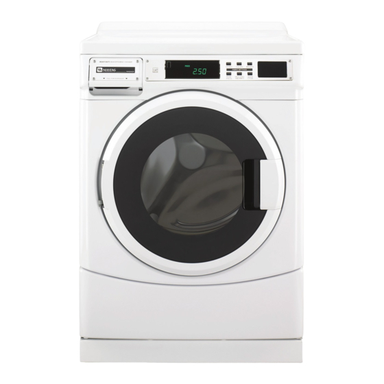
Display
After the washer has been installed and plugged in, the display will
show '0 MINUTES'. Once the washer has been plugged in and the
washer door opened and closed, the display will show the price. In
washers set for free cycles, the display will flash 'SELECT CYCLE'.
NOTE: Not displayed on washer as shown. Message scrolls
followed by the failure or diagnostic code.
PAGE 1
Advertisement
Table of Contents

Subscribe to Our Youtube Channel
Related Manuals for Maytag Commercial MHN30PD


Summary of Contents for Maytag Commercial MHN30PD
- Page 1 FOR SERVICE TECHNICIAN ONLY - DO NOT REMOVE OR DESTROY BASIC OPERATION OF EXPORT COMMERCIAL FL Door Lock WASHER, STARTING WITH MODEL 30 The door will be locked when the cycle starts. The door will remain locked until the end of a cycle or approximately 2 minutes after a For additional information, see power interruption.
-
Page 2: Control Set-Up Procedures
FOR SERVICE TECHNICIAN ONLY - DO NOT REMOVE OR DESTROY CODE EXPLANATION CONTROL SET-UP PROCEDURES 7 1 1 IMPORTANT: Read all instructions before operating. WASH LENGTH PD Models: Insert service access door key, turn, and lift to remove 7 1 1 This is the number of minutes for WASH. - Page 3 FOR SERVICE TECHNICIAN ONLY - DO NOT REMOVE OR DESTROY CODE EXPLANATION CODE EXPLANATION C .20 VALUE OF COIN 2 OPTIONS TO USE IF SPECIAL PRICING IS SELECTED (cont.): C .20 5. 0 0 This represents the value of coin 2 in the quantity of 5% TIME-OF-DAY CLOCK, MINUTES increments of the larger coin value.
-
Page 4: Exit From Set-Up Mode
FOR SERVICE TECHNICIAN ONLY - DO NOT REMOVE OR DESTROY If cycle counter (9 0C) is selected, the following is true: CODE EXPLANATION 1 00 Number of cycles in HUNDREDS. 1 02 = 200 J . C 8 COIN/DEBIT OPTION J . -
Page 5: Diagnostic Guide
FOR SERVICE TECHNICIAN ONLY - DO NOT REMOVE OR DESTROY DIAGNOSTIC GUIDE FAILURE/ERROR DISPLAY CODES Before servicing, check the following: ACCU Make sure there is power at the wall outlet. TRAC ® WASHER Are both hot and cold water faucets open and water supply INDICATION DISPLAY EXPLANATION AND RECOMMENDED PROCEDURE hoses unobstructed? - Page 6 FOR SERVICE TECHNICIAN ONLY - DO NOT REMOVE OR DESTROY ACCU ACCU TRAC ® WASHER TRAC ® WASHER INDICATION DISPLAY EXPLANATION AND RECOMMENDED PROCEDURE INDICATION DISPLAY EXPLANATION AND RECOMMENDED PROCEDURE NO WATER DETECTED ENTERING DOOR LOCK ERROR F 20 d 1 7 F 22 WASHER Washer will make several attempts to lock the door,...
- Page 7 FOR SERVICE TECHNICIAN ONLY - DO NOT REMOVE OR DESTROY ACCU ACCU TRAC ® WASHER TRAC ® WASHER INDICATION DISPLAY EXPLANATION AND RECOMMENDED PROCEDURE INDICATION DISPLAY EXPLANATION AND RECOMMENDED PROCEDURE d 2 1 F 2 7 d 1 2 F 2 5 TACHOMETER ERROR OVERFLOW CONDITIONS If the MCU is unable to properly detect motor speed,...
- Page 8 FOR SERVICE TECHNICIAN ONLY - DO NOT REMOVE OR DESTROY ACCU ACCU TRAC ® WASHER TRAC ® WASHER INDICATION DISPLAY EXPLANATION AND RECOMMENDED PROCEDURE INDICATION DISPLAY EXPLANATION AND RECOMMENDED PROCEDURE d 1 9 F 29 d 1 4 F 33 DOOR UNLOCK ERROR PUMP DISCONNECTED The door is unable to unlock after 6 tries.
- Page 9 FOR SERVICE TECHNICIAN ONLY - DO NOT REMOVE OR DESTROY ACCU ACCU TRAC ® WASHER TRAC ® WASHER INDICATION DISPLAY EXPLANATION AND RECOMMENDED PROCEDURE INDICATION DISPLAY EXPLANATION AND RECOMMENDED PROCEDURE F 73 d 1 3 d 1 3 UIC FAILURE COIN 2 ERROR Communication error within the User Interface Control.
-
Page 10: Service Access Code
FOR SERVICE TECHNICIAN ONLY - DO NOT REMOVE OR DESTROY Critical errors are indicated as part of the scrolling ‘out of order’ For PN Models: message. NOTE: Errors d5, d13, and d16 will not stop the ongoing Remove the AA1 connector from the UIC board or insert a manual cycle, although they will not allow another cycle to begin until the diagnostic card. -
Page 11: Quick Overview Test
FOR SERVICE TECHNICIAN ONLY - DO NOT REMOVE OR DESTROY QUICK OVERVIEW TEST MANUAL OVERVIEW TEST This cycle consists of 8 steps. In each step, the washer will Before replacing any system components, perform this perform a Control Action as described in the table below. Once Manual Overview Test. -
Page 12: Help Mode
FOR SERVICE TECHNICIAN ONLY - DO NOT REMOVE OR DESTROY DIAGNOSTIC TEST QUICK GUIDE The following table summarizes keypad function among the diagnostic sub-modes. Keypad Function in Diagnostic Mode Table Button Name Generic Function in Failure Function in Function in Diagnostic on Interface Button Function User Input... -
Page 13: Help Mode Symbols And Elements
FOR SERVICE TECHNICIAN ONLY - DO NOT REMOVE OR DESTROY Help Mode Submenu HELP MODE SYMBOLS AND ELEMENTS This sub-menu consists of 14 steps. Along with the 14 steps of the help mode, symbols and elements are To change to the next step, press the DELICATES AND KNITS button. mapped, at all times, to reflect the state of various inputs and outputs. -
Page 14: Electronic Assemblies - Removal Or Replacement
FOR SERVICE TECHNICIAN ONLY - DO NOT REMOVE OR DESTROY Water Valve Locations Be sure to perform the Diagnostic Tests before replacing the system components. Hot Inlet Cold Inlet Cold Inlet Valve #1 Valve #2 Valve #3 Pump Motor Continuity Test Pins Results 1 to 2... -
Page 15: Wiring Diagram
FOR SERVICE TECHNICIAN ONLY - DO NOT REMOVE OR DESTROY WIRING DIAGRAM DRIVE MOTOR Moteur d’entraînement DRAIN PUMP COLD INLET VALVES WAX MOTOR INLET VALVE Pompe Électrovannes d’entrée Moteur de l’actionneur Électrovanne de vidange d’eau froide d’entrée d’eau DOOR LOCK/SWITCH chaude Contacteur/verrou de porte Lock... -
Page 16: Troubleshooting Guide
FOR SERVICE TECHNICIAN ONLY - DO NOT REMOVE OR DESTROY TROUBLESHOOTING GUIDE PROBLEM POSSIBLE CAUSE/TEST NOTE: Possible Cause/Tests must be performed in the sequence shown for each problem. BLANK DISPLAY Possible Causes – UIC not powered or no power to the washer. –...
Need help?
Do you have a question about the MHN30PD and is the answer not in the manual?
Questions and answers