Silicon Laboratories EFR32MG12 Reference Manual
2400/434 mhz dual band 10 dbm radio board
brd4173a
Hide thumbs
Also See for EFR32MG12:
- Reference manual (24 pages) ,
- User manual (34 pages) ,
- User manual (34 pages)
Table of Contents
Advertisement
Quick Links
EFR32MG12 2400/434 MHz Dual Band
10 dBm Radio Board
BRD4173A Reference Manual
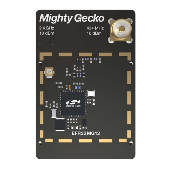
The BRD4173A Mighty Gecko Radio Board enables developers to develop Zigbee,
®
Thread, Bluetooth
Low Energy and proprietary wireless applications. The board con-
tains a dual-band Mighty Gecko Wireless System-on-Chip and it is optimized for operat-
ing at 10 dBm output power. For the 2.4 GHz band with the on-board printed antenna
and UFL connector, radiated and conducted testing is supported. For the 434 MHz
band, the on-board SMA connector enables conducted testing and attachment of exter-
nal whip antenna for radiated tests.
The BRD4173A Mighty Gecko Radio Board plugs into the Wireless Starter Kit Main-
board, which is included with the Mighty Gecko Starter Kit and gives access to display,
buttons, and additional features from Expansion Boards. With the supporting Simplicity
Studio suite of tools, developers can take advantage of graphical wireless application
development, mesh networking debug and packet trace, and visual energy profiling and
optimization. The board also serves as an RF reference design for applications targeting
2.4 GHz and 434 MHz dual band wireless operation with 10 dBm output power.
This document contains a brief introduction and description of the BRD4173A Radio
Board features, focusing on the RF sections and performance.
silabs.com | Building a more connected world.
RADIO BOARD FEATURES
• Wireless SoC:
EFR32MG12P433F1024GM48
• CPU core: ARM Cortex
®
-M4 with FPU
• Flash memory: 1024 kB
• RAM: 256 kB
• Operation frequency: 2.4 GHz + 434 MHz
• Transmit power: 10 dBm
• 2.4 GHz: Integrated PCB antenna, UFL
connector (optional)
• 434 MHz: Single SMA connector both for
transmit and receive
• Crystals for LFXO and HFXO: 32.768 kHz
and 38.4 MHz
• 8 Mbit low-power serial flash for over-the-
air updates
Rev. 1.00
Advertisement
Table of Contents

Related Manuals for Silicon Laboratories EFR32MG12


Summary of Contents for Silicon Laboratories EFR32MG12
- Page 1 EFR32MG12 2400/434 MHz Dual Band 10 dBm Radio Board BRD4173A Reference Manual The BRD4173A Mighty Gecko Radio Board enables developers to develop Zigbee, ® Thread, Bluetooth Low Energy and proprietary wireless applications. The board con- RADIO BOARD FEATURES tains a dual-band Mighty Gecko Wireless System-on-Chip and it is optimized for operat- ing at 10 dBm output power.
-
Page 2: Table Of Contents
Table of Contents 1. Introduction ....... . 4 2. Radio Board Connector ......5 2.1 Introduction. - Page 3 7.1.1 Conducted Measurements in the 434 MHz Band ....14 7.1.2 Conducted Measurements in the 2.4 GHz Band ....15 7.2 Radiated Power Measurements .
-
Page 4: Introduction
BRD4173A Reference Manual Introduction 1. Introduction The EFR32 Mighty Gecko Radio Boards provide a development platform (together with the Wireless Starter Kit Mainboard) for the Silicon Labs EFR32 Mighty Gecko Wireless System-on-Chips and serve as reference designs for the matching networks of the RF in- terfaces. -
Page 5: Radio Board Connector
EFR32MG12 data sheet. 2.2 Radio Board Connector Pin Associations The figure below shows the mapping between the connector and the EFR32MG12 pins and their function on the Wireless Starter Kit Mainboard. -
Page 6: Radio Board Block Summary
The BRD4173A Radio Board incorporates a sub-GHz matching network which connects both the sub-GHz TX and RX pins of the EFR32MG12 to the SMA connector to be able to transmit and receive with one antenna. The component values have been optimized for the 434 MHz band RF performance and current consumption with 10 dBm output power. -
Page 7: Matching Network For 2.4 Ghz
3.3.5 Matching Network for 2.4 GHz The BRD4173A Radio Board incorporates a 2.4 GHz matching network which connects the 2.4 GHz TRX pin of the EFR32MG12 to the one on-board printed Inverted-F antenna. The component values were optimized for the 2.4 GHz band RF performace and current con- sumption with 10 dBm output power. -
Page 8: Rf Section
BRD4173A Reference Manual RF Section 4. RF Section 4.1 Introduction This section gives a short introduction to the RF section of the BRD4173A Radio Board. 4.2 Schematic of the RF Matching Network The schematic of the RF section of the BRD4173A Radio Board is shown in the following figure. Path Selection 2.4 GHz Matching Network Inverted-F... -
Page 9: Bill Of Materials For The 2.4 Ghz Matching
BRD4173A Reference Manual RF Section Table 4.1. Bill of Materials for the BRD4173A Sub-GHz RF Matching Network Component Name Value Manufacturer Part Number 75 nH Murata LQW18AN75NG00D 470 nH Murata LQW18CNR47J00D 470 nH Murata LQW18CNR47J00D 18 nH Murata LQW15AN18NG00D 18 nH Murata LQW15AN18NG00D 24 nH... - Page 10 BRD4173A Reference Manual RF Section Figure 4.2. Impedance and Reflection of the Inverted-F Antenna of the BRD4173A Board Measured from the Matching Output silabs.com | Building a more connected world. Rev. 1.00 | 10...
-
Page 11: Mechanical Details
BRD4173A Reference Manual Mechanical Details 5. Mechanical Details The BRD4173A Radio Board is illustrated in the figures below. 2.4 GHz Matching Connector DC-DC LFXTAL Inductor DC-DC 2.4 GHz Path & Selection Supply EFR32xx Filter Sub-GHz Caps. 30 mm Matching Printed and Filter Inverted-F Antenna... -
Page 12: Emc Compliance
BRD4173A Reference Manual EMC Compliance 6. EMC Compliance 6.1 Introduction Compliance of the fundamental and harmonic levels of the BRD4173A Radio Board is tested against the following standards: • 434 MHz: • ETSI EN 300-220-1 • 2.4 GHz: • ETSI EN 300-328 •... -
Page 13: Applied Emission Limits For The 2.4 Ghz Band
BRD4173A Reference Manual EMC Compliance 6.5 Applied Emission Limits for the 2.4 GHz Band The above ETSI limits are applied both for conducted and radiated measurements. The FCC restricted band limits are radiated limits only. In addition, Silicon Labs applies the same restrictions to the conducted spec- trum. -
Page 14: Rf Performance
BRD4173A Reference Manual RF Performance 7. RF Performance 7.1 Conducted Power Measurements During measurements, the BRD4173A Radio Board was attached to a Wireless Starter Kit Mainboard which was supplied by USB. The voltage supply for the Radio Board was 3.3 V. 7.1.1 Conducted Measurements in the 434 MHz Band The BRD4173A Radio Board was connected directly to a Spectrum Analyzer through its SMA connector. -
Page 15: Conducted Measurements In The 2.4 Ghz Band
BRD4173A Reference Manual RF Performance 7.1.2 Conducted Measurements in the 2.4 GHz Band The BRD4173A Radio Board was connected directly to a Spectrum Analyzer through its UFL connector (the R1 resistor was removed and a 0 Ohm resistor was soldered to the R2 resistor position). The supply for the RF section (RFVDD) and the 2.4 GHz power amplifi- er (PAVDD) was 1.8 V provided by the on-chip DC-DC converter;... -
Page 16: Radiated Power Measurements
BRD4173A Reference Manual RF Performance 7.2 Radiated Power Measurements During measurements, the BRD4173A Radio Board was attached to a Wireless Starter Kit Mainboard which was supplied by USB. The voltage supply for the Radio Board was 3.3 V. The radiated power was measured in an antenna chamber by rotating the board 360 de- grees with horizontal and vertical reference antenna polarizations in the XY, XZ, and YZ cuts. -
Page 17: Radiated Measurements In The 434 Mhz Band
BRD4173A Reference Manual RF Performance 7.2.1 Radiated Measurements in the 434 MHz Band For the 434 MHz radiated power measurements, an external whip antenna (P/N: ANT-433-CW-QW-SMA) was used as a transmitter antenna. It was connected to the SMA connector of the BRD4173A Radio Board. The supply for the RF section (RFVDD) and the sub- GHz power amplifier (SUBGRF_ON, SUBGRF_OP) was 1.8 V provided by the on-chip DCDC converter (for the sub-GHz PA it was provided as VBIAS through the discrete balun);... -
Page 18: Emc Compliance Recommendations
BRD4173A Reference Manual EMC Compliance Recommendations 8. EMC Compliance Recommendations 8.1 Recommendations for 434 MHz ETSI EN 300-220-1 Compliance As shown in the previous section, the BRD4173A Mighty Gecko Radio Board with 10 dBm output power is compliant with the emission limits of the ETSI EN 300-220-1 regulation. -
Page 19: Board Revision History
BRD4173A Reference Manual Board Revision History 9. Board Revision History Table 9.1. BRD4173A Radio Board Revisions Radio Board Revision Description Initial revision. Note: The silkscreen marking on the board (e.g. PCBxxxx A00) denotes the revision of the PCB. The revision of the actual Radio Board is laser printed in the "Board Info"... -
Page 20: Errata
BRD4173A Reference Manual Errata 10. Errata There are no known errata at present. silabs.com | Building a more connected world. Rev. 1.00 | 20... -
Page 21: Document Revision History
BRD4173A Reference Manual Document Revision History 11. Document Revision History Revision 1.00 June, 2018 • Initial document revision. silabs.com | Building a more connected world. Rev. 1.00 | 21... - Page 22 Trademark Information Silicon Laboratories Inc.® , Silicon Laboratories®, Silicon Labs®, SiLabs® and the Silicon Labs logo®, Bluegiga®, Bluegiga Logo®, Clockbuilder®, CMEMS®, DSPLL®, EFM®, EFM32®, EFR, Ember®, Energy Micro, Energy Micro logo and combinations thereof, "the world’s most energy friendly microcontrollers", Ember®, EZLink®, EZRadio®, EZRadioPRO®, Gecko®, ISOmodem®, Micrium, Precision32®, ProSLIC®, Simplicity Studio®, SiPHY®, Telegesis, the Telegesis Logo®, USBXpress®, Zentri, Z-Wave, and others are trademarks or...
- Page 23 Mouser Electronics Authorized Distributor Click to View Pricing, Inventory, Delivery & Lifecycle Information: Silicon Laboratories SLWRB4173A...
Need help?
Do you have a question about the EFR32MG12 and is the answer not in the manual?
Questions and answers