Table of Contents
Advertisement
Advertisement
Table of Contents

Related Manuals for Maxon SD170EX Series


Summary of Contents for Maxon SD170EX Series
-
Page 2: Amendment Record Sheet
Service Manual SD170EX Series Amendment Record Sheet All amendments to this manual should be incorporated as soon as they are received and recorded below: Issue No. Effective Reason for Change Date Signature Date All Engineering Bulletins relevant to this product should be placed at the rear of this binder. -
Page 3: Warnings
Service Manual SD170EX Series Warnings WARNING! NEVER connect the transceiver to an AC outlet. This may pose a fire hazard or result in an electric shock. NEVER operate the radio transmitter without a suitable artificial load or antenna connected. NEVER connect the transceiver to a power source of more than 13.8V. -
Page 4: Table Of Contents
Service Manual SD170EX Series Contents Amendment Record Sheet......................2 Warnings ............................. 3 Contents ............................4 Introduction ..........................5 Pre-Install check, Accessories & Options ..................6 Pre-Installation ......................... 6 Accessories ..........................6 etc ............................6 Product Introduction ........................7 Installation ........................... 8 Installation .......................... -
Page 5: Introduction
SD170EX Series Introduction This Maxon Product Manual is a comprehensive guide to the maintenance and field repair of this equipment. It covers all versions of the SD170EX Series data radio(s). Before using this manual please read the whole of this introductory chapter, this will help you to make the best use of it. If you have not done so already, please also read the warnings immediately in front of this chapter before proceeding any further. -
Page 6: Pre-Install Check, Accessories & Options
Category C Engineering Bulletins are for improvement or modification to equipment manufactured by Maxon. Dealer / Distributor to modify affected units in the field on the next service call. Maxon will supply components free of charge. Please place these at the back of this manual and refer to them before carrying out any work. This Service Manual should be updated with any accompanying replacement pages. -
Page 7: Product Introduction
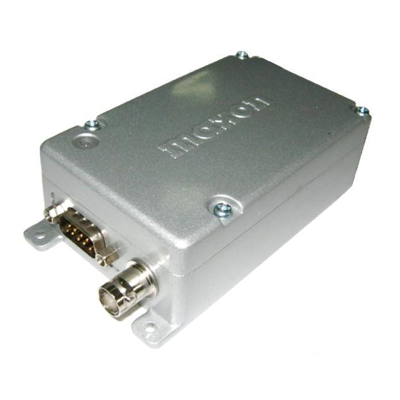
Service Manual SD170EX Series Product Introduction The SD-170EX Series (here in after called “the radios”) of RF wireless modems from MAXONCIC utilize the latest technology in its design and manufacturing. Both the UHF and VHF models are Phase Lock Loop Synthesizer (PLL) / microprocessor controlled and offer five watts of power with 16-channel capability. -
Page 8: Installation
Service Manual SD170EX Series Installation Installation The SD-170EX Series Radio Modems usually requires mounting in a suitable location. Attention should be given to the heat sinking of the radio if prolonged transmission is required; see Section 2, which also includes details of the mounting hole dimensions. -
Page 9: General Specification
Service Manual SD170EX Series General Specification Equipment Type Data radio (Wireless Modem) Data radio (Wireless Modem) Model Series SD-171EX SD-174EX Performance TIA/EIA-603 /ETS 300-113 TIA/EIA-603 /ETS 300-113 Specifications Frequency Range 142-174MHz 450-490MHz RF Output 1-5W 1-5W Channel Spacing 12.5KHz, 25KHz Programmable... -
Page 10: Transmitter Specification
Service Manual SD170EX Series Transmitter Specification Model Series SD-171EX SD-174EX Carrier Power (Nom. Max. Min.) 5W < 6W > 4.5W 5W < 6W > 4.5W Hi Power 1W<1.5W>0.8W 1W<1.5W>0.8W Low Power Sustained Transmission Time : 5 10 30 Sec Power : >90% >85% >80% Power : >90% >85% >80%... -
Page 11: Receiver Specification
Service Manual SD170EX Series Receiver Specification Model Series SD-171EX SD-174EX Sensitivity (@ 12dB SINAD) 25 KHz Channel Spacing < 0.28uV < 0.28uV 12.5 KHz Channel Spacing < 0.30uV < 0.30uV Sensitivity (1/100 Error Rate) With ACC-513 < -113dBm < -113dBm With ACC-514 <... -
Page 12: Reference Crystal
Service Manual SD170EX Series Reference Crystal SD-171EX Model Series SD-174EX 12.8MHz Frequency DV-5-2.5H1 Type Temperature ±2.5 ppm from -30° C to +60° C Characteristic < 2 ppm/ year in 1st year Aging Rate < 1 ppm/ year thereafter Enviromental Model Series :... -
Page 13: Features
Service Manual SD170EX Series Features 16 Channels The SD-170EX Series radio can store up to 16 channels within the same band. These channels can be selected by inner DIP-S/W or serial command inputted from external control system. Channel Spacing The SD-170EX Series is capable of programmable channel spacing, in both UHF and VHF bands. - Page 14 Dealer programs this feature as ON or OFF. Squelch Options Compared to existing Maxon data radios, programmable sub-audio squelch system (CTCSS & DCS) and two-tone squelch system are newly added. Each channel will have these squelch option sets during dealer programming. More detail descriptions for all available squelch systems of SD170EX are the following.
- Page 15 Service Manual SD170EX Series Sub-audio squelch system The SD-170EX Series can operate singly or with optional modem boards. Even if user wants to use sub-audio SQ system, the radio will permit this SQ option according to some cases to avoid confliction between sub-audio and data.
-
Page 16: Access To Digital And Rf Boards
Service Manual SD170EX Series Access to digital and RF boards Removing top cover Disassembly and Re-assembly of the Radio In order to carry out the following Test and Alignment procedures it will be necessary to gain access to the inside of the radio. - Page 17 Service Manual SD170EX Series Removing Screen 4. Remove the screen by carefully desoldering the screen from the RF board near to the BNC connector. 5. Then lift screen out. Page 17 of 38...
- Page 18 Service Manual SD170EX Series REMOVING & REPLACING THE RF BOARD 6. Unscrew the four holding screws from the RF board. 7. De-solder the RF lead at the BNC connection Page 18 of 38...
-
Page 19: Alignment
Service Manual SD170EX Series Alignment Transmitter Alignment Connect the unit to a Service Monitor with the power meter set to the 10 W scale (or auto range). Refer to figure 4.4 under commissioning section TCXO Set the channel selector to the mid-range frequency 460MHz (U2) and 155MHz (V2), adjust TCXO1 for a reading accurate to within ±200Hz. - Page 20 Service Manual SD170EX Series Sweep the audio frequency from 300 Hz to 4 kHz and ensure that the peak deviation does not exceed the limits shown below. If necessary adjust RV2 to vary audio deviation. 12.5 kHz channel spacing <= 2.5 kHz dev.
- Page 21 Service Manual SD170EX Series Adjust the RF output level of the RF signal generator to –47dBm and connect to the radio. Monitor the output on the audio output pin and adjust RV401 for the specific audio output level. Squelch Adjustment Before squelch adjustment is made the squelch type should be selected via software.
- Page 22 Service Manual SD170EX Series Press “SAVE” button, LED indicator will flash once. Squelch level is now set. Test for the desired level by increasing or decreasing the RF signal to levels set for open and close squelch (mute LED will be OFF & un-mute LED will be ON).
-
Page 23: Alignment Points
Service Manual SD170EX Series Alignment points Alignment Points Diagrams Page 23 of 38... -
Page 24: Flow Diagrams
Service Manual SD170EX Series Flow Diagrams Flow Diagrams RF Board Audio Amp. & Filter Audio In RSSI IF IC Pre-emphasis SA605DK Pre-Selector Level Detector High : Audio In Low : No Audio LM386 Mod Out Audio Out 300Hz HPF Data BPF 300Hz HPF Audio Amp. - Page 25 Service Manual SD170EX Series Data signal flow diagram RF Board Data In RSSI IF IC SA605DK Pre-Selector Level Audio In Detector High : Audio In Low : No Audio Mod Out Audio Out 30Hz ~ 5KHz Data BPF 4th Order...
-
Page 26: Ctcss
Service Manual SD170EX Series CTCSS CTCSS signal information Each channel supports the 38 TIA/EIA standard tone frequencies and 11 non-standard tones. All tones will be set up during dealer programming. Freq. Freq. Freq. Freq. Freq. (Hz) (Hz) (Hz) (Hz) (Hz) 67.0... -
Page 27: Interfacing
Service Manual SD170EX Series Interfacing External connections Connection is made to the SD170EX via an external 50 ohm BNC socket (RF signal) and a high density 9-way “D”-type socket (DB-9 connector; control and data signals) with 4-40 UNC threaded jack posts for more permanent connection. Besides, DB-9 Pin includes “Power”. - Page 28 Service Manual SD170EX Series Page 28 of 38...
-
Page 29: Channel Selection
Service Manual SD170EX Series Channel Selection Setting of channel selector switch for each channel Page 29 of 38... -
Page 30: Sd170Ex Layouts Control Board
Service Manual SD170EX Series SD170EX Layouts Control Board Control Board top Reference Control Board bottom Reference Page 30 of 38... - Page 31 Service Manual SD170EX Series Page 31 of 38...
- Page 32 Service Manual SD170EX Series SD171EX Layouts RF Board RF Board top reference RF Board top reference Page 32 of 38...
- Page 33 Service Manual SD170EX Series RF Board bottom Reference Page 33 of 38...
-
Page 34: Sd171Ex Layouts Rf Board
Service Manual SD170EX Series SD174EX Layouts RF Board RF Board top reference RF Board top reference Page 34 of 38... - Page 35 Service Manual SD170EX Series RF Board bottom Reference Page 35 of 38...
-
Page 36: Sd170Ex Control Schematic
Service Manual SD170EX Series SD170EX Control Schematic Page 36 of 38... -
Page 37: Sd171Ex Rf Schematic
Service Manual SD170EX Series SD171EX RF Schematic Page 37 of 38... -
Page 38: Sd174Ex Rx Schematic
Service Manual SD170EX Series SD174EX RF Schematic Page 38 of 38...
Need help?
Do you have a question about the SD170EX Series and is the answer not in the manual?
Questions and answers