Table of Contents
Advertisement
Quick Links
Advertisement
Table of Contents

Related Manuals for Maxon SD-17OEX Series


Summary of Contents for Maxon SD-17OEX Series
- Page 1 SD-17OEX SERIES SD-171EX / SD-174EX Data Radio User Instruction Manual...
- Page 2 Applications of some of the functions described in this manual are determined by the system you use. Your radio may be programmed so that you have the greatest number of functions possible relative to your needs. Should you have questions regarding the operation of the radio, please consult your Dealer and/or Maxon Australia.
-
Page 3: Specifications
Specifications GENERAL Equipment Type ……………………………………………………… Data radio Performance Specifications…………………………………………TIA/EIA-603 / ETS 300.113 Band …………………………………………………………………… VHF(SD-171E) / UHF(SD-174E) Channel Spacings …………………………………………………… 25 kHz, 12.5 kHz programmable RF Output Power …………………………………………………… 1 watt, 5 watt programmable Modulation Type …………………………………………………… F2D, F3E Intermediate Frequency …………………………………………… 45.1 MHz & 455 kHz Number of Channels …………………………………………………... -
Page 4: Transmitter Specification
TRANSMITTER Specification Carrier Power: ………………………………………………………… Nom. Max. Min. Hi ………………………………………………………………………5W < 6W > 4.5W Low ……………………………………………………………………1W < 1.5W > 0.8W Sustained Transmission …………………………………………… Nominal conditions Time : 5 10 30 Sec. Power: >90% >85% >80% Frequency Error ……………………………………………………… < 0.75 kHz Nominal condition for UHF ±5.0 ppm Extreme condition for UHF Frequency Deviation: 25 kHz Channel Spacing……………………………………………... -
Page 5: Receiver Specification
RECEIVER Specification Sensitivity (12dB Sinad) …………………………………………… Standard B.W < -118 dBm, Narrow B.W <-117 dBm @ Nom. Condition Standard B.W < -115 dBm, Narrow B.W <-114 dBm @ Extreme Condition Amplitude Characteristic....... . < ±3 dB Adjacent Channel Selectivity: 25 kHz Channel Spacing ……………………………………………... -
Page 6: Safety Information
Ø When used in a vehicle, do not mount the radio unit on or near the Airbag or Airbag activation device. Ø The use of an accessory not recommended or supplied by Maxon may cause damage to equipment or injury to personnel, and will invalidate warranty. -
Page 7: Unpacking Information
Note: The User manual is available online at www.maxon.com.au If any items are missing, please contact the Dealer from which you purchased the radios, or contact us at Maxon Australia on phone number +61 2 8707 3000. SD-171EX / SD-174EX Features •... -
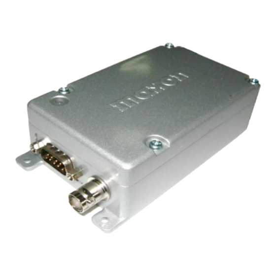
Page 8: Description Of Radio Components
Description of radio components Œ Antenna connector DE-9 connector Ž DIP-S/W Jumper selector Exterior View SW401 RV401 RV403 RV402 Digital Board... -
Page 9: Antenna Installation
Antenna installation Fasten the antenna to the radio by turning the antenna cable clockwise into the receptacle on left of radio when looking at front of radio. Powering the data radio Your data radio accepts many sources of DC power to permit more versatile use. This radio operates from 9.0V to 18V DC and standard voltage for test is 12V DC. - Page 10 SD-170EX Series Operation Channel select / SCAN Your radio‟s channel can be selected by inner DIP-S/W or serial command inputted from external control system. To change channel by inner DIP-S/W (), you should open the upper cover and then look for the DIP-S/W() on the digital board of the bottom cover.
-
Page 11: Scan Modes
Scan modes Scanning is a programmable feature that allows you to monitor a number of channels. Channel scan Once the scan list has been established, initiate scan by serial commands. If a conversation is detected on any of the channels in the scan list, the radio will stop on that channel and you will be able to hear the conversation. At that time, busy channel data is sent to external equipment or device through serial command. -
Page 12: Channel Select Switch
Channel dip switch chart C H A N N E L S W I T C H P O S I T I O N SW40 CHANNEL SELECT SWITCH Serial command Serial RX/TX Data Format (1) Asynchronous Serial Data Transfer Baud Rate : 4,800 bit/sec (3) Data Bit : 8bit , Non Parity (4) Stop Bit : 1bit... -
Page 13: Data Protocol
Data Protocol Protocol for input Serial command Protocol of data transmission from external equipment or device (: PC) to radio : External equipm ent or device Radio Input serial com m and Response Receive response Protocol for output data Protocol of data transmission from radio to external equipment or device (: PC) : External equipm ent or device Radio Output Data... - Page 14 0x66 0x00 : 1 Channel 0x66 + 0x00 0x01 : 2 Channel 0x66 + 0x01 From Radio 0x02 : 3 Channel To Pc *Only for Unmute Channel, 0x0f : 16 Channel Correct Call Channel 0x65 l It occurs when Scan Delete command comes except for Busy/Correct Call Error l...
- Page 15 User should send Channel Change Command ( 0x64,0x02 , ( 0x64 + 0x2 ) ) to Radio. If Byte2 and sum of Byte0 and Byte1 among received data are same, Radio sends ACK data to user and changes to 2 channel.
- Page 16 DB 15 PIN descriptions with input/output level D-Type Function Description Signal Type Input/ Pin No. Output Data modulation IN Signal is directly injected to MOD through data Analog signal (Tx Mod) low pass filter without pre-emphasis. 1KHz audio at 60% peak system deviation input level = 100 to 120mVrms...
- Page 17 SPARE SPARE SPARE When building a cable to interface with the SD-170E, the ground connection is made by grounding the outer shell of the DB-15 connector. Make sure the securing screws are tight on the connector when installing it to the unit...
- Page 18 Modem option for data communication DESCRIPTION The ACC-513E and ACC-514E are internal option-modems, which are applied to the SD-170EX series to increase capability for data applications. The goal of an internal modem is to improve the efficiency for data transmission and provide maximum flexibility for user applications.
- Page 19 Channel Space DTE Baud Rate Modem Baud Rate Narrow (12.5KHz) 4800 4800 4800 4800 Standard (25KHz) 9600 9600 Table 2. Available Baud rate for GMSK modem...
- Page 20 Option board pin-out chart FFSK Modem Option board Connector Input/ Function Description Output 6V to 12V Power Input Ground Signal from the digital board to transmit data key the SD- 170 transmitter TXD_EN It ensures that the radio has stabilized in transmission before the data is processed for modulation.
- Page 21 GMSK Modem Option board Connector Input/ Function Description Output 6V to 12V Power Input Ground Signal from the digital board to enable transmitter circuit of modem board. TXD_EN It ensures that the radio has stabilized in transmission before the data is processed for modulation. TX_END To finish transmission, it indicates memory buffer of Master MCU of digital board is empty.
- Page 22 Compatible accessory list ACC-513E 9600 baud GMSK modem ACC-514E 4800 baud FFSK modem ACC-516E PCB Interface - used to separate digital and RF board for alignment 593-125-SD Personality programming software ACC-2016EX Individual USB programming cable...
Need help?
Do you have a question about the SD-17OEX Series and is the answer not in the manual?
Questions and answers