Table of Contents
Advertisement
Quick Links
Advertisement
Table of Contents

Related Manuals for Genvex OPTIMA 312


Summary of Contents for Genvex OPTIMA 312
- Page 1 USER MANUAL OPTIMA 312 – ES960C circuit board...
-
Page 2: Table Of Contents
5.9 Schedule for Week Program .......................... 16 5.10 Defrosting Schedule ............................16 5.11 Set Point Schedule ............................17 6. Function ....................................18 6.1 Operation of Optima 312 ..........................18 6.2 Extra Capacity ..............................18 6.3 Operating Reliability ............................18 7. Maintenance ..................................19 7.1 Unit .................................. -
Page 3: Installation Of Optima Design
1. INSTALLATION OF OPTIMA DESIGN 1.1 Installation of the Control Panel Underneath the control panel there is access for the: A: Terminal block. Connection to main circuit board The control panel is designed to be mounted onto a level Fit a 8 x 0.25 mm2 low-current cable between the unit and wall. -
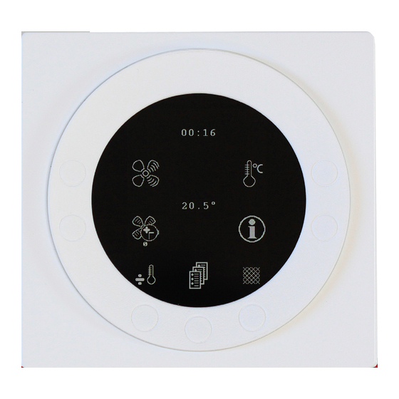
Page 4: Control Panel
4: In order for a computer to be able to read the data logs, the computer must have the Genvex data logger program installed. See the installation guide. -
Page 5: Start-Up
• Menu OK • Icon load (369) • Menu OK • Reset to default • Restarting…….. • Optima 312 UK The display will then change to: • Genvex logo • Optima 312 UK • Version number D (Control panel): X.X C (Main board): X.X... -
Page 6: Operation
Combi 185 BP type for dwellings change between + and ÷. If the symbol is set to “+”, the are supplied with the Optima 312 control unit, which has a immersion heater will automatically engage, as required. If factory setting, which means that the system can be put the symbol is set to “÷”, the immersion heater will not... -
Page 7: Main Menu
5.2 Main Menu 5.3 Date and Time There is a “Book” K4 symbol lowermost in the centre of Use this function to set and change the date and time. the screen underneath the daily operating options. It provides access to the main menu. Press this key to 01 Timer enter the main menu. -
Page 8: Calendar
5.4 Calendar 5.5 User Menu 01 – Temperature Use this function to configure and change the setting of each day of the week. Each day can be configured to run at Use this field to set the room temperature. The room different fan speeds, as required. -
Page 9: Display Menu
Setting range: Between 1 and 6 months. Input 0 in the filter your hand past the control panel. alarm to deactivate it. Note: Genvex assumes no responsibil- ity for damage that can be traced back to a deactivated filter Setting range: between 0 and 4. -
Page 10: Info Menu
12 to access items 13 to Press 2 to change all menu items to the factory settings. 18. If you forget your password, contact Genvex Service department for assistance. To change the password, enter a Note: Before carrying out a reset, make sure that the new password in this item and press “Enter”. -
Page 11: Service Menu
Current setup of operating relays Press “Arrow down” again to display the current status of the operating relays. Total time Level Compressor Level Immersion heater Level Electrical reheater Level Level Defrosting Relay 1 Compressor Domestic water Relay 2 Immersion heater Room Relay 3 Electrical reheater Extra cooling... - Page 12 Setting range for level 3: between 0 and 100%. precaution is not required, the set point can be configured Factory setting for level 3: 75%. to OFF, and the system will continue to operate. Level 4 is used, in particular, in the summer in order to lower Setting range: ON/OFF.
- Page 13 25 – Electric heating coil 29 – Stop defrosting Use this option to input if the installation is fitted with an The defrosting period ends by default when the evaporator electric heating coil: reaches a temperature of 5 °C, which is the standard setting.
- Page 14 Setting the set point to ON will lower the supply air flow Use this option to set the minimum air flow for supply air. The heat pump will not start with supply air flow below this when the fresh air temperature falls below setting.
- Page 15 44 – Preheat PI P P-band for the PI controller for the electrical modulating When using the modulating reheater, it will be necessary to preheater. replace the inlet air temperature sensor (T1) in the ventila- The P-band controls the amplification of the controller fol- tion unit with a new temperature sensor installed upstream lowing a deviation from the set point (speeder) of the reheater.
-
Page 16: Schedule For Week Program
5.9 Schedule for Week Program Monday Tuesday Wednesday Hours Minutes Speed Red. T2 Hours Minutes Speed Red. T2 Hours Minutes Speed Red. T2 Thursday Friday Saturday Hours Minutes Speed Red. T2 Hours Minutes Speed Red. T2 Hours Minutes Speed Red. T2 5.10 Defrosting Schedule Sunday Hours... -
Page 17: Set Point Schedule
5.11 Set Point Schedule Item Heading Factory setting: Configuration area Date Date Date Date (5.5) 1 Temperature 21 °C 10 - 30 °C 2 Domestic water 52 °C 0 - 55 °C 3 Immersion heater ON/OFF ON / OFF 4 Timer levels 3 and 4 ON / OFF 5 Filter change 3 months... -
Page 18: Function
6. FUNCTION 6.1 Operation of Optima 312 6.3 Operational Reliability High-pressure pressure switch A Combi unit is used for heating domestic water and supply air in order to cover the ventilation needs of the home and In order to prevent the compressor from exceeding its partial basic heating. -
Page 19: Maintenance
7. MAINTENANCE Supply air and extract air valves To achieve optimal performance, follow the instructions Clean the valves by drying with a dry cloth. below: Make sure that the valves do not turn around, causing a Before opening the unit, disconnect power / change in the air flow. -
Page 20: Troubleshooting
• After the end of the warranty period (2 years ->): the fitter that the unit was bought from or Genvex cus- tomer centre (tel.: +45 7353 2700). Have the data from the rating plate readily available (silver plate on the unit). - Page 21 – in fact you can recover up to 95% of the heat energy with a Genvex system. Please visit www.genvex.dk to see a list of our distributors KVM-Genvex A/S • Sverigesvej 6 • DK-6100 Haderslev • Tlf.: +45 73 53 27 00 • salg@genvex.dk • genvex.dk...
Need help?
Do you have a question about the OPTIMA 312 and is the answer not in the manual?
Questions and answers