
Related Manuals for Anyload 110BHM3


Summary of Contents for Anyload 110BHM3
- Page 1 110BHM3 Weigh Module Installation Guide AL-Instruction-Weigh Module-110BHM3-12/13 Page 1 of 7...
- Page 2 Contents 1. Introduction ……………………………………………………….….………3 2. Replacement Parts & Installation Tools …………….……………4 3. Installation Steps ……………………………………………………………4 4. Integral Installation ………………………………………..………………6 5. Dimensions …………………………………………………….………………7 AL-Instruction-Weigh Module-110BHM3-12/13 Page 2 of 7...
- Page 3 ● Tension loading design, no threaded connection in between. ● Self checking, patented hole design provides high repeatability. ● Multi-directional movement. ● Can withstand bigger bending and torsional force while providing a higher safety factor AL-Instruction-Weigh Module-110BHM3-12/13 Page 3 of 7...
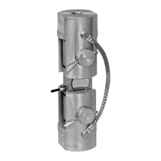
- Page 4 Put the load cell in one of the clevises, and insert the pin. Keep the load cell in the middle of clevis, do not brush with the clevis. As shown in the figure below. AL-Instruction-Weigh Module-110BHM3-12/13 Page 4 of 7...
- Page 5 The cotter pin must be okey at a time, cannot be used again and again. Step 3: Repeat step 1 and step 2. Install the second clevis to the other end of the load cell, on straight pins and cotter pin. As shown in the figure below. AL-Instruction-Weigh Module-110BHM3-12/13 Page 5 of 7...
- Page 6 Step 4: Tighten the screws to install the bonding strap. As shown in the figure below. 4/ Integral Installation Jam nut must be tightened Jam nut must be tightened 5/ Dimensions AL-Instruction-Weigh Module-110BHM3-12/13 Page 6 of 7...
- Page 7 AL-Instruction-Weigh Module-110BHM3-12/13 Page 7 of 7...
Need help?
Do you have a question about the 110BHM3 and is the answer not in the manual?
Questions and answers