GORMAN-RUPP PUMPS PRIME-AIRE Series Maintenance And Repair Manual
Hide thumbs
Also See for PRIME-AIRE Series:
- Maintenance and repair with troubleshooting (31 pages) ,
- Manual (18 pages) ,
- Maintenance and repair with troubleshooting (28 pages)
Table of Contents
Advertisement
Quick Links
Advertisement
Table of Contents

Subscribe to Our Youtube Channel
Related Manuals for GORMAN-RUPP PUMPS PRIME-AIRE Series


Summary of Contents for GORMAN-RUPP PUMPS PRIME-AIRE Series
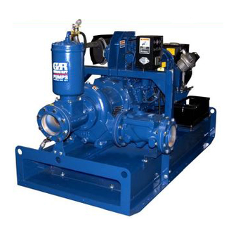
- Page 1 Use With: OM−04402 PUBLICATION NUMBER MR−05740 December 8, 2004 PRIME-AIRE SERIES PA6C Pumps THE GORMAN-RUPP COMPANY D MANSFIELD, OHIO www.gormanrupp.com GORMAN-RUPP OF CANADA LIMITED ST. THOMAS, ONTARIO, CANADA Printed in U.S.A. Copyright by the Gorman-Rupp Company...
- Page 2 The engine exhaust from this product contains chemicals known to the State of California to cause cancer, birth defects or other reproductive harm.
- Page 3 PA SERIES PUMPS MR−05740 INTRODUCTION Thank You for purchasing a Gorman-Rupp Prime- As described on the following page, this manual Aire Series priming-assisted pump. Read this will alert personnel to known procedures which re- manual carefully to learn how to safely maintain quire special attention, to those which could dam- and service your pump.
-
Page 4: Table Of Contents
MR−05740 PA SERIES PUMPS CONTENTS (Cont’d) Seal Reassembly and Installation ......... . . PAGE C −... - Page 5 PA SERIES PUMPS MR−05740 SAFETY − SECTION A following information applies gine driven units) or lock out and throughout this manual to Gorman- tag out incoming power to the con- trol box (electric motor driven Rupp Prime Aire Series pumps. units) and take precautions to en- This manual will alert personnel to sure that the pump will remain in-...
- Page 6 MR−05740 PA SERIES PUMPS ing, fingers, or tools, causing severe in- jury to personnel. After the pump has been installed, make certain that the pump and all piping or hose connections are tight, properly supported and secure before operation. Use only replacement parts provided or approved by Gorman-Rupp.
- Page 7 PA SERIES PUMPS MR−05740 The governor establishes safe operat- ing limits that should not be exceeded. Refer to the pump Performance Curve for the maximum continuous operating Never tamper with the governor on en- speed. gine driven units to gain more power. SAFETY PAGE A −...
- Page 8 MR−05740 PA SERIES PUMPS TROUBLESHOOTING − SECTION B Review all SAFETY information in Section A. Before attempting to open or service the pump: 1. Familiarize yourself with this manual. 2. Shut down the engine and discon- nect the positive battery cable (en- gine driven units) or lock out and tag out incoming power to the control box (electric motor driven units) and...
- Page 9 MR−05740 PA SERIES PUMPS TROUBLE POSSIBLE CAUSE PROBABLE REMEDY Eductor clogged. Check and clean eductor. PUMP STOPS OR FAILS TO DELIVER Air leak in suction line. Correct leak. RATED FLOW OR Lining of suction hose collapsed. Replace suction hose. PRESSURE Leaking or worn seal or pump gasket.
- Page 10 MR−05740 PA SERIES PUMPS TROUBLE POSSIBLE CAUSE PROBABLE REMEDY Cavitation in pump. Reduce suction lift and/or friction EXCESSIVE NOISE losses in suction line. Record vac- uum and pressure gauge readings and consult local representative or factory. Pumping entrained air. Locate and eliminate source of air bubble.
- Page 11 MR−05740 PA SERIES PUMPS Preventive Maintenance Schedule Service Interval* Item Daily Weekly Monthly Semi- Annually Annually General Condition (Temperature, Unusual Noises or Vibrations, Cracks, Leaks, Loose Hardware, Etc.) Pump Performance (Gauges, Speed, Flow) Bearing Lubrication Seal Lubrication (And Packing Adjustment, If So Equipped) V-Belts (If So Equipped) Air Release Valve Plunger Rod (If So Equipped)
- Page 12 MR−05740 PA SERIES PUMPS PUMP MAINTENANCE AND REPAIR − SECTION C Review all SAFETY information in Section A. either a factory-supplied or customer-supplied en- gine. Maintenance of engines and factory-supplied Follow the instructions on all tags, label and de- air compressors are detailed in separate literature cals attached to the pump.
- Page 13 MR−05740 PA SERIES PUMPS SECTION DRAWING Figure C−1. PA6C60 Pump Model Assembly Part Identification List Refer to the separate Parts List Manual for serviceable parts, part numbers and quantities. ITEM PART NAME PUMP END ASSEMBLY CHECK VALVE KIT PRIMING CHAMBER KIT NOTE: Maintenance instructions in this manual are limited to the pump hydraulic, priming and drive components only.
- Page 14 MR−05740 PA SERIES PUMPS SECTION DRAWING Figure C−2. Priming Chamber Kit Part Identification List Refer to the separate Parts List Manual for serviceable parts, part numbers and quantities. ITEM PART NAME PRIMING CHAMBER ASSEMBLY PIPE BUSHING STREET ELBOW BALL VALVE STUD HEX NUT LOCK WASHER...
- Page 15 MR−05740 PA SERIES PUMPS SECTION DRAWING Figure C−3. Priming Chamber PAGE C − 4 MAINTENANCE & REPAIR...
- Page 16 MR−05740 PA SERIES PUMPS Priming Chamber Assembly Part Identification List Refer to the separate Parts List Manual for serviceable parts, part numbers and quantities. ITEM PART NAME PRIMING VALVE −ORIFICE BUTTON HEX HD CAPSCREW LOCK WASHER STRAINER ASSEMBLY PRIMING CHAMBER PRIMING VALVE GASKET MAINTENANCE &...
- Page 17 MR−05740 PA SERIES PUMPS SECTION DRAWING Figure C−4. 66F60 Pump End Assembly PAGE C − 6 MAINTENANCE & REPAIR...
- Page 18 MR−05740 PA SERIES PUMPS 66F60 Pump End Assembly Part Identification List Refer to the separate Parts List Manual for serviceable parts, part numbers and quantities. ITEM PART NAME PUMP CASING REPAIR ROTATING ASSEMBLY HEX HEAD CAPSCREW LOCKWASHER WEAR PLATE WEAR PLATE O-RING PIPE PLUG VENTED PLUG HEX HEAD CAPSCREW...
- Page 19 MR−05740 PA SERIES PUMPS SECTION DRAWING DRIVE END VIEW Figure C−5. Repair Rotating Assembly PAGE C − 8 MAINTENANCE & REPAIR...
- Page 20 MR−05740 PA SERIES PUMPS Repair Rotating Assembly Part Identification List Refer to the separate Parts List Manual for serviceable parts, part numbers and quantities. ITEM PART NAME IMPELLER SEAL ASSEMBLY INBOARD BALL BEARING BEARING HOUSING VENTED PLUG AIR VENT RED PIPE BUSHING OUTBOARD BALL BEARING DRIVE FLANGE IMPELLER SHAFT KEY...
- Page 21 MR−05740 PA SERIES PUMPS SECTION DRAWING Figure C−6. Drive Assembly (Engine Driven Units) Part Identification List Refer to the separate Parts List Manual for serviceable parts, part numbers and quantities. ITEM PART NAME COUPLING ASSEMBLY BUSHING −KEY DRIVE FLANGE (REF) IMPELLER SHAFT (REF) LOCKWASHER SOC HD CAPSCREW...
- Page 22 MR−05740 PA SERIES PUMPS PUMP AND SEAL DISASSEMBLY the owner/maintenance personnel to ensure that only safe, established main- AND REASSEMBLY tenance procedures are used, and that any procedures not addressed in this Review all SAFETY information in Section A. manual are performed only after estab- lishing that neither personal safety nor Follow the instructions on all tags, label and de- pump integrity are compromised by...
- Page 23 MR−05740 PA SERIES PUMPS est to the orifice button and remove the pivot pin. to prevent injuries to personnel or dam- This will allow the linkage to be raised high enough age to equipment. The bail is intended to access the orifice button. for use in lifting the pump assembly only.
- Page 24 MR−05740 PA SERIES PUMPS Remove the hardware securing the drive flange (9, and wedge it between the vanes of the impeller and the pump casing to prevent rotation. Remove Figure 5) to the guard (not shown, motor driven the impeller capscrew and washer (21 and 22). units only) or bellhousing (engine driven units).
- Page 25 MR−05740 PA SERIES PUMPS Impeller Removal assembly. Disassemble the shaft and bearings only when there is evidence of wear or damage. (Figure C−5) To remove the impeller (1), unscrew it in a counter- clockwise direction (when facing the impeller). Use caution when removing the impeller;...
- Page 26 MR−05740 PA SERIES PUMPS Clean the bearings thoroughly in fresh cleaning NOTE solvent. Dry the bearings with filtered compressed The inboard bearing (3) comes from the manufac- air and coat with light oil. turer with a retaining ring installed on the bearing O.D.
-
Page 27: Seal Reassembly And Installation
MR−05740 PA SERIES PUMPS Slide the shaft and assembled bearings into the in- flammable. Use them only in a well ven- termediate bore until the inboard bearing is fully tilated area free from excessive heat, seated against the bore shoulder. Use caution not sparks, and flame. -
Page 28: Impeller Installation And Adjustment
MR−05740 PA SERIES PUMPS SPRING RETAINER O-RING SPRING CENTERING WASHER STATIONARY IMPELLER SEAT SHIMS SHAFT SLEEVE O-RING IMPELLER SHAFT SHAFT SLEEVE IMPELLER SEAL PLATE BELLOWS Figure C−8. Seal Assembly press the sleeve onto the shaft until fully seated against the shaft shoulder. Lubricate the O.D. -
Page 29: Pump Casing Installation
MR−05740 PA SERIES PUMPS shown in Figure C−6. Rotate the flexible portion of to the shaft, making future removal difficult the coupling until the tapped holes for the two set- or impossible without damage to the im- screws align with those in the bushing, and install peller or shaft. - Page 30 MR−05740 PA SERIES PUMPS er substance which may soften or otherwise dam- USE TWO USE TWO REMAINING OPPOSING ADJUSTING SCREWS age the rubber. HAND NUTS AND LOCKING COL- TO PRESS LARS TO SET FACE BACK COVER CLEARANCE INTO PUMP CASING If removed, install the guards (27, Figure C−5), and secure the drive flange to the engine bellhous- ing with the previously removed hardware (8 and...
-
Page 31: Priming Chamber Assembly And Installation
MR−05740 PA SERIES PUMPS collars to the back cover plate with the hardware linkage bar on the float bottoms against the (35 and 36). Install the two remaining hand knobs threads on the orifice button. When adjustment is snugly against the adjusting screws. complete, install and tighten the lock washer and hex nut securing the orifice button. -
Page 32: Lubrication
MR−05740 PA SERIES PUMPS Disengage the hardware (9 and 10), remove the cating a dry (overhauled) bearing housing, fill the shims (11) and reinstall the hardware (9 and 10). bearing cavity with approximately 40 ounces (1,2 liters) of oil. Clean and reinstall the air vent. Do not Reach through the suction opening and measure over-lubricate. - Page 33 For U.S. and International Warranty Information, Please Visit www.grpumps.com/warranty or call: U.S.: 419−755−1280 International: +1−419−755−1352 For Canadian Warranty Information, Please Visit www.grcanada.com/warranty or call: 519−631−2870 THE GORMAN-RUPP COMPANY D MANSFIELD, OHIO GORMAN-RUPP OF CANADA LIMITED ST. THOMAS, ONTARIO, CANADA...
Need help?
Do you have a question about the PRIME-AIRE Series and is the answer not in the manual?
Questions and answers