
Related Manuals for Pulsar DSOP24V


Summary of Contents for Pulsar DSOP24V
- Page 1 DSOP24V v.1.0 POWER SUPPLY SYSTEM DSO 24V FOR PAVIRO SYSTEM BY BOSCH Version No: 5 of 30.11.2017 Replaces version: 4 of 21.08.2017...
-
Page 2: Table Of Contents
DSOP24V TABLE OF CONTENTS 1. SYSTEM FEATURES: .......................... 4 2. TECHNICAL DESCRIPTION......................5 2.1. G DSO.................. 5 ENERAL DESCRIPTION OF THE POWER SUPPLY SYSTEM OF THE 2.2. E ................................5 LECTRICAL SCHEME 3. THE DESIGN OF THE VOICE ALARM SYSTEM................6 4. - Page 3 DSOP24V 7.2. S ..................................33 TATUS 7.3. I ................................34 NFORMATION 7.4. S ..................................34 ETTINGS 7.4.1 Date and time................................35 7.4.2 Password change................................. 35 7.4.3 The device ..................................35 7.4.4 Network settings................................36 7.4.5 SNTP settings.
-
Page 4: System Features
DSOP24V 1. System features: Compliant with the requirements of the PN-EN 54-4 Independently protected outputs for OUT1…9 and PN-EN12101-10 standards and pt. 12.2 of the amplifiers Three independently protected power supply outputs Regulation of the Minister of Interior and for ROUTER1…6 router outputs... -
Page 5: Technical Description
2.1. General description of the power supply system of the DSO. The DSOP24V power supply system is designed for uninterrupted supply of Voice Alarm Systems requiring stabilized voltage of 24V DC (-15%, +20%). The system can be equipped with a 320 - 1000W power supply unit with independently protected outputs for 5 or 9 audio amplifiers (each with 1000W power), 6 routers, and 1 controller. -
Page 6: The Design Of The Voice Alarm System
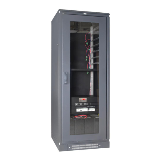
DSOP24V 3. The design of the Voice Alarm System. The design and all components of the DSO are based on the RACK 19" cabinet (Protection Class: IP30), containing all components of the system. Depending on the system and the number of devices, the height of the cabinet is adjusted individually. - Page 7 DSOP24V Table 2. Technical parameters of RACK cabinets. W=19” W=19” W=19” W=19” Mounting dimensions H=24U H=42U H=45U H=50U External dimensions 600x600x1303 600x600x2103 600x600x2236 [mm] 600x800x2459 600x800x2103 600x800x2236 [mm] [mm] [mm] Weight 66kg - 89kg - 91kg (600x600mm) (600x600mm) 152kg...
-
Page 8: Components Of The Dso Cabinet
DSOP24V 4. Components of the DSO cabinet. The equipment of each DSO cabinet includes the elements necessary for the proper operation of the system. These components, depending on their intended use, protect the electrical system against overvoltage or short circuit, supply power to the receivers, and ensure proper signaling or cooling of the installed equipment in the RACK cabinet. - Page 9 DSOP24V Fig.6. The LZ3F2B safety strip. Table 3. Components of the safety strip. Component Description Battery fuse inserts A 230V maintenance socket. The overcurrent circuit breaker of the 230V maintenance socket. Surge arresters The overcurrent circuit breaker of the power supply unit of the DSO.
-
Page 10: 230Vac Ldxxxx Voltage Distribution Terminal
DSOP24V Table 4. Technical parameters of safety strips. Model LZ1F1B LZ1F2B LZ3F1B LZ3F2B Connection to the mains Single-phase 230V 3-phase 3x230V/400V The main overcurrent circuit breaker. 1 + N-pole 3 + N-pole C16 or C20 C16 or C20 The rated short-circuit breaking... -
Page 11: The Psg3La Panel For Optical And Acoustic Indication
DSOP24V 4.3. The PSG3LA panel for optical and acoustic indication. The optional panel for optical and acoustic indication compliant with the PN-EN54-16 standard indicates the status of the entire DSO system. It is equipped with three LEDs, a sounder, and a reset button of acoustic indication. - Page 12 DSOP24V Table 7. Technical parameters of the indication panel. 10÷30V DC Supply voltage: Current consumption 30mA Optical indication LED lights: – „CONTROL” Green – „ACOUSTIC INDICATION” – „FAILURE” Yellow Acoustic indication: - Piezoelectric indicator ~60dB /1m Technical outputs: - „ACOUSTIC INDICATION”...
-
Page 13: The Rawp600Rz Fan Panel
DSOP24V 4.4. The RAWP600RZ fan panel. The DSO cabinet is equipped with a ventilation panel located in the upper part of the housing to force the air flow to the heat emitting devices. Normally, the ventilation panel is mounted in a 42U, 45U, 50U, and (optionally) 24U cabinet. -
Page 14: The Ps24Dsoxxxx Power Supply Unit
DSOP24V 5. The PS24DSOxxxx power supply unit. The PS24DSOxxxx power supply is the main component of the DSO power supply system supplying power to the controller and routers of the DSO system during normal operation (mains supply operation) and performs advanced battery charger functions. -
Page 15: Description Of Components And Electrical Contacts Of The Power Supply Unit
DSOP24V 5.2. Description of components and electrical contacts of the power supply unit. The LED display with buttons on the front panel of the power supply allows signaling the status of the power supply and displaying the basic parameters. Panel functions and operation are the same in all available models. -
Page 16: Control Panel
DSOP24V 5.3. Control panel. The power supply is equipped with a panel with buttons and a LED display that allows reading of electrical parameters and reading the status of the power supply. The panel buttons are used to select and confirm the parameter that is to be currently displayed. -
Page 17: Main Menu
DSOP24V 5.4. Main menu. The power supply has a menu from which you can view the current electrical parameters. A diagram explaining the menu structure is shown below. By default, the display shows the output voltage (section 5.4.1). Use the buttons to navigate through the following parameters in the power supply menu: the battery current indicator (section 5.4.2), the resistance of the first battery... -
Page 18: The Battery Circuit Resistance Indicator „Ra1", „Ra2
DSOP24V 5.4.3. The battery circuit resistance indicator „rA1”, „rA2” The battery circuit resistance indicator shows the measured increase in the resistance in the first "rA1" and the second "rA2" circuit of batteries connected to the power supply. The resistance is influenced by many factors. -
Page 19: The Current Failures „Flc
DSOP24V 5.4.6. The current failures „FLc” In the event of abnormal electrical parameters during operation, the power supply will indicate a failure by illuminating the corresponding LED on the panel and activating the acoustic indication (if not disabled). The power supply unit can simultaneously signal several failures at the same time. In such a case, all failure codes and their priority can be viewed in the FLc menu. -
Page 20: The List Of Failure Codes
DSOP24V 5.4.7. The list of failure codes. The power supply will indicate a failure with the appropriate code on the LED display. To identify the cause of failure, read the code found in the list below. Table 13. The list of failure codes. -
Page 21: Configuration Of Power Supply Settings
DSOP24V 5.5. Configuration of power supply settings. The power supply has a configuration menu from which you can configure the settings by changing or activating certain parameters. A diagram explaining the menu structure is shown below. Fig. 20. Power supply configuration menu. -
Page 22: Performing The Battery Test - „Tst
DSOP24V 5.5.1. Performing the battery test – „tSt” The "tSt" function runs a manual test of the batteries connected to the power supply. If the test result is negative, it will be signaled by the power supply with an appropriate message, a beeping sound, while the APS and ALARM technical outputs will change their status into opposite. -
Page 23: Setting The Eps Output Delay - "Eps
DSOP24V - Press the "OK" button - the calibration procedure is started (see section 6.2) - To return to the main menu, simultaneously press the „<,>” rightmost and leftmost buttons 5.5.3. Setting the EPS output delay - "EPS” The power supply has a programmable delay function of the 230V power failure indication. The time after... -
Page 24: Switching On / Off The „Buz"Acoustic Indication
DSOP24V 5.5.4. Switching on / off the „bUZ"acoustic indication Failures that may occur during operation of the power supply are signaled acoustically. The frequency and number of signals depends on the type of event. Table 15. Acoustic indication. Description... - Page 25 DSOP24V - The „tSt” parameter will be displayed - Use the „<” or „>” buttons in order to display the "dlS" parameter - Press „OK” - The information about the current setting will be displayed - Use the „<” or „>” buttons to set the desired option On –...
-
Page 26: Technical Inputs/Outputs Eps, Psu, Aps, Alarm, And Exti
DSOP24V 5.6. Technical Inputs/outputs EPS, PSU, APS, ALARM, and EXTi. The power supply is fitted with relay indication outputs changing state upon the occurrence of a specific event: Fig. 21. Technical outputs/inputs of the power supply. EPS – output of 230V AC power failure indication. - Page 27 DSOP24V ALARM – technical output of collective failure indication. Output indicating collective failure. In the case of failure at any EPS, APS, or PSU output or at the EXTi input, the collective failure signal ALARM will be generated.
-
Page 28: Technical Outputs - Connection With Dso Controller
DSOP24V 5.7. Technical outputs - connection with DSO controller. The technical outputs are connected with wires to the Alarm System controller. The wires can be used to connect the controller to the appropriate connector in order to monitor technical signals. -
Page 29: The Reserve Supply Circuit
DSOP24V 6. The reserve supply circuit The power supply is equipped with intelligent charging and battery control circuits that enable adequate maintenance and monitoring of their condition. The system allows connection of 1 or 2 strings (circuits) of batteries, each with up to 230Ah, which allows for a total capacity of 460Ah. -
Page 30: Battery Detection
DSOP24V - Press the "OK" button - the calibration procedure is started - To return to the main menu, simultaneously press the „<,>” rightmost and leftmost buttons The measurement of the resistance of the battery circuit is performed during the calibration process. The resistance cannot exceed 60 mΩ. -
Page 31: Remote Monitoring
DSOP24V 7. Remote monitoring. The power supply is equipped with an additional Ethernet module with a 10Base-T/100Base-TX interface to connect to the Internet. Such a configuration enables the remote monitoring of the Voice Alarm System over the Internet from anywhere. - Page 32 DSOP24V If the entered IP address is correct, the module login page will be loaded on the browser screen. Fig. 26. Ethernet module login page. If your browser does not display the above page, then check the Ethernet configuration. In particular,...
-
Page 33: Status
DSOP24V Fig. 28. The view of the Ethernet module. The following default parameters will be restored: IP address: 192.168.1.100 Administrator level: „Admin” Name: „admin” Password: User level: „User” Name: „user” Password: 7.2. Status After proper login, the main window will be loaded showing the current state of the DSO power system. The available parameters that can be read include: the voltage at the power supply output, the state of the mains supply (presence or absence), or fuse status. -
Page 34: Information
DSOP24V 7.3. Information The "Information" tab” is presented below. The presented parameters are read-only. Meaning of the menu items: Date and time - date and time of the power supply unit of the DSO Software version - Version of the software controlling the PSU and Ethernet server... -
Page 35: Date And Time
DSOP24V 7.4.1 Date and time. After entering the "Date and Time" settings, a window where you can set the system clock date and time is displayed. Fig. 32. Setting the date and time of the power supply. – The current time of the system clock of the power supply. -
Page 36: Network Settings
DSOP24V Fig. 34. Name change. 7.4.4 Network settings. Select the "Network settings" for access to the network parameters enabling the communication with the power supply. Fig. 35. Network settings. – automatic IP address assignment. Once selected, the IP address will be automatically assigned DHCP to the PSU from a pool of free addresses each time the power is turned on. -
Page 37: Email
DSOP24V 7.4.6 Email. The DSO power supply allows sending email notifications to 2 recipients when a specific event occurs. The function includes SSL-encrypted SMTP user authentication to maintain the security of your mail account. After choosing the "E-mail" option, you can configure email client parameters. -
Page 38: Graphs
DSOP24V 7.5. Graphs The "Graphs" tab allows you to read the history of parameters (current, voltage, resistance in the battery circuit, and temperature) in the form of graphs stored in the memory of the power supply. During normal operation, the power supply registers the electrical parameters both at the output and battery circuits and then stores them in the internal non-volatile memory. -
Page 39: History
DSOP24V The program allows you to save data from the graphs for later analysis. By pressing the "Save to file" button, the data is saved in the "csv" format, the individual columns are separated with a semicolon. The saved files can be accessed by spreadsheets. -
Page 40: Update
Otherwise, the imported text may be incorrectly recognized. 7.7. Update. The power supply unit supports the software update function via a file downloaded at www.pulsar.pl. To update the power supply software you must: - Download the latest version of the file at the www.pulsar.pl... -
Page 41: The Confi-Dso Program For Designers
PVA-2P500 amplifier, PVA-4CR12 controller, PVA-4R24 router, and the PVA-15CST microphone with keypad extension. The program will calculate all parameters based on the mentioned units even though they are not included in the DSOP24V power supply system. Enter the number of devices to be installed in the corresponding fields. - Page 42 DSO by an automatically generated string of digits. The "Documentation" button opens an additional window listing the available technical documentation of the DSO. Selecting any option redirects you to the PULSAR website from which the requested document, e.g.: operating instructions, data sheet, certificate, etc., will be downloaded.
- Page 43 DSOP24V Fig. 43. Technical information on the DSO. Fig. 44. The summary of DSO configurations.
- Page 44 DSOP24V The DESCRIPTION field includes the price summary and is the summary of the configured DSO including additional components such End of Line (EOL) Supervision Board and Firefighter's Microphone Power Supply Unit. Fig. 45. The price summary of DSO.
-
Page 45: Technical Parameters
DSOP24V 9. Technical parameters. Parameters of the DSO system (Table 16). Electrical parameters of the DSO (Table 17). Safety of Use (Table 18). Operation parameters (Table 19). Table 16. Parameters of the DSO system. Functional class: PN-EN 12101-10:2007 230V/400V mains connection... -
Page 46: Table 18. Safety Of Use
DSOP24V replacement U<20V (± 2%) – disconnection (+BAT) of the batteries Under-voltage protection (UVP). Technical outputs: - EPS; output indicating AC power failure - Type – relay - APS; output indicating battery failure - PSU; output indicating PSU failure - ALARM;... -
Page 47: Installation
230/400V AC and low-voltage installations. The installer should be trained in commissioning and operation of the power supply system of the DSO by the Pulsar company. The electrical system shall follow valid standards and regulations. The DSO cabinet should be mounted in such a way to provide both front and rear access for service personnel. - Page 48 DSOP24V Fig.47. Connection to the power system – 3-phase 400V AC connection. The shock protection circuit shall be performed with a particular care, i.e. the yellow and green wire coat of the power cable shall stick to one side of the terminal marked with the PE symbol. Operation of the PSU without the properly made and fully operational shock protection circuit is UNACCEPTABLE! It can cause a device failure or an electric shock.
-
Page 49: The Procedure For Checking The Dso
DSOP24V 10.3. The procedure for checking the DSO. 1. Check the indication displayed on the front panel of the power supply unit: a) On the LED display (see section 5.3) the power supply should indicate a voltage in the range of 22 ÷... -
Page 50: Technical Inspections And Maintenance
DSOP24V 11. Technical inspections and maintenance. Technical inspections and maintenance can be performed after disconnecting the power supply of the DSO from the power network The PSU does not require any specific maintenance; however, its interior should be cleaned with compressed air if used in dusty conditions. In the case of fuse replacement, use a replacement of the same parameters. - Page 51 The data can be read remotely or locally by employees of the PULSAR company In the case of unjustified claim, the claimant may be charged with the travel and manhour costs of a PULSAR employee incurred by the PULSAR company.
Need help?
Do you have a question about the DSOP24V and is the answer not in the manual?
Questions and answers