Table of Contents
Advertisement
Advertisement
Table of Contents

Related Manuals for WEBTEC HPM


Summary of Contents for WEBTEC HPM
-
Page 2: Foreword
Products Limited - behält sich das Recht vor, Verbesserungen oder Änderungen der Spezifikationen ohne Ankündigung vorzunehmen. Webtec Products Limited - se réserve le droit d'améliorer et de changer ses spécifications sans préavis. Webtec Products Limited - se reserva el derecho de realizar mejoras y cambios a las especificaciones sin previo aviso. V2.0/02.11... - Page 3 Foreword V2.0/02.11...
-
Page 4: Table Of Contents
Contents Contents Foreword Revisions Notes on safety/product selection Approved use Skilled personnel Accuracy of the technical documentation High-pressure applications Service/repair Notes on disposal Device version/range of supply Initial use Charging the batteries/battery status indicator Replacing the batteries Keys and functions Symbols and using the menus Connecting the sensors/display functions Display format (DISP) Display configuration (LINE) Zero point calibration (ZERO) Deleting MIN/MAX values (RESET) - Page 5 Contents Device settings (SET) Setting the units (SET-UNIT) Auto power off (SET-AUTO POWER) Setting auxiliary sensors (SET-AUX. SENSOR) Displaying defined measurement tasks (SET-PROJECT) Setting the contrast (SET-CONTRAST) Setting the time/date (SET-TIME/DATE) Displaying the device version (SET-VERSION) Factory setting (USER RESET) Configuring the measured value memory (MEMORY SET) Deleting measured value memory (MEM-DELETE MEMORY) Setting the data format (MEM-DATA FORMAT)
-
Page 6: Notes On Safety/Product Selection
Notes on safety/product selection Notes on safety/product selection 1.1 Approved use The device is approved for use in applications described in the Operat- ing Instructions only. Any other use is not approved and can lead to accidents or the destruction of the device. Non-approved use will result in the immediate expiry of all guarantee and warranty claims against the manufacturer. -
Page 7: Service/Repair
All devices that fall under the directive must feature this logo: Can we be of assistance? Webtec offers you the option of returning your old device to us at no ex- tra charge. Webtec will then professionally recycle and dispose of your device in accordance with the applicable law. - Page 8 What do you have to do? Once your device has reached the end of its service life, simply return it by parcel service (in the box) to your Webtec sales branch responsible for customer care - we will then initiate the necessary recycling and dis- posal measures.
-
Page 9: Device Version/Range Of Supply
Device version/range of supply Device version/range of supply The measuring instrument and sensors enable the user to measure all relevant parameters in a hydraulic system. Parameters: • [bar/psi] Pressure, Dp (load sensing pumps) • [°C/°F] Temperature • [L/min/G/min] (U.S) volumetric flow rate • [1/min] RPM Automatic sensor recognition means the measuring instrument is simple to operate. -
Page 10: Initial Use
Initial use Initial use The measuring instrument is supplied with rechargeable batteries fitted at the factory. Charge the rechargeable batteries for at least 3 hours before using for the first time. The device is then ready for use. 3.1 Charging the batteries/battery status indicator If the battery power is too low, the battery symbol flashes and the meas- uring instrument turns off automatically. -
Page 11: Keys And Functions
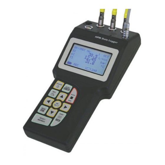
Keys and functions Keys and functions A 11-30 VDC power supply unit 110/220 VAC-15 VDC Car adapter 12/24 VDC B I1 . . I4 Sensor ports C PC (USB) D Display E Keypad V2.0/02.11... - Page 12 Keys and functions Function keys ON/OFF Confirms function/value Selects function/value STOP/ESC Menu keys * These menu keys are assigned dual functions: Assignment 1. Menu level = 1 x press Assignment 2. Menu level (black background) = 1 x hold key pressed down (2 s) ZERO Zero point calibration IN1 = IN2...
-
Page 13: Symbols And Using The Menus
Keys and functions 4.1 Symbols and using the menus If the the sign '>' is displayed at the end of a menu function, press the OK key to enter an associated submenu. If the sign ':' is displayed, press the OK key to confirm the respec- tive entry. - Page 14 Keys and functions As the function keys are easy to understand and always function in the same manner, actuating the function keys has not been included in the example sequences to ensure that the content of the menus remain central to the descriptions. It is a pre-condition for replicating the examples that the function keys are used as described above.
-
Page 15: Connecting The Sensors/Display Functions
Connecting the sensors/display functions Connecting the sensors/display functions To avoid electrical interference, please observe the following steps: 1 Connect the sensor to the measuring instrument using the connec- tion cable. 2 Turn on the measuring instrument. Measuring instrument with two pressure sensors • Once turned on, all measured values are visible in the display. •... -
Page 16: Display Format (Disp)
Connecting the sensors/display functions • The following message will be displayed if no sensor is connected to the device: 5.1 Display format (DISP) Press DISP (once) It is possible to change the display format by pressing DISP (once only). Available for selection: = Actual values = Minimum values MAX = Maximum values (pressure spikes) = Full scale (upper range value) -
Page 17: Display Configuration (Line)
Connecting the sensors/display functions 5.2 Display configuration (LINE) Press and hold LINE (2 s) Line: 1: No setting possible cannot be selected Available for selection: Difference (IN1 - IN2) Addition (IN1 + IN2) Volume VOL= Q3 x time Available for selection: Power PWR1 = p1 x Q3 PWR2 = (p1-p2) x Q3 V2.0/02.11... -
Page 18: Zero Point Calibration (Zero)
Connecting the sensors/display functions 5.3 Zero point calibration (ZERO) If the alignment values If the alignment values are within the permissi- exceed the permissible ble tolerance tolerance (2 % of FS), (2 % of FS), the values the following is dis- are set to zero. played: ZERO OFL. Press ZERO (once) V2.0/02.11... -
Page 19: Deleting Min/Max Values (Reset)
Connecting the sensors/display functions 5.4 Deleting MIN/MAX values (RESET) The MAX values measured until now are displayed in the MAX display. Deleting MIN/MAX values. The updated MAX values are displayed in the MAX display. Example: Loss of pressure in the hydraulic system 5.5 Differential value display ► The settings IN1 – IN2 are described in the chapter 'Display configu- ration (LINE)'. -
Page 20: Differential Value Alignment (In1=In2)
Connecting the sensors/display functions 5.6 Differential value alignment (IN1=IN2) Press and hold IN1=IN2 (2 s) Carry out differential value alignments at below operating pres- sure. Connect two pressure sensors to the same connection (T-adapter). ∆p-calibration sets the tolerance of the sensors in relation to one another to zero. This setting remains stored;... - Page 21 Connecting the sensors/display functions Three error messages are possible for IN1=IN2: 1 Alignment values exceed the permissible tolerance: For sensors with automatic sensor recognition, 5 % of the upper range value (FS) For auxiliary sensors, 10 % of the upper range value (FS) 2 IN1 - IN2 is not configured (DISP-LINE): 3 Measured variables are not the same (IN1=bar/IN2=L/min) V2.0/02.11...
-
Page 22: Connecting Auxiliary Sensors (Set Aux. Sensor)
Connecting the sensors/display functions 5.7 Connecting auxiliary sensors (SET AUX. SENSOR) Press and hold (2 s) Ensure that the electrical specifications of the auxiliary sensors are compatible with the measuring instrument/adapter. Please ensure correct PIN assignment and supply voltage and avoid short-circuits! V2.0/02.11... - Page 23 Connecting the sensors/display functions Text input for UNIT/SIGNAL To set the units: Text input up to max. 15 characters. Numerical input for FROM/TO To set the measurement range and signal span 3-digit prefix, decimal point, 3-digit suffix. 3-digit suffix Decimal point 3-digit prefix V2.0/02.11...
- Page 24 Connecting the sensors/display functions Connecting auxiliary sensors: Measuring instrument with connector adapter and sensors for distance (mm) and force (kN). V2.0/02.11...
-
Page 25: Error Messages/Warnings
SET- AUX.SENSOR Sensor recognition in- Send measuring instrument, terrupted (cable break sensor and connection cable to or input defect) Webtec. Measurement range Release pressure from the system overflow Use sensor with wider measure- The measured pres- ment range sure is outside of the... - Page 26 Connecting the sensors/display functions Display Description What action to take? Do not use in Setting REC: FAST MODE START-STOP/POINT FAST MODE only for AUTO TRIGGER MANUAL possible Recording time con- REC setting flict ( DURATION AUTO TRIGGER FAST MODE (0.5 ms) MANUAL Alter recording time DURA- TION Recording time con- Setting...
-
Page 27: Device Settings (Set)
Device settings (SET) Device settings (SET) Press and hold (2 s) V2.0/02.11... - Page 28 Device settings (SET) V2.0/02.11...
-
Page 29: Setting The Units (Set-Unit)
Device settings (SET) 6.1 Setting the units (SET-UNIT) Available for selection: PRESSURE: bar, mbar, psi, MPa, kPa TEMPERATURE: °C, °F FLOW: L/min, G/min (US) POWER: kW, HP (US) 6.2 Auto power off (SET-AUTO POWER) Available for selection: AUTO POWER: OFF, ON 6.3 Setting auxiliary sensors (SET-AUX. SENSOR) ► Further information is available in the chapter 'Connecting auxiliary sensors'. -
Page 30: Displaying Defined Measurement Tasks (Set-Project)
Device settings (SET) 6.4 Displaying defined measurement tasks (SET-PROJECT) Up to five different measurement tasks (PROJECT) can be configured in the PC software. Certain sensors are defined for each input. These definitions can be retrieved in SET-PROJECT. Input 1 Wrong sensor connected! Please use measurement range 100 bar. -
Page 31: Setting The Contrast (Set-Contrast)
Device settings (SET) 6.5 Setting the contrast (SET-CONTRAST) Available for selection: CONTRAST: 10 . . 100 % 6.6 Setting the time/date (SET-TIME/DATE) Available for selection: HOUR: 0 . . 23 MINUTE: 0 . . 59 SECOND: 0 . . 59 DAY: 1 . . 31 MONTH: 1 . . 12 YEAR: 1 . -
Page 32: Factory Setting (User Reset)
Device settings (SET) 6.8 Factory setting (USER RESET) Proceed as follows to restore the measuring instrument to its factory-set default settings: 1 Turn off the measuring instrument. 2 Press and hold down the MEM-SET key. 3 Press the ON/OFF key. 4 Press OK to confirm USER RESET V2.0/02.11... -
Page 33: Configuring The Measured Value Memory (Memory Set)
Configuring the measured value memory Configuring the measured value memory (MEMORY SET) The following settings will be undertaken: • Delete measured value memory • Configure data format of the measured values • Configure recording intervals Menu Setting/ Example Notes pre-selection DELETE YES, NO Delete the measured value MEMORY: memory DATA Data format of the meas- FORMAT:... - Page 34 Configuring the measured value memory Example: No dynamic MIN-MAX values are saved when the recording interval is set to 200 milliseconds. Therefore, the setting MIN-MAX is recom- mended for dynamic measurements (pressure spikes). Press (2 s) V2.0/02.11...
-
Page 35: Deleting Measured Value Memory
Configuring the measured value memory 7.1 Deleting measured value memory (MEM-DELETE MEMORY) press once (briefly). Available for selection: DELETE MEMORY: YES/NO The measured value memory will be deleted when the OK key is pressed to confirm the action. 7.2 Setting the data format (MEM-DATA FORMAT) Available for selection: DATA FORMAT: MIN/MAX FAST When set to FAST, the recording interval for measuring and stor- ing at IN1 is 0.5 ms. -
Page 36: Setting The Recording Format (Mem-Rec-Config)
Configuring the measured value memory 7.3 Setting the recording format (MEM-REC-CONFIG) REC CONFIG Two different formats can be set: a. Format 2.000 PTS The measurement curves are saved with a resolution of 2.000 intervals (points). b. Format REC RATE The measurement curves are saved at a defined interval. Example: 20 ms V2.0/02.11... -
Page 37: The Rec Menu
The REC menu The REC menu V2.0/02.11... - Page 38 The REC menu V2.0/02.11...
-
Page 39: Recording Measured Values
Recording measured values Recording measured values 9.1 Settings for recording measured values (REC) The following parameters are displayed in the information bar: Number of recorded measured values. In this example there are 108 measurements saved to memory. Memory allocation Number of measured values that can still be recorded. With the current setting/configuration it is possible to save a further 17 measurements. -
Page 40: The Rec Names Setting
Recording measured values 9.2 The REC NAMES setting Designations (names) for measurements and channels IN1/IN2/IN3/IN4 are defined through the text/numerical input. These settings remain saved in the measuring instrument. V2.0/02.11... - Page 41 Recording measured values Memory function START/STOP The user controls the recording of measured values using the START and STOP/ESC keys. The data format FAST (recording interval ACT values in 0.5 ms) cannot be used when the device is in the START/STOP mode. V2.0/02.11...
- Page 42 Recording measured values The following message is displayed: If the measured value memory is full, the following message is displayed: V2.0/02.11...
- Page 43 Recording measured values Memory function POINT Measurement points representing a given machine sequence (for ex- ample, lifting, sinking, operation under load, off-load operation etc.) are saved in a 'point-to-point curve'. In the example shown, the channels p1, p2 and Q4 are connected. The first data record will be saved; for example, p1, p2 and Q4 The second data record will be saved;...
- Page 44 Recording measured values Press the OK key to save the data records. Press the STOP/ESC key to end recording measured values; all data records will be written in the measured value memory. The data format FAST (recording interval ACT values in 0.5 ms) cannot be used when the device is in the START/STOP mode.
- Page 45 Recording measured values Memory function AUTO TRIGGER The function Auto Trigger documents the process of recording meas- ured values triggered by a defined start signal (for example, pressure on channel 2 → 125 bar). In response, a sequence of measured values are automatically recorded until the previously set measurement time expires.
- Page 46 Recording measured values V2.0/02.11...
- Page 47 Recording measured values If conflicts arise between the recording time and the set recording interval, the following message is displayed: 1. FAST MODE Configuring a longer recording interval 2. REC RATE Configuring a longer recording interval If the measured value memory is full, the following message is displayed: Delete measured value memory or transfer to PC.
- Page 48 Recording measured values Memory function MANUAL The manual trigger function documents the process of recording meas- ured values triggered by a manual start signal initiated by the user. Automatic recording of measured values ends after a predetermined measurement time. For this reason, time-dependent recordings of measured values are started manually.
- Page 49 Recording measured values V2.0/02.11...
- Page 50 Recording measured values If conflicts arise between the recording time and the set record- ing interval, the following message is displayed. 1. FAST MODE Configuring a longer recording interval 2. REC RATE Configuring a longer recording interval If the measured value memory is full, the following message is displayed: Delete measured value memory or transfer to PC.
- Page 51 Recording measured values Recording measured values with default PROJECT settings In this setting, measurements are made using a defined sensor configu- ration. This configuration is defined by the user using the PC software. This avoids false measurements and wrong settings. The preset parameters are altered in the PC software and transferred to the measuring instrument.
- Page 52 Recording measured values V2.0/02.11...
-
Page 53: Setting And Operating Via Pc
Setting and operating via PC 10. Setting and operating via PC 10.1 Connecting to a PC Measuring instrument, PC and USB cable 1 Connect the measuring instrument to the PC (USB cable) 2 Launch PC software. The following screen is displayed: Once the procedure has been confirmed, the measuring instrument will be initialised and can communicate with the PC. -
Page 54: Operating/Configuring Via Pc
Setting and operating via PC 10.2 Operating/configuring via PC All further steps and settings are described in detail in the PC software. • Online measurement • Reading out the measured value memory • PROJECT definition • Administering and analysing measurement curves V2.0/02.11... -
Page 55: Accessories
Accessories 11. Accessories Turbine flow meters Description Model number Part number Flow Range 1 - 15 LPM, 1/2“ CT15-SR-B-B-6 FT9500-03 BSPP ports. Flow Range 2 - 60 LPM, 3/4“ CT60-SR-B-B-6 FT9501-03 BSPP ports. Flow Range 5 - 150 LPM, 3/4“ CT150-SR-B-B-6 FT9502-03 BSPP ports. Flow Range 8 - 300 LPM, 1“... - Page 56 Accessories Pressure sensor 0-60 bar c/w SR-PTT-060-05-0C FT9783-060 M16x2 test connector (built-in temp sensor for reference, only with 440/460/540 readouts) Pressure sensor 0-150 bar c/w SR-PTT-150-05-0C FT9783-150 M16x2 test connector (built-in temp sensor for reference, only with 440/460/540 readouts) Pressure sensor 0-400 bar c/w SR-PTT-400-05-0C FT9783-400 M16x2 test connector (built-in...
- Page 57 Cable HPM540 to PC - USB SR-CAB-540-PC- FT10384 General Accessiores Description Model number Part number External trigger adaptor SR-EXT-TRG-05- FT9782 Voltage / current module, SR-VADC-1C FT10138 custom sensor input Case for HPM-440/460/540 and SR-PCC-460-##-A FT9321 up to 3 pressure / temperature transducers and connecting cables V2.0/02.11...
-
Page 58: Technical Data
Technical data 12. Technical data Input Sensor recognition (p/T/Q/n) Connecting auxiliary sensors Plug-in connection, 5-pin push-pull Resolution 12 bit + sign = 4.096 steps Sampling 1 ms period 0.25 ms FAST MODE (IN1) Display LCD 128 x 64 pixels, size 72 x 40 mm Illumination Height of characters 6 mm Input... - Page 59 Technical data Housing Polyamide 235 x 106 x 53 mm Weight 530 g PC software Read out/depict measurement data and analyse on SensoWin Device settings read out/process Load device settings into measuring instrument from library V2.0/02.11...
-
Page 60: Description Of The Memory Functions
Description of the memory functions 13. Description of the memory functions Configuring the measured value memory During the recording interval DATA FORMAT (for example, 50 ms), the current meas- urement value (ACT) only will be written to the measured value memory. During the recording interval MIN-MAX (for example, 50 ms) one MIN and one MAX value will be written to the meas- ured value memory. - Page 61 Description of the memory functions Selecting the memory function: SCPT pressure/temperature sensor Recording time 60 s Memory Setting DATA Setting REC Curve Number of function FORMAT CONFIG memory measured (points) values/points p (bar) T (°C) START/ – 120.000 p (bar) = STOP 15.000 MIN-MAX T (°C) = 15.000 AUTO/ 2.000 PTS 250.000 p (bar) = 2.000 MANUAL MIN-MAX T (°C) = 60 TRIGGER...
- Page 62 Description of the memory functions Important information about the START/STOP mode: The settings made under REC CONFIG are not START/STOP relevant in this mode. The recording time is still unknown when the process of recording meas- ured values begins. For this reason, the recording interval is dynamically optimised and appropriately adapted as the measured values are being record- ed.
- Page 63 Description of the memory functions 1. Determining the number of recording intervals: Channels Measured Number Number of recording variable of measured intervals values 120.000 ÷ measurement values = number of recording intervals Example ➀ 4 (SCPT) °C Measured 120.000 ÷ 8 = 15.000 values Example ➁ 2 (SCPT) °C 1 (SCFT) L/min 1 (SCRPM) Measured 120.000 ÷...
- Page 64 Description of the memory functions 2. Determining the duration of the recording interval: Time Channels Number Duration of recording of measured interval values Example ➀ 60 s 4 (SCPT) 60.000 ÷ 15.000 = 4 ms 60.000 ms 30 s 4 (SCPT) 30.000 ÷ 15.000 = 2 ms 30.000 ms Example ➁ 60 s 2 (SCPT) 60.000 ÷...
- Page 65 Description of the memory functions Important information about the AUTO/MANUAL TRIGGER modes AUTO/MANUAL The settings made under REC CONFIG are rel- TRIGGER evant in this mode. The recording time is known when the process of recording measured values begins. The curve memory can store 250.000 measured values. DURATION ÷ 2.000 = duration of the recording REC CONFIG 2 000 PTS interval/channel...
- Page 66 Description of the memory functions 1. Determining the duration of the recording interval for REC CONFIG 2000 PTS: Time Channels Meas- Number Duration of the ured of meas- recording interval variable urement values 60 s 4 (SCPT) °C 4 x 60 60.000 ÷ 2.000 = 30 ms 60.000 ms 4 x 2.000 Stored measurement points 8.240 30 s 4 (SCPT) °C 4 x 30 30.000 ÷...
- Page 67 Description of the memory functions 2. Determining the number of recording intervals for REC CONFIG/REC RATE 5 ms: Time Channels Meas- Number Number of re- ured of meas- cording intervals variable ured values 60 s 4 (SCPT) °C 4 x 60 60.000 ÷ 5 = 12.000 60.000 ms 4 x 12.000 Stored measurement points 48.240 30 s 4 (SCPT) °C 4 x 30 30.000 ÷...
Need help?
Do you have a question about the HPM and is the answer not in the manual?
Questions and answers