Table of Contents
Advertisement
INSTALLATION AND SERVICE MANUAL
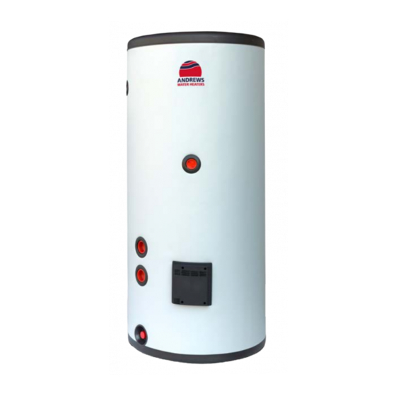
Glass Lined Buffers
10 bar, 2"-2.5"
8 bar
Important
Please read & understand all these instructions before commencing installation.
This buffer range does not incorporate an internal heat exchanger.
Please leave this manual with the customer for future reference
Andrews. Built to perform.
Advertisement
Table of Contents

Subscribe to Our Youtube Channel
Summary of Contents for andrews BUFFER-GL200-8
- Page 1 10 bar, 2”-2.5” 8 bar Important Please read & understand all these instructions before commencing installation. This buffer range does not incorporate an internal heat exchanger. Please leave this manual with the customer for future reference Andrews. Built to perform.
-
Page 2: Table Of Contents
Contents Product Specification Introduction General requirements Installation standards Storage and handling Before Installation ErP data information 8 bar Buffer dimensions 10 bar Buffer dimensions Weights Standing Heatloss Limitations Installation & Commissioning General Installation Cold Water Supply Secondary circulation and De-Stratification Discharge Pipe work Commissioning Maintenance &... -
Page 3: Product Specification
Product specification Introduction Congratulations on your purchase of an Andrews buffer vessel. The Andrews buffer products are manufactured from top quality materials and meet all the latest relevant safety and constructional standards. General Requirements IMPORTANT: Please read and understand this product guide before installing the Andrews buffer vessel. -
Page 4: Storage And Handling
Storage and Handling Please take care when handling a packaged Andrews buffer vessel. The unit is heavy and must only be moved manually within safe working practices. If the unit is to be stored before installation, it must be placed on a secure, level surface and in a dry, frost free environment. - Page 5 8 bar Glass Lined Buffers 200 & 300 Ltr...
- Page 6 500 Ltr...
- Page 7 800 & 1000 Ltr...
- Page 8 10 bar Glass Lined Buffers 300 Ltr...
- Page 9 500 Ltr...
- Page 10 800 Ltr...
- Page 11 N o m i n a l Unit Weight (kg) Capacity Empty Full (Litres) 1198 1000 Table 5: Weights N o m i n a l Per Day Per Year Capacity (kWh/24h) kWh/24h) (Litres) 1.34 1.61 2.23 2.14 2.76 1007 1000 Table 6: Standing heat-loss Testing is carried out to BS EN12897...
-
Page 12: Limitations
Limitations • The Andrews buffer vessel should not be used in any of the following instances: • Solid fuel boilers or any other boiler in which the energy input is not under effective thermostatic control unless additional and appropriate safety measures are installed. - Page 13 If a secondary circulation system is required it is recommended that it be connected to the Andrews buffer similar to Figure 9. The secondary return pipe should be in 28mm pipe and incorporate a check valve to prevent back flow, smaller pipe diameters can be used but may have a reduced flow.
- Page 14 The following extract is taken from latest G3 Regulations Discharge pipes from safety Devices Discharge pipe D1 3.50 Safety devices such as temperature relief valves or combined temperature and pres- sure relief valves (see paragraphs 3.13 or 3.18) should discharge either directly or by way of a manifold via a short length of metal pipe (D1) to a tundish.
- Page 15 Note: An alternative approach for sizing discharge pipes would be to follow Annex D, section D.2 of BS 6700:2006 + A1:2009 Specification for design, installation, testing and maintenance of services supplying water for domestic use within buildings and their curtilages. 3.59 Where a single common discharge pipe serves more than one system, it should be at least one pipe size larger than the largest individual discharge pipe (D2) to be connected.
-
Page 16: Discharge Pipe Work
Discharge Pipe work It is a requirement of Building Regulations that any discharge from an unvented system is conveyed to where it is visible, but will not cause danger to persons in or about the building. The tundish and discharge pipes should be fitted in accordance with the requirements and guidance notes of Building Regulations. - Page 17 Notes: 1) Discharge pipe-work D2 can now be a plastic pipe but only pipes that have been tested to a minimum 110°C must be used. 2) Discharge pipe D2 can now be plumbed in the soil stack but only soil stacks that can handle temperatures of 99°C or greater should be used.
-
Page 18: Commissioning
Connect up primary heat source as per manufacturers instructions. Fill up primary and secondary circuits, bleeding any air that may be trapped and check for leaks. The Andrews range of buffers do not have an internal heat ex- changer. Take care that the Primary Heat source can handle the working pressure of the cylinder. - Page 19 NEVER bypass any thermal controls or operate system without the necessary safety valves. iv) Water contained in the Andrews buffer unit may be very hot, especially following a thermal control failure. Caution must be taken when drawing water from the unit.
- Page 20 ` The Andrews water heater has not been subjected to excessive pressure beyond the guidelines detailed in the installation instructions. ` The Andrews water heater has not been subjected to frost, nor has it been tampered with or been subject to misuse or neglect.
- Page 21 Conditions of Sale which are available on request. ICOM Customer support Energy Association 8am-5pm, Monday-Friday 0345 070 1055 andrewswaterheaters.co.uk linkedin.com/company/andrews-water-heaters @AndrewsWH Andrews. Built to perform. A Baxi Heating brand Registered office address: Baxi Heating UK, Brooks House, Coventry Road, Warwick CV34 4LL...


Need help?
Do you have a question about the BUFFER-GL200-8 and is the answer not in the manual?
Questions and answers