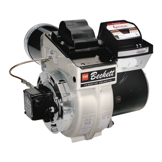
Beckett SF Series Manual

Beckett SF Series Manual

Oil burner

Advertisement

Potential for Fire, Smoke and Asphyxiation Hazards
Incorrect installation, adjustment, or misuse of this burner could result in death, severe
personal injury, or substantial property damage.
To the Homeowner or Equipment Owner:
y
Please read and carefully follow all instructions
provided in this manual regarding your
responsibilities in caring for your heating
equipment.
y
Contact a professional, qualified service agency for
installation, start-up or service work.
y
Save this manual for future reference.
To the Professional, Qualified Installer or Service Agency:
y
Please read and carefully follow all instructions provided
in this manual before installing, starting, or servicing this
burner or heating system.
y
The Installation must be made in accordance with all state
and local codes having jurisdiction.

Advertisement

Table of Contents
loading

Summary of Contents for Beckett SF Series

  • Page 1 Potential for Fire, Smoke and Asphyxiation Hazards Incorrect installation, adjustment, or misuse of this burner could result in death, severe personal injury, or substantial property damage. To the Homeowner or Equipment Owner: To the Professional, Qualified Installer or Service Agency: Please read and carefully follow all instructions Please read and carefully follow all instructions provided provided in this manual regarding your...
  • Page 2: Table Of Contents

    Combustion Air Supply ..............6 Clearances to Burner and Appliance ..........7 Combustion Chamber — Burner Retrofitting ........ 7 Your Beckett burner will provide years of Prepare the Burner ............7 efficient operation if it is professionally Burner Fuel Unit ................7 Attach Air Tube (if not already installed) ........
  • Page 3: General Information

    15 to 45 seconds (optional) 15 seconds maximum Primary Control Beckett GeniSys 7575P Beckett GeniSys 7505 or 7575 Option to ship less Primary Control (Model 7575P Primary Control with “valve-on delay” and for Pressure Washer Industry “motor-off delay” required in final installation.) Figure 1 –...
  • Page 4 Section: GENERAL INFORMATION Table 1 – Burner Specifications Frozen Plumbing and Model SM Firing rate range: 01.25 – 3.00 GPH Water Damage Hazard Capacity Input: 175,000 – 420,000 Btu/hr (Note1) If the residence is unattended in severely cold Model SF Firing rate range: 1.25 - 5.50 GPH weather, burner primary control safety lockout, Capacity...
  • Page 5: Inspect/Prepare Installation Site

    2.5-5.5 F310 None SF65FU SF90FU SF130FU SF160FU at once and file the appropriate claim. SM Burner Only When contacting Beckett for service information — 1.25-2.00 2-3/4 SM65VW SM90VW SM130VW SM160VW Please record the burner serial number (and have 2.00-3.00 F220...
  • Page 6: Inspect Chimney Or Direct Vent System

    Section: INSPECT/PREPARE INSTALLATION SITE Figure 2 – Chimney Design - Above the Roof NOTE: Correct chimney design is Minimum Clearence: 2 FT. shown by dotted lines. Incorrect chimney design, as shown by the solid lines, may result in down-drafts. Inspect Chimney or Direct Vent System Therefore, it is strongly recommended that an approved insulated stainless steel liner be installed.
  • Page 7: Clearances To Burner And Appliance

    Section: PREPARE THE BURNER Exhaust Fans and Other Air-Using Devices Install Burner Nozzle (if not already installed) Size air openings large enough to allow for all air- using devices in addition to the minimum area required Correct Nozzle and Flow for combustion air.
  • Page 8: Check/Adjust Electrodes

    Mounting Dimensions Servicing Nozzle Line Assembly 1. When using the Beckett universal adjustable flange, 1. Turn off power to burner before proceeding. mount the air tube at a 2° downward pitch unless 2. Disconnect oil connector tube from nozzle line.
  • Page 9 4” through 4- “, 2- for dimension A greater than 4- ”. 13/32” measure the distance to the face of the head. A Beckett T501 or T650 gauge may also be used. Note 2: When using a straight edge. SF/SM Burner Manual...
  • Page 10: Installing The Oil Tank And Supply System

    Section: MOUNT BURNER ON APPLIANCE Figure 5 – Mounting Burner in Appliance Figure 6 – Inside Tank Gravity Feed System If space between burner air tube and opening exceeds 1/2 inch, pack burner opening with ceramic fiber refractory. 1/4” 4” 7/8”...
  • Page 11: Wire Burner

    Section: WIRE BURNER Wire Burner Fuel supply below the level of the burner – When the fuel supply is more than eight feet below the level of the burner, a two-pipe fuel supply system Burner Packaged with Appliance is required. Depending on the fuel line diameter and horizontal and vertical length, the installation may also require a two-stage pump.
  • Page 12: Burner Controls

    Section: BURNER CONTROLS Burner Controls Wiring Explosion, Fire, Scald, SM burners shipped less Primary Control from RWB and Burn Hazard shall require Model 7575P Primary Control be installed with valve-on delay and motor-off delay to meet CSA All heating appliances must have HIGH B140.0 per wiring in Figure 9B.
  • Page 13 Section: BURNER CONTROLS Figure 8B – 7575 Control (all connections are located on the bottom of the control.) Reset Button with Red Light Wiring Connections Yellow Light Green Light Thermostat Communication Terminals Port Cad Cell Connections Figure 8C – Optional Components: Contractor’s Tool: Hand-held device Alarm Module: For adding isolated low voltage for programming and diagnostics...
  • Page 14 Section: BURNER CONTROLS Typical Burner Sequence of Operation for GeniSys 7505 and 7575 Controls. Refer to the appliance manufacturer’s wiring diagram for actual specifications. Pump Standby prime Trial for Lockout Valve-on delay ignition Ignition carryover Recycle Motor-off delay 1. Standby: The burner is idle, waiting for a call for 5.
  • Page 15: Reset Button Operation

    Section: BURNER CONTROLS Figure 9a – Interrupted ignition, valve-on delay only Figure 9b – Interrupted ignition, valve-on delay and (no motor-off delay) – for SF Burners only. motor-off delay – for SF and SM Burners. SAFETY AND SAFETY AND OPERATING OPERATING LIMITS LIMITS...
  • Page 16: Wire Burner

    Quick Reference Guide, part number 61666 for improperly, it may require an isolation relay for proper special pump priming sequence. operation. The Beckett A/C Ready Kit (part no. 51950U) ○ Prepare for combustion tests by drilling a ¼” provides this function. Wiring instructions are included with sampling hole in the flue pipe between the the A/C Ready Kit.
  • Page 17: Startup / Checkout

    Section: START UP BURNER/SET COMBUSTION ○ To reset, hold the button down for 15 seconds until 2. After flame is established and the burner igniter turns the red light turns off and the yellow light turns on. off, close the hand valve in the oil supply line. 3.
  • Page 18: Perform Regular Maintenance

    Section: START UP BURNER/SET COMBUSTION □ ─ If the draft level has changed, recheck If motor is not permanently lubricated, oil motor with a few drops of SAE 20 nondetergent oil at each oil hole. the smoke and CO levels and readjust DO NOT over oil motor.
  • Page 19: Replacement Parts

    Splined Nut 2184404U CleanCut 2182602U Blocking Oil Solenoid Valve 2460 Single-Stage ‘A’ 5685 Base Pedestal Kit 2256 Pump outlet fitting (not shown) ** Contact your Beckett Representative for part number and pricing. Pump holding screws (not shown) SF/SM Burner Manual...
  • Page 20: Limited Warranty Information

    The R. W. BECKETT CORPORATION (“Beckett”) warrants to persons who purchase its “Products” from Beckett for resale, or for incorporation into a product for resale (“Customers”), that its equipment is free from defects in material and workmanship. To qualify for warranty benefits, products must be installed by a qualified service agency in full compliance with all codes and authorities having jurisdiction, and used within the tolerances of Beckett’s defined product specifications.

Table of Contents