Table of Contents
Advertisement
Quick Links
Advertisement
Table of Contents
Troubleshooting

Related Manuals for Kollmorgen MMC Smart Drive Series


Summary of Contents for Kollmorgen MMC Smart Drive Series
- Page 1 © Smart Drive and Digital MMC Control Hardware Manual Version 6.3 Catalog No. M.1301.5524 Part No. M.3000.1430 IND. CONT. EQ. 12KP Keep all product manuals as a product component during the life span of the product. Pass all product manuals to future users/owners of the product.
- Page 3 All rights reserved. No part of this work may be reproduced in any form (by printing, photocopying, microfilm or any other method) or processed, copied or distributed by electronic means without the written permission of Kollmorgen. Kollmorgen - June 2014...
- Page 4 The text and illustrations are not binding in detail. Kollmorgen shall not be liable for any technical or editorial omissions occurring in this document, nor for any consequential or incidental damages resulting from the use of this document.
-
Page 5: Table Of Contents
1.2 Contents of This Manual......................9 1.3 Software and Manuals......................9 1.3.1 Required Software and Manuals..................9 1.3.2 Suggested Manuals ......................9 1.4 Kollmorgen Support Contact ....................11 2 Safety Precautions......................... 13 2.1 System Safety ........................13 2.1.1 User Responsibility ....................... 13 2.1.2 Safety Instructions...................... - Page 6 6 460V 3 Phase MMC Smart Drive NextGen ................. 121 6.1 Control Section Connectors, Switches, LEDs ..............124 6.1.1 Status Display......................124 6.1.2 Node Address Rotary Switches.................. 124 6.1.3 Digital Link Ports......................125 6.1.4 Feedback Connectors (F1 & F2) ................127 Kollmorgen - June 2014...
- Page 7 8.2.1.4 24V Power Connector (J1) ................226 8.2.1.5 Motor Brake Connector (X101) .................227 8.2.2 Size 2 Power Section Connectors................227 8.2.2.1 AC Power Connector ..................229 8.2.2.2 Motor Connector ....................230 8.2.2.3 24V Power Connector (J1) ................231 8.2.3 Size 3 Power Section Connectors................232 Kollmorgen - June 2014...
- Page 8 10.3 AKM/DDR Motor Power Cables ..................308 10.4 LSM/MSM Motor Connector Kits ..................309 10.5 LSM/MSM Motor Power Cables..................310 10.6 LSM/MSM Motor Fan Cables..................... 313 11 Maintenance and Troubleshooting ..................315 11.1 Maintenance ........................315 Kollmorgen - June 2014...
- Page 9 A 460V MMC Smart Drive DC Bus Sharing ...................371 A.1 Introduction ..........................371 A.2 DC Bus Sharing with AC Power to All Drives...............371 A.3 DC Bus Sharing with AC Power to One Drive..............373 Index..............................377 Sales and Service..........................383 Kollmorgen - June 2014...
- Page 10 MMC Smart Drive Hardware Manual TABLE OF CONTENTS Kollmorgen - June 2014...
-
Page 11: Introduction To The Mmc Smart Drive
• Procedures for mounting, wiring, and connecting the MMC Smart Drive and stan- dard Kollmorgen motors recommended for use with the MMC Smart Drive. • Recommended drive system wiring guidelines for signal separation and differen- tial devices. - Page 12 MMC Smart Drive Hardware Manual INTRODUCTION TO THE MMC SMART DRIVE • Ethernet Application Specific Function Block Manual General Purpose Application Specific Function Block • Manual Kollmorgen - June 2014...
-
Page 13: Kollmorgen Support Contact
MMC Smart Drive Hardware Manual INTRODUCTION TO THE MMC SMART DRIVE Kollmorgen Support Contact Contact your local Kollmorgen representative for: • Sales and order support • Product technical training • Warranty support • Support service agreements Kollmorgen Technical Support can be reached: In the United States, telephone (800) 558-4808 •... - Page 14 MMC Smart Drive Hardware Manual INTRODUCTION TO THE MMC SMART DRIVE Kollmorgen - June 2014...
-
Page 15: Safety Precautions
Only qualified personnel should operate the equipment. • Never perform service or maintenance while automatic control sequences are in operation. To avoid shock or serious injury, only qualified personnel should perform mainte- • nance on the system. Kollmorgen - June 2014... -
Page 16: Safety Signs
The type of warning is given by the pictorial representation on the sign plus text if used. To ignore such a caution could lead to severe injury or death arising from an unsafe practice. Kollmorgen - June 2014... -
Page 17: Safety First
These notices provide information intended to prevent potential pe sonal injury. Safety First Kollmorgen equipment is designed and manufactured with consideration and care to generally accepted safety standards. However, the proper and safe performance of the equipment depends upon the use of sound and prudent operating, maintenance and servicing procedures by trained personnel under adequate supervision. -
Page 18: Operating Safely
This practice assures a cautious approach which may prevent accident or injury. • To remove power: LOCK THE SUPPLY CIRCUIT DISCONNECTING MEANS IN THE OPEN POSI- TION. APPLY LOCKOUT/TAGOUT DEVICES IN ACCORDANCE WITH A DOCU- MENTED AND ESTABLISHED POLICY. Kollmorgen - June 2014... -
Page 19: Safe Cleaning Practices
Do not use toxic or flammable solvents to clean control system hardware. • • Turn off electrical power (lock out) before cleaning control system assemblies. • Keep electrical panel covers closed and power off when cleaning an enclosure. Kollmorgen - June 2014... - Page 20 Never use water to clean control equipment unless you are certain that the equip- • ment has been certified as sealed against water ingress. Water is a very good conductor of electricity and the single largest cause of death by electrocution. Kollmorgen - June 2014...
-
Page 21: Installing The Mmc Smart Drive
If you find damage, either concealed or visible, contact your buyer to make a claim with the shipper. If degraded performance is detected when testing the unit, contact your distributor or Kollmorgen. Do this as soon as possible after receipt of the unit. Kollmorgen - June 2014... -
Page 22: Complying With European Directives
Chapters 5 and 6 for applicable directives. Servo amplifiers are considered to be subsystems when incorporated into electrical plants and machines for industrial use. The Kollmorgen servo amplifiers have been designed and tested as such. They bear the CE mark and are provided with a Declaration of Conformance. -
Page 23: Controlling Heat Within The System
MMC Smart Drive. • Put them in another control cabinet above or to one side of the cabinet with the MMC Smart Drive. This protects the MMC Smart Drive from both heat and electri- cal noise. Kollmorgen - June 2014... -
Page 24: Bonding
6. Attach the subpanel to the subpanel stud by sliding a star washer and then a flat washer over the stud. Turn and tighten a nut onto the stud. Kollmorgen - June 2014... -
Page 25: Bonding A Ground Bus Or Chassis Using A Bolt
3.9.5 Bonding Multiple Subpanels Kollmorgen recommends bonding both the top and bottom of subpanels sharing the same enclosure. Use a 25.4 mm (1.0 in.) x 6.35 mm (0.25) wire braid. Be sure the area around each wire braid fastener is clear of any non-conductive materials. Bond the cabinet ground bus to at least one of the subpanels. -
Page 26: Drive System Grounding Procedures
Devices to be connected directly to the Single Point Ground include: • Plant safety ground. • Protective earth ground(s) from the MMC Smart Drive power terminals. • The metal panel or cabinet on which the MMC Smart Drive is mounted. Kollmorgen - June 2014... - Page 27 Also, you must ensure that the MMC Smart Drive “Protective Earth Ground” connection is connected to SPG, and that the MMC Smart Drive is mounted to a metal panel or enclosure that is connected to SPG. Kollmorgen - June 2014...
- Page 28 Mount the filter as close to the Drive as possible. If the distance exceeds 600 mm • (2.0 ft), use shielded cable between the Drive and the filter, strapping the shield to chassis at each end of the cable. This is particularly important for attenuation of higher frequency emissions (5-30 MHz). Kollmorgen - June 2014...
-
Page 29: Grounding Multiple Drives In The Same Cabinet
3.12 System Wiring Guidelines The MMC Smart Drive relies on electrical signals to report what is going on in the application and to send commands to it. In addition, signals are constantly being Kollmorgen - June 2014... -
Page 30: Recommended Signal Separation
Inside a control cabinet, connect the shields of shielded cables at the MMC Smart Drive. It is recommended that factory cables (from Kollmorgen) are used between MMC drives, controls, and motors to ensure CE compliance. - Page 31 To prevent excessive conducted emissions from a DC power source (typically 24V) used for digital I/O, a .001 micro farad capacitor should be used. Connect the capacitor from the +24V DC to COMMON at the distribution terminals. Kollmorgen - June 2014...
-
Page 32: Building Your Own Cables
Use a twisted pair cable whenever possible, twisting differential signals with each • other, and single-ended signals with the appropriate ground return. NOTE Kollmorgen cables are designed to minimize EMI and are recommended over hand-built cables. 3.12.3 Routing Cables Guidelines for routing cables in a cabinet include the following: •... -
Page 33: System Ac Power Wiring Guidelines
Refer to the Specifications sections in Chapter 4 of this manual for device and • conductor requirements. • Clamp the motor power cable shield to the drive using the Kollmorgen supplied bracket. Maximum tightening torque for bracket screws is 10 lb-in. Kollmorgen - June 2014... -
Page 34: Connecting Interface Cables
Ensure motor power connectors are used for connection pur- poses only. Do not use them to turn the unit on and off. • To avoid personal injury and/or equipment damage, ensure shielded power cables are grounded to prevent potentially high voltages on the shield. Kollmorgen - June 2014... -
Page 35: Preparing Motor Connection Wires
Preparing Motor Connection Wires NOTE It is recommended that Kollmorgen cables be used. Kollmorgen cables are designed to minimize EMI and are recommended over hand-built cables. 1. Strip back cable jacket approximately 152 mm (6.0 in.) from the end of the cable. - Page 36 Figure 3-4: Terminating Motor Power Cable for 230V Drive Shield CAUTION - Risk of Electric Shock High Voltage may exist up to 10 minutes after removing power Motor Cable Jacket Clamp Clamp Clamp Screw Screw Motor Cable Kollmorgen - June 2014...
- Page 37 Clamp Screw Shield Clamped to Mounting Panel Clamp Screw Maximum 10 cm from Cable Jacket the Edge of the Drive MMC-SD 460 DRIVE Shield Clamp Shield Clamped to Bottom of Drive Cable Jacket Clamp Screw TO MOTOR Kollmorgen - June 2014...
- Page 38 MMC Smart Drive Hardware Manual INSTALLING THE MMC SMART DRIVE Figure 3-6: Terminating Power Cables for 460V SDN Drive Drive Shield Bracket Cable Clamp Cable Note: Shield Bracket, Cable Clamp(s), Cable(s) are installed by User Kollmorgen - June 2014...
-
Page 39: System Power Devices
The MMC Smart Drive is powered from an external AC power source. The power required for each 230V drive type is listed in Table 4-1. The power required for each 460V drive type is listed in Table 4-2. Kollmorgen - June 2014... - Page 40 Smart Drive (SD) Drive Model pertains to Analog (no dash suffix) and digital (-D & -DN) b. Transformer sizes shown are worse-case. For a more accurate determination of transformer size, see section 4.4 on page 59 for calculating application trans- former requirement. c. Consult Factory Kollmorgen - June 2014...
- Page 41 Smart Drive (SD) Model pertains to Analog (no dash suffix) and digital (-D & -DN) b. Transformer sizes shown are worse-case. For a more accurate determination of transformer size, see section 4.4 on page 59 for calculating application trans- former requirement. c. Consult Factory Kollmorgen - June 2014...
-
Page 42: Protection
The temperature-sensing device must be properly connected to the drive, as • described in the MMC Smart Drive Hardware Manual that can be found at www.glcontrols.com. • The temperature-sensing device must be properly configured in PiCPro (as described in the PiCPro Manual and/or PiCPro on-line Help) Kollmorgen - June 2014... -
Page 43: 24Vdc Input Power Protection (460V Sd Only)
5,000 RMS symetrical short circuit amperes (250V maximum), the fuse type provided for Protection has no “Clearing I t” restrictions, and must meet the following requirements: have a current rating no greater than the “Maximum Fuse Size” in Table 4-3 • Kollmorgen - June 2014... - Page 44 (Bussmann Fuse P/N) S200-DLS Drive Model = 120VAC = 240VAC = 240VAC 1 Phase 1 Phase 3 Phase S20260-DLS (LPJ-5SP) (LPJ-5SP) (LPJ-5SP) S20360-DLS (LPJ-10SP) (LPJ-10SP) (LPJ-8SP) S20660-DLS (LPJ-20SP) (LPJ-20SP) (LPJ-15SP) S21260-DLS (JKS-30) (JKS-30) S22460-DLS (JKS-30) (JKS-30) Kollmorgen - June 2014...
-
Page 45: Smart Drive (Sd) Protection Requirements
Over Current Protection Device in the case of a sustained Over Current condition. Over Current Protection must be provided in accordance with NFPA 79 7.2.3 and 7.2.10. Supplemental UL1007 protectors shall not be used to provide Branch Cir- cuit Protection. Kollmorgen - June 2014... - Page 46 • In order to meet UL requirements for the 230V Smart Drive, the over-current protection device (fuses) must be UL-Listed Class RK1, J, or CC • Model MMC-SD-3.0-230 must be used with 30 Amp fuses or smaller Kollmorgen - June 2014...
-
Page 47: Smart Drive (Sd & Sdn) Protection Requirements
Although these drives provide solid state motor overload protection at 125% of the rated FLA Current and short circuit protection, this Integral solid state short circuit protection does not provide branch circuit protection. Branch circuit protection must be Kollmorgen - June 2014... - Page 48 Short Circuit Protection and Over Current Protection, and may be used on Branch Circuits that supply up to 100,000 RMS symetrical short circuit amperes (480V maximum). Use two fuses connected in series, that, in combination, meet all of the require- • ments: Kollmorgen - June 2014...
- Page 49 UL REQUIREMENTS In order to meet UL requirements, UL-Listed High Speed Class J (HSJ) semi- conductor fuses (like those listed in Table 4-5) must be used for Branch cir- cuit Protection of the 460V Smart Drive. Kollmorgen - June 2014...
- Page 50 This is the maximum “Clearing I t Rating” of a fuse used for Device Protection. Use a fuse that falls in the operating point below the stated release integral (I t). All of the listed “Combination Fuses” meet this requirement. Kollmorgen - June 2014...
- Page 51 This is the maximum fuse size that can be used for Device and Branch Circuit Protection. Kollmor- gen recommends the use of HSJ or DFJ fuses only. d. Kollmorgen part numbers for these fuses can be found in Table 4-6 on page 50 e.
- Page 52 M.1016.0614 DFJ125 M.3000.0202 200 Amp M.1016.0614 DFJ150 M.3000.0203 200 Amp M.1016.0614 DFJ175 M.3000.0204 200 Amp M.1016.0614 DFJ200 M.3000.1661 200 Amp M.1016.0614 DFJ225 M.3000.1662 400 Amp M.3000.1665 DFJ300 M.3000.1663 400 Amp M.3000.1665 DFJ350 M.3000.1664 400 Amp M.3000.1665 Kollmorgen - June 2014...
-
Page 53: Line Reactors
Line reactors are not necessary for the 230V MMC Smart Drives or the 460V size 1 and 2 MMC Smart Drives. Line reactors are required for the 460V size 3 and size 4 MMC Smart Drives. Kollmorgen - June 2014... -
Page 54: Specifications And Dimensions For Required Line Reactors
Part Inductance Weight Amperage Loss Number 1.2 mH 14 lbs. M.1302.7373 0.38 x 0.75 3.00 (4 SLOTS) 3.43 2.35 LABEL WIRE RANGE: 22-5 AWG CAUTION - TERMINAL SCREW TIGHTENING TORQUE: 16 in-lb MAX 6.00 7.25 MAX Kollmorgen - June 2014... - Page 55 Part Inductance Weight Amperage Loss Number 0.8 mH 16 lbs. M.1302.7374 0.38 x 0.75 3.00 (4 SLOTS) 4.00 WIRE RANGE: 22-5 AWG LABEL 2.63 CAUTION - TERMINAL SCREW TIGHTENING TORQUE: 16 in-lb MAX 5.75 7.25 MAX Kollmorgen - June 2014...
- Page 56 Part Inductance Weight Amperage Loss Number 0.7 mH 28 lbs. M.1302.7375 0.38 x 0.75 3.00 (4 SLOTS) 4.75 LABEL 3.16 WIRE RANGE: 18-4 AWG CAUTION - TERMINAL SCREW TIGHTENING TORQUE: 16 in-lb MAX 7.35 9.00 MAX Kollmorgen - June 2014...
- Page 57 MMC Smart Drive Hardware Manual SYSTEM POWER DEVICES Table 4-10: MMC-SD-30-460 Line Reactor Specifications Fundamental Power Part Inductance Weight Amperage Loss Number 0.5 mH 27 lbs. M.3000.0105 Kollmorgen - June 2014...
- Page 58 MMC Smart Drive Hardware Manual SYSTEM POWER DEVICES Table 4-11: MMC-SD-42-460 Line Reactor Specifications Fundamental Power Part Inductance Weight Amperage Loss Number 0.4 mH 51 lbs. M.3000.0106 Kollmorgen - June 2014...
- Page 59 MMC Smart Drive Hardware Manual SYSTEM POWER DEVICES Table 4-12: MMC-SD-51-460 Line Reactor Specifications Fundamental Power Part Inductance Weight Amperage Loss Number 100A 0.3 mH 51 lbs. M.3000.0107 Kollmorgen - June 2014...
- Page 60 MMC Smart Drive Hardware Manual SYSTEM POWER DEVICES Table 4-13: MMC-SD-65-460 Line Reactor Specifications Fundamental Power Part Inductance Weight Amperage Loss Number 130A 180W 0.2 mH 57 lbs. M.3000.0108 Kollmorgen - June 2014...
-
Page 61: Isolation Transformers
Calculations are multiplied by a factor to compensate for the power and loss elements within a power system. A factor of 2.0 is used with a single phase system and a factor Kollmorgen - June 2014... -
Page 62: External Shunts
This section describes how to select the proper External Shunt based on system parameters. Kollmorgen recommends you use the Motion Solutions Sizing Software to determine the need for and type of external shunt. However, you may perform the following calculations to choose the external shunt for your application. - Page 63 5. Determine the Continuous Shunt Power that would be delivered to the shunt resistor for this application: Duty Cycle of Peak or Peak x Decel Time) (Total Cycle Time) = Continuous • Shunt Power in Watts 6. Choose an external shunt from Table 4-15. Kollmorgen - June 2014...
-
Page 64: Mounting External Shunts
SDN drives a. Drive Model pertains to Analog (no dash suffix) and digital (-D) 4.5.2 Mounting External Shunts This section describes the mounting requirements for External Shunts available from Kollmorgen. Kollmorgen - June 2014... - Page 65 MMC Smart Drive Hardware Manual SYSTEM POWER DEVICES EXTERNAL SHUNTS ON SMART DRIVE NEXTGEN (SDN) DRIVES For a detailed description of these shunts, refer to the Kollmorgen “AKD/S700 Accessories Manual” which can be found at www.kollmorgen.com. Kollmorgen - June 2014...
- Page 66 MMC Smart Drive Hardware Manual SYSTEM POWER DEVICES Figure 4-2: Mounting Dimensions for 230V Active Shunt Kit (P/N M.3000.1346) Kollmorgen - June 2014...
- Page 67 3.66 in. (93 mm) 27.76 in. (705 mm) Figure 4-5: Mounting Dimensions for 460V External Shunt (P/N M.1302.7060) 20.71 in. (526 mm) 5.90 in. (150 mm) 0 5, 5 x 8 23.82 in. (605 mm) 7.28 in. (185 mm) Kollmorgen - June 2014...
- Page 68 19.80 in. (503 mm) 13.38 in. (340 mm) 20.70 in. (526 mm) 11.81 in. (300 mm) 21.65 in. (550 mm) 5.91 in. (150 mm) 5.91 in. (150 mm) 0 5, 5 x 16.93 in. (430 mm) Kollmorgen - June 2014...
- Page 69 19.80 in. (503 mm) 13.38 in. (340 mm) 20.70 in. (526 mm) 11.81 in. (300 mm) 21.65 in. (550 mm) 5.91 in. (150 mm) 5.91 in. (150 mm) 0 5, 5 x 8 16.93 in. (430 mm) Kollmorgen - June 2014...
- Page 70 MMC Smart Drive Hardware Manual SYSTEM POWER DEVICES Figure 4-8: Mounting Dimensions for Reduced Size Panel mount Shunts Kollmorgen - June 2014...
-
Page 71: Connecting Shunt Modules
Active Shunt Module to this drive. The 230V, 3-Phase MMC Smart Drive requires the use of a Passive Shunt module (regen resistor). Refer to Figure 4-10 for wiring an Passive Shunt Module to this drive. Kollmorgen - June 2014... - Page 72 SYSTEM POWER DEVICES Figure 4-9: 230V, 1-Phase MMC Smart Drive Shunt Wiring CENTURION DSM MMC SMART DRIVE DYNAMIC BRAKE MODULE CENTURION DSA DC BUS BRAKING DC + DYNAMIC BRAKE RESISTOR DC - RES. + RES. - Kollmorgen - June 2014...
-
Page 73: 3-Phase Mmc Smart Drive (-Sd) Shunt Wiring
Figure 4-11: 460V, 3-Phase MMC Smart Drive (-SD) Shunt Wiring Shunt Module Using twisted pair wire, Connect Ba+ to + Terminal on Shunt Module, Connect Ba- to - Terminal on Shunt Module 460V MMC Smart Drive Shunt/DC Bus Terminal Strip Kollmorgen - June 2014... -
Page 74: Line Filters
The coupling mechanism can be radiation, or stray capacitance between the wires. Figure 4-12: Block Diagram Simplified for 3-Phase Line Filter Kollmorgen - June 2014... - Page 75 The best way to ensure this is to use unpainted zinc-coated mounting plates. Table 4-16: Part Numbers for AC Line Filters Part Current For Drive Number Single Phase Versions of: 6A, 250V, 1 Phase M.1015.6922 MMC-SD-0.5-230 MMC-SD-1.0-230 Kollmorgen - June 2014...
- Page 76 16A, 480V, 3 Phase MMC-SD-6.0-460 M.1302.5244 MMC-SD-8.0-460 MMC-SD-12.0-460 30A, 480V, 3 Phase M.1302.5245 MMC-SD-16.0-460 42A, 480V, 3 Phase MMC-SD-24.0-460 M.1302.5246 MMC-SD-30.0-460 56A, 480V, 3 Phase M.1302.5247 MMC-SD-42.0-460 75A, 480V, 3 Phase MMC-SD-51.0-460 M.1302.5248 100A, 480V, 3 Phase MMC-SD-65.0-460 M.3000.0109 Kollmorgen - June 2014...
- Page 77 1.6Kg (2.5 Lb) 4 x M4 4 x M4 4 x M4 Back Mounting 2 x M5 2 x M6 2 x M6 Side Mounting a. Line filters are manufactured to millimeter dimensions (inches are approximate con- versions). Kollmorgen - June 2014...
- Page 78 Range T Power Loss (typical) Site Altitude Below 2000 m above sea level (higher altitudes on request) Storage Tem- perature -25°C ... +85°C Range Type of Protec- IP20 tion Weight 0.6kg 1.0kg 1.3kg 1.6kg 1.9kg 2.6kg 4.0kg Kollmorgen - June 2014...
-
Page 79: Dimensions For 230V Line Filters
MMC Smart Drive Hardware Manual SYSTEM POWER DEVICES 4.6.2 Dimensions for 230V Line Filters NOT E: S pring clips replace T erminal screws on 6 Amp Filter (P/N 401-30222-00) SINGLE PHASE SINGLE PHASE SINGLE PHASE M.1015.6922 M.1015.6917 M.1015.6918 MEASUREMENT Kollmorgen - June 2014... -
Page 80: Dimensions For 460V Line Filters
MMC Smart Drive Hardware Manual SYSTEM POWER DEVICES 4.6.3 Dimensions for 460V Line Filters Part Number M.1302.5241 M.1302.5244 M.1302.5245 M.1302.5246 M.1302.5247 M.1302.5248 M.3000.0190 Kollmorgen - June 2014... -
Page 81: Phase Mmc Smart Drive Nextgen
Brake Output (this can also be used as a General Purpose Output) • Supports DC bus sharing • Safe Torque Off capability The Drive’s Control Section features the following: Connects to Kollmorgen’s Digital Link bus • Two-digit error/status display • A primary feedback connector (F1), containing the following features: •... - Page 82 230V 3 PHASE MMC SMART DRIVE NEXTGEN • Six General Purpose DC Inputs (sink or source in group of six) Two General Purpose DC Outputs (sourcing) • Analog Input • Analog Output • Relay Output • Kollmorgen - June 2014...
- Page 83 Risk of Electrical Shock combined into one High voltage may exist up to 5 connector on the minutes after removing power 3A, 6A, and 12A Drives Grounding Block not present on 3A, 6A, and 12A Drives Kollmorgen - June 2014...
-
Page 84: Control Section Connectors, Switches, Leds
As an example, rotating S1 to a setting of 2 equals the value of 20 (2 x 10). Rotating S2 to a setting of 5 equals the value of 5. The actual address setting is 25 (20 + 5). (10s) (1s) Kollmorgen - June 2014... -
Page 85: Digital Link Ports
Transmits data to con- Transmit Data + nected drives. Transmits data to con- Transmit Data - nected drives. Provides a path for the Protective Connector ground signal to an exter- Connector Shell Ground Shell nal single point ground. Kollmorgen - June 2014... - Page 86 OUT Connector “OUT” Transmit + LINK Transmit - Receive + Not Used Not Used Receive - Not Used Not Used Provides a path for the Connector ground signal to an ex- Shield ternal single point ground. Kollmorgen - June 2014...
-
Page 87: Feedback Connectors (F1 & F2)
Available Breakout Boxes and Cables are described in Table 5-10. • Breakout Box dimensions are shown in Figure 5-2 • Breakout Board dimensions are shown in Figure 5-3 • Feedback Port to Motor Cables are described in section 5.1.4.2 on page 95 • Kollmorgen - June 2014... - Page 88 PROVIDING 8VDC ENCODER POWER Some Encoders, specifically the Stegmann Hiperface, require 8VDC power to operate. 8VDC Power can be provided on pins 10 and 11 by connecting the +5V Sense Lines (pins 4 & 5) together. Kollmorgen - June 2014...
- Page 89 Pins 6 and 7 are In/Out for Hiperface, Endat, and SFD; Inputs for Digital Incremental and BiSS; and Out- puts for Resolver g. Temperature inputs (pins 8 and 9) are shared with the F2 connector h. Hiperface requires +8Vdc. To supply +8V from pin 10, connect +5V Sense lines (pins 4 & 5) together. Kollmorgen - June 2014...
- Page 90 These inputs are shared with F1. +5V Encod- Regulated +5VDC for powering er Power +5V Source the attached encoder (200ma Output max). Signal and Return path for feedback sig- Power Com- Common nals and +5V power output Kollmorgen - June 2014...
- Page 91 F2 is configured for Emulated Encoder Output, and an Input/Output when F2 is configured for SFD. c. This pin is an Input when F2 is configured for Encoder Input, and an Output when F2 is configured for Emulated Encoder Output. Kollmorgen - June 2014...
-
Page 92: Feedback Connectors (F1 And F2) Details
To accept SFD feedback device signals • Hall sensor inputs are only available on the F2 connector • Refer to Table 5-8 for more information regarding the valid combinations of feed- back on the F1 and F2 connectors. Kollmorgen - June 2014... - Page 93 • Endat 2.1 (single or multi-turn) • • Stegmann Hiperface (single or multi- turn) • BiSS (single or multi-turn) a. The F2 connector can support an Encoder input or Emulated F1 Encoder Output, but not both Kollmorgen - June 2014...
- Page 94 Green Twisted Sine/, Sin- White/Green Pair Cos, Cos+ Orange Twisted Cos/, Cos- White/Orange Pair Shell Shield a. Hall signals S1, S2, and S3 are only available on F2 b. Pins 10 & 11 are 16 AWG Kollmorgen - June 2014...
- Page 95 Figure 5-2 on page 94) is DIN-rail mounted, and provides screw terminal wire termination. Use one of the cables listed in the table to con- nect between the F1 and/or F2 connector and the Breakout Box. Kollmorgen - June 2014...
- Page 96 MMC Smart Drive Hardware Manual 230V 3 PHASE MMC SMART DRIVE NEXTGEN Figure 5-2: Feedback Port (F1 and F2) Breakout Box Dimensions Figure 5-3: Feedback Port (F1 and F2) Breakout Board Dimensions Kollmorgen - June 2014...
-
Page 97: Feedback Port (F1/F2) To Motor Cables
5.1.4.2 Feedback Port (F1/F2) to Motor Cables Cables are available that allow easy connection between the F1 & F2 Feedback Ports and various Kollmorgen motors. These cables are outlined in Table 5-11. The wiring diagram for each cable is located in the indicated Table. For information on Non-Flex versus Hi-Flex cables, refer to section 10.1 on page... - Page 98 Inner Braid Outer Braid Shell Shield Shell Shield 11-14 a. Only applicable to F2 connector b. There are two wires in pin10 c. There are two wires in pin 7 d. This wire is 22 AWG Kollmorgen - June 2014...
- Page 99 White/Grey Outer Braid Shell Shield Shell Shield 6,10,12,16,17 a. This wire is 22 AWG b. There are two wires in pin 4 c. There are two wires in pin 2 d. This wire is 16 AWG Kollmorgen - June 2014...
- Page 100 Wire Color Signal Type Signal Type Number Number Yellow Sin+ Sin+ White/Yellow Sin- Sin- Blue White/Blue Cos- Cos- Black Carrier+ Carrier+ White/Black Carrier- Carrier- Temperature+ Temperature+ White/Red Temperature- Temperature- Outer Braid Shell Shield Shell Shield 1,10-12 1-5,10,11 Kollmorgen - June 2014...
- Page 101 +5V Source +5V Source Common Common Drain Com- Com- Green Com+ Com+ White Inner Braid Shield Outer Braid Shell Shield Shell Shield 6-12 1-5,12-15 a. This wire is 22 AWG b. This wire is 24 AWG Kollmorgen - June 2014...
-
Page 102: Drive I/O Connectors (Io1 & Io2)
General Purpose Inputs, and two General Purpose Outputs (wiring example shown in See Figure 5-4 on page 103). • Pin descriptions are provided in Table 5-16 • Pin assignments are provided in Table 5-17 Kollmorgen - June 2014... - Page 103 Sourcing 7, 8, 9 able Inputs This pin determines whether the General Purpose General Purpose In- Inputs are sourcing (this pin connected to 24 Vdc) puts Sink/Source or sinking (this pin connected to 24 Vdc Common) Kollmorgen - June 2014...
- Page 104 Input 1 Return GPIN2 Input 2 GPOUT1 Output 1 GPIN3 Input 3 GPOUT2 Output 2 GPOUT GPIN4 Input 4 24VDC GPOUT GPIN5 Input 5 24VDC Re- turn GPIN6 Input 6 Relay Output 3 GPIN Sink/ Source Kollmorgen - June 2014...
- Page 105 Sourcing-type Device RELAY IO1-9 Power From Drive Source IO1-10 RELAY Load Analog IO1-3 Analog Out From Drive Input IO1-4 Analog Out Ret Device Analog In + IO1-2 External Drive Source Analog In - IO1-1 Drive Kollmorgen - June 2014...
-
Page 106: Power Section Connectors
3. The application controls the motor as desired 4. The drive is disabled via the Application Program 5. The external user-supplied circuit removes 24Vdc from the "EN" input 6. The process is repeated starting with step 1 above as required Kollmorgen - June 2014... -
Page 107: Ac Power Connector
If single-phase power is used, L1 must be connected to “hot”, and L2 must be connected to “neutral”. L3 must remain unconnected. 5.2.2.1 Line Fusing section 4.2 on page 40 for additional information on Drive Protection. Kollmorgen - June 2014... -
Page 108: Motor/Brake Connector
(Output3), but is typically defined as the Motor Brake Control. NOTE Use of a diode (as shown) or an external RC type snubber is highly recom- mended for use with inductive loads, especially DC inductive loads. Kollmorgen - June 2014... - Page 109 MMC Smart Drive Hardware Manual 230V 3 PHASE MMC SMART DRIVE NEXTGEN Figure 5-5: BR+ and BR- Wiring Examples Using External Power Source Drive Brake Control +24VDC Brake 1N4004 +24V COM Kollmorgen - June 2014...
-
Page 110: Motor/Brake Cables
Kollmorgen AKM/DDR motors. These cables are outlined in Table 5- 21. For a detailed description of these cables, refer to the Kollmorgen “AKD/S700 Accessories Manual” which can be found at www.kollmorgen.com. For information on Non-Flex versus Hi-Flex cables, refer to section 10.1 on page... -
Page 111: Dc Bus/Regen Connector
AC Power/Regen Connector, with +RBi on top, followed by -RB, -DC, and +RB. ADDITIONAL SHUNT RESISTOR INFORMATION Refer to section 4.5 on page 60 for instructions on choosing, mounting, and connecting Shunt Resistors available from Kollmorgen. Table 5-23: Pin Assignment Bus/Regen Connector Terminal Label Signal Description In/Out... -
Page 112: External Regen Resistors
12A and 24A Drives which contain internal regen resistors). Available external regen resistors are outlined in Table 5-24. For a detailed description of these resistors, including mounting information, refer to the Kollmorgen “AKD/S700 Accessories Manual” which can be found at www.kollmorgen.com. Table 5-24: External Regen Resistors Part... -
Page 113: Specifications - 230V Mmc Smart Drive Nextgen
Pollution Pollution level 2 per IEC 60644-1 Vibration Limits (per IEC 68-2-6) 10-57 Hz (constant amplitude.15 mm) Operating/Non-operating 57 - 2000 Hz (acceleration 2 g) Shock (per IEC 68-2-27) Four shocks per axis (15g/11 msec) Non-operating Kollmorgen - June 2014... - Page 114 150, provided internally Maximum input voltage 5V peak to peak differential -10 to +13.2V common mode Maximum input signal frequency 720 K Hz (2.88 M feedback counts per second) +5V regulated output F1 = 350ma, F2 = 200ma Kollmorgen - June 2014...
- Page 115 Guaranteed On 15 VDC Guaranteed Off 5 VDC Time delay on 1 ms max. (3us for Fast Inputs) Time delay off 1 ms max (50us for Fast Inputs) Input voltage Nominal 24 VDC, maximum 30 VDC Kollmorgen - June 2014...
- Page 116 Configuration Solid State Switch Maximum current 1.5A (3A, 6A, 12A Drive), 2A (24A Drive) Voltage range 24VDC +/-10% Time delay on for resistive loads 50 µsec. max Time delay off for resistive loads 50 µsec. max Kollmorgen - June 2014...
- Page 117 MMC-SD’s “Out” port. Sends and receives high speed data to and from connect- “Out” port ed MMC-SD’s “In” port. Shielded, Straight Pinned, CAT5 or better (CAT5e, CAT6, Cable Type etc.) Maximum Cable Length 30 m (98.4 ft) Kollmorgen - June 2014...
-
Page 118: Physical And Electrical Data
C (104 F to 131 Output Current (Amps) Continuous RMS Continuous 0-Peak Peak 0-Peak 12.7 25.5 42.4 67.9 Continuous Output Power Input = 120 VAC, 312.5 1250 2500 Watts Input = 240 VAC, 1250 2500 5000 Watts Kollmorgen - June 2014... -
Page 119: Dimensions
When locating the drive on the panel, observe the clearance requirements found in Table 3-1 on page 21. Mount the drive to the panel with #10 bolts and #10 star washers (to ensure proper ground connection). Kollmorgen - June 2014... - Page 120 (57 mm) .181 in .50 in (4.6mm) (12.70 mm) .394 in (10.0 mm) .315 in (8 mm) 6.63 in 6.30 in (168 mm) (160 mm) .177 in (4.5 mm) Depth (to front surface of Drive): 6.09" (155mm) Kollmorgen - June 2014...
- Page 121 .181 in .50 in (4.6 mm) (12.70 mm) .362 in (9.2 mm) .315 in (8 mm) 7.73 in 7.40 in (196 mm) (188 mm) .177 in (4.5 mm) Depth (to front surface of Drive): 7.31" (186mm) Kollmorgen - June 2014...
- Page 122 .181 in (4.6 mm) .374 in (9.5 mm) 1.26 in (32 mm) .315 in (8 mm) 9.71 in 9.36 in (247 mm) (237.7 mm) .177 in (4.5 mm) Depth (to front surface of Drive): 8.93" (227mm) Kollmorgen - June 2014...
-
Page 123: Phase Mmc Smart Drive Nextgen
Supports DC bus sharing • Safe Torque Off capability • The Drive’s Control Section features the following: • Connects to Kollmorgen’s Digital Link bus • Two-digit error/status display • A primary feedback connector (F1), containing the following features: • High density female DB-15 connector •... - Page 124 Two Fast DC Inputs (sink or source in group of two) • Six General Purpose DC Inputs (sink or source in group of six) • Two General Purpose DC Outputs (sourcing) • Analog Input • Analog Output • Relay Output • Kollmorgen - June 2014...
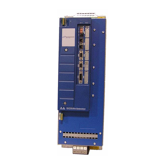
- Page 125 MMC Smart Drive Hardware Manual 460V 3 PHASE MMC SMART DRIVE NEXTGEN Figure 6-1: Front Panel, SDN Drives +24V CAUTION Risk of Electrical Shock High voltage may exist up to 5 minutes after removing power Kollmorgen - June 2014...
-
Page 126: Control Section Connectors, Switches, Leds
As an example, rotating S1 to a setting of 2 equals the value of 20 (2 x 10). Rotating S2 to a setting of 5 equals the value of 5. The actual address setting is 25 (20 + 5). (10s) (1s) Kollmorgen - June 2014... -
Page 127: Digital Link Ports
Transmits data to con- Transmit Data + nected drives. Transmits data to con- Transmit Data - nected drives. Provides a path for the Protective Connector ground signal to an exter- Connector Shell Ground Shell nal single point ground. Kollmorgen - June 2014... - Page 128 OUT Connector “OUT” Transmit + LINK Transmit - Receive + Not Used Not Used Receive - Not Used Not Used Provides a path for the Connector ground signal to an ex- Shield ternal single point ground. Kollmorgen - June 2014...
-
Page 129: Feedback Connectors (F1 & F2)
Available Breakout Boxes and Cables are described in Table 6-10. • Breakout Box dimensions are shown in Figure 6-2 • Breakout Board dimensions are shown in Figure 6-3 • Feedback Port to Motor Cables are described in section 6.1.4.2 on page 137 • Kollmorgen - June 2014... -
Page 130: Kollmorgen - June
PROVIDING 8VDC ENCODER POWER Some Encoders, specifically the Stegmann Hiperface, require 8VDC power to operate. 8VDC Power can be provided on pins 10 and 11 by connecting the +5V Sense Lines (pins 4 & 5) together. Kollmorgen - June 2014... - Page 131 Pins 6 and 7 are In/Out for Hiperface, Endat, and SFD; Inputs for Digital Incremental and BiSS; and Out- puts for Resolver g. Temperature inputs (pins 8 and 9) are shared with the F2 connector h. Hiperface requires +8Vdc. To supply +8V from pin 10, connect +5V Sense lines (pins 4 & 5) together. Kollmorgen - June 2014...
- Page 132 These inputs are shared with F1. +5V Encod- Regulated +5VDC for powering er Power +5V Source the attached encoder (200ma Output max). Signal and Return path for feedback sig- Power Com- Common nals and +5V power output Kollmorgen - June 2014...
- Page 133 F2 is configured for Emulated Encoder Output, and an Input/Output when F2 is configured for SFD. c. This pin is an Input when F2 is configured for Encoder Input, and an Output when F2 is configured for Emulated Encoder Output. Kollmorgen - June 2014...
-
Page 134: Feedback Connectors (F1 And F2) Details
To accept SFD feedback device signals • Hall sensor inputs are only available on the F2 connector • Refer to Table 6-8 for more information regarding the valid combinations of feed- back on the F1 and F2 connectors. Kollmorgen - June 2014... - Page 135 • Endat 2.1 (single or multi-turn) • • Stegmann Hiperface (single or multi- turn) • BiSS (single or multi-turn) a. The F2 connector can support an Encoder input or Emulated F1 Encoder Output, but not both Kollmorgen - June 2014...
- Page 136 Green Twisted Sine/, Sin- White/Green Pair Cos, Cos+ Orange Twisted Cos/, Cos- White/Orange Pair Shell Shield a. Hall signals S1, S2, and S3 are only available on F2 b. Pins 10 & 11 are 16 AWG Kollmorgen - June 2014...
- Page 137 Figure 6-2 on page 136) is DIN-rail mounted, and pro- vides screw terminal wire termination. Use one of the cables listed in the table to connect between the F1 and/or F2 connector and the Breakout Box. Kollmorgen - June 2014...
- Page 138 MMC Smart Drive Hardware Manual 460V 3 PHASE MMC SMART DRIVE NEXTGEN Figure 6-2: Feedback Port (F1 and F2) Breakout Box Dimensions Figure 6-3: Feedback Port (F1 and F2) Breakout Board Dimensions Kollmorgen - June 2014...
-
Page 139: Feedback Port (F1/F2) To Motor Cables
6.1.4.2 Feedback Port (F1/F2) to Motor Cables Cables are available that allow easy connection between the F1 & F2 Feedback Ports and various Kollmorgen motors. These cables are outlined in Table 6-11. The wiring diagram for each cable is located in the indicated Table. For information on Non-Flex versus Hi-Flex cables, refer to section 10.1 on page... - Page 140 Inner Braid Outer Braid Shell Shield Shell Shield 11-14 a. Only applicable to F2 connector b. There are two wires in pin10 c. There are two wires in pin 7 d. This wire is 22 AWG Kollmorgen - June 2014...
- Page 141 White/Grey Outer Braid Shell Shield Shell Shield 6,10,12,16,17 a. This wire is 22 AWG b. There are two wires in pin 4 c. There are two wires in pin 2 d. This wire is 16 AWG Kollmorgen - June 2014...
- Page 142 Wire Color Signal Type Signal Type Number Number Yellow Sin+ Sin+ White/Yellow Sin- Sin- Blue White/Blue Cos- Cos- Black Carrier+ Carrier+ White/Black Carrier- Carrier- Temperature+ Temperature+ White/Red Temperature- Temperature- Outer Braid Shell Shield Shell Shield 1,10-12 1-5,10,11 Kollmorgen - June 2014...
- Page 143 +5V Source +5V Source Common Common Drain Com- Com- Green Com+ Com+ White Inner Braid Shield Outer Braid Shell Shield Shell Shield 6-12 1-5,12-15 a. This wire is 22 AWG b. This wire is 24 AWG Kollmorgen - June 2014...
-
Page 144: Drive I/O Connectors (Io1 & Io2)
General Purpose Inputs, and two General Purpose Outputs (wiring example shown in See Figure 6-4 on page 145). • Pin descriptions are provided in Table 6-16 • Pin assignments are provided in Table 6-17 Kollmorgen - June 2014... - Page 145 Sourcing 7, 8, 9 able Inputs This pin determines whether the General Purpose General Purpose In- Inputs are sourcing (this pin connected to 24 Vdc) puts Sink/Source or sinking (this pin connected to 24 Vdc Common) Kollmorgen - June 2014...
- Page 146 Input 1 Return GPIN2 Input 2 GPOUT1 Output 1 GPIN3 Input 3 GPOUT2 Output 2 GPOUT GPIN4 Input 4 24VDC GPOUT GPIN5 Input 5 24VDC Re- turn GPIN6 Input 6 Relay Output 3 GPIN Sink/ Source Kollmorgen - June 2014...
- Page 147 Sourcing-type Device RELAY IO1-9 Power From Drive Source IO1-10 RELAY Load Analog IO1-3 Analog Out From Drive Input IO1-4 Analog Out Ret Device Analog In + IO1-2 External Drive Source Analog In - IO1-1 Drive Kollmorgen - June 2014...
-
Page 148: Power Section Connectors
3. The application controls the motor as desired 4. The drive is disabled via the Application Program 5. The external user-supplied circuit removes 24Vdc from the "EN" input 6. The process is repeated starting with step 1 above as required Kollmorgen - June 2014... -
Page 149: Ac Power Connector
If single-phase power is used, L1 must be connected to "hot", and L2 must be connected to "neutral". L3 may remain unconnected. 6.2.2.1 Line Fusing Table 6-20 for information on recommended fuses and holders. See section 4.2 on page 40 for additional information on Drive Protection. Kollmorgen - June 2014... -
Page 150: Motor/Brake Connector
Power W- Phase from the drive to the mo- tor. a. This output can be defined and used as a General Purpose Output in PiCPro (Output3), but is typically defined as the Motor Brake Control. Kollmorgen - June 2014... - Page 151 Use of a diode (as shown) or an external RC type snubber is highly recom- mended for use with inductive loads, especially DC inductive loads. Figure 6-5: BR+ and BR- Wiring Examples Using External Power Source Drive Brake Control +24VDC Brake 1N4004 +24V COM Kollmorgen - June 2014...
-
Page 152: Motor/Brake Cables
Kollmorgen AKM/DDR motors. These cables are outlined in Table 6- 22. For a detailed description of these cables, refer to the Kollmorgen “AKD/S700 Accessories Manual” which can be found at www.kollmorgen.com. For information on Non-Flex versus Hi-Flex cables, refer to section 10.1 on page... -
Page 153: Dc Bus/Regen Connector
Available external regen resistors are outlined in Table 6-25. For a detailed description of these resistors, including mounting information, refer to the Kollmorgen “AKD/S700 Accessories Manual” which can be found at www.kollmorgen.com. Kollmorgen - June 2014... - Page 154 23, 600W Cont. Power, 960W Peak Power BAR-600-23 23, 1kW Cont. Power, 1.6kW Peak Power BAR-1000-23 MMC-SDN-14.4- 23, 2kW Cont. Power, 3.2W Peak Power BAS-2000-23 460-D 23, 3kW Cont. Power, 4.8kW Peak Power BAS-3000-23 23, 4kW Cont. Power, 6.3kW Peak Power BAS-4000-23 Kollmorgen - June 2014...
-
Page 155: Specifications - 460V Mmc Smart Drive Nextgen
Pollution Pollution level 2 per IEC 60644-1 Vibration Limits (per IEC 68-2-6) 10-57 Hz (constant amplitude.15 mm) Operating/Non-operating 57 - 2000 Hz (acceleration 2 g) Shock (per IEC 68-2-27) Four shocks per axis (15g/11 msec) Non-operating Kollmorgen - June 2014... - Page 156 150, provided internally Maximum input voltage 5V peak to peak differential -10 to +13.2V common mode Maximum input signal frequency 720 K Hz (2.88 M feedback counts per second) +5V regulated output F1 = 350ma, F2 = 200ma Kollmorgen - June 2014...
- Page 157 Guaranteed On 15 VDC Guaranteed Off 5 VDC Time delay on 1 ms max. (3us for Fast Inputs) Time delay off 1 ms max (50us for Fast Inputs) Input voltage Nominal 24 VDC, maximum 30 VDC Kollmorgen - June 2014...
- Page 158 Configuration Solid State Switch Maximum current 1.5A (3A, 6A, 12A Drive), 2A (24A Drive) Voltage range 24VDC +/-10% Time delay on for resistive loads 50 µsec. max Time delay off for resistive loads 50 µsec. max Kollmorgen - June 2014...
- Page 159 MMC-SD’s “Out” port. Sends and receives high speed data to and from connect- “Out” port ed MMC-SD’s “In” port. Shielded, Straight Pinned, CAT5 or better (CAT5e, CAT6, Cable Type etc.) Maximum Cable Length 30 m (98.4 ft) Kollmorgen - June 2014...
-
Page 160: Physical And Electrical Data
C to 55 C (104 F to 131 Output Current (Amps) Continuous RMS Continuous 0-Peak Peak 0-Peak 12.7 25.5 42.5 67.9 Continuous Output Power Input = 240 VAC, 1.25 Input = 400 VAC, Input = 480 VAC, Kollmorgen - June 2014... -
Page 161: Dimensions
When locating the drive on the panel, observe the clearance requirements found in Table 3-1 on page 21. Mount the drive to the panel with #10 bolts and #10 star washers (to ensure proper ground connection). Kollmorgen - June 2014... - Page 162 .197 in .50 in (5 mm) (12.70 mm) .413 in (10.5 mm) .276 in (7 mm) 10.08 in 9.57 in (256 mm) (243 mm) .197 in (5 mm) Depth (to front surface of Drive): 7.375" (188mm) Kollmorgen - June 2014...
- Page 163 (5.5 mm) (12.70 mm) .433 in (11 mm) .354 in (9 mm) 12.05 in 11.50 in (306 mm) (292 mm) .217 in (5.5 mm) (x2) 2.126 in (54 mm) Depth (to front surface of Drive): 9.125" (232mm) Kollmorgen - June 2014...
- Page 164 MMC Smart Drive Hardware Manual 460V 3 PHASE MMC SMART DRIVE NEXTGEN Kollmorgen - June 2014...
-
Page 165: 1/3 Phase Mmc Smart Drive
This connector can support one of the following functions: • Emulated F1 encoder output • Comcoder Input (Incremental Encoder with halls). Note that on non- Enhanced Feedback models, halls can be connected to F1 or F2, but not both. Kollmorgen - June 2014... - Page 166 Command Input (Analog Interfaced MMC-SD only) • General purpose Analog Input (Digital MMC-SD only) • Digital Link digital connections (Digital MMC-SD only) • Optional MMC-SD Control (for Digital MMC-SD only) • • UL Listed and CE Marked. Kollmorgen - June 2014...
- Page 167 Three Phase This section not on CAUTION - Risk of Electric Shock Drive Only Narrow Drive High Voltage may exist up to 10 minutes after removing power DC Bus/Regen Terminal Strip (4-Position Pluggable Screw Terminal Strip) Kollmorgen - June 2014...
-
Page 168: Control Section Connectors, Switches, Leds
PiCPro programming interface. • Pin descriptions for are provided in Table 7-2 • Pin assignments are provided in Table 7-3 • The available PiCPro Port to PC cable is described in Table 7-4 Kollmorgen - June 2014... - Page 169 Shell Table 7-3: PiCPro Port Pin Assignments Signal In/Out Connector Pinout RS232 Receive Data 6-pin Female RS232 Transmit Data Miniature Circular DIN Signal Ground In/Out Signal Ground In/Out Connector Shield Shield Kollmorgen - June 2014...
-
Page 170: Picpro Port (Analog Drives)
PiCPro programming interface. Pin descriptions for are provided in Table 7-5 • Pin assignments are provided in Table 7-6 • The available PiCPro Port to PC cable is described in Table 7-7 • Kollmorgen - June 2014... - Page 171 Always high (tied to +12V through 1K resistor) Ready Request-to-send Always high (tied to +12V through 1K resistor) Provides a path for shield current through the Connector Shield Ground chassis to an external single point ground. Shell Kollmorgen - June 2014...
- Page 172 MMC Smart Drive Hardware Manual 230V 1/3 PHASE MMC SMART DRIVE Table 7-6: PiCPro Port Pin Assignments Signal In/Out Connector Pinout RS232 Receive Data RS232 Transmit Data 9-pin male D-sub Data Terminal Ready Signal Ground In/Out Request-to-send Connector Drain Shield Kollmorgen - June 2014...
-
Page 173: Node Address Rotary Switch (Digital Interfaced Mmc-Sd Only)
As an example, rotating the switch to a setting of 2 on the top switch equals the value of 20 (2 x 10). Rotating the switch on the bottom switch to a setting of 5 equals the value of 5. The actual address setting is 25 (20 + 5). Kollmorgen - June 2014... -
Page 174: Digital Link Ports (Digital Interfaced Mmc-Sd Only)
Transmits data to con- Transmit Data + nected drives. Transmits data to con- Transmit Data - nected drives. Provides a path for the Protective Connector ground signal to an exter- Connector Shell Ground Shell nal single point ground. Kollmorgen - June 2014... - Page 175 OUT Connector LINK LINK Transmit + Transmit - Receive + Not Used Not Used Receive - Not Used Not Used Provides a path for the Connector ground signal to an ex- Shield ternal single point ground. Kollmorgen - June 2014...
-
Page 176: Feedback Connectors (F1 & F2)
Available Breakout Boxes and Cables are described in Table 7-17. • Breakout Box dimensions are shown in Figure 7-2 • Breakout Board dimensions are shown in Figure 7-3 • Feedback Port to Motor Cables are described in section 7.1.6.2 on page 184 • Kollmorgen - June 2014... - Page 177 Sinewave Encoders used Ref Mark, Ref Mark/ 5, 10 ence Mark Input to indicate motor position within one revolution. Return path for feedback sig- Signal and Power Com- Common nals and power supplies (+5V and +9V). Kollmorgen - June 2014...
- Page 178 Pins 5 and 10 are In/Out for Stegmann Hiperface and Endat; Inputs for Digital Incremental, SSI, BiSS, Heidenhain Sincoder; and Outputs for Resolver f. Not available on Enhanced Feedback drives g. Pins 12 and 13 are Outputs for ENDAT, SSI, and BiSS Kollmorgen - June 2014...
- Page 179 Regulated +9VDC for powering the at- +9V Encoder Power Outputs tached encoder (F1 pin 7 + F2 pin 7 = 150ma max). Return path for feedback signals and pow- Signal and Power Common er supplies (+5V and 9 V). Kollmorgen - June 2014...
- Page 180 230V 1/3 PHASE MMC SMART DRIVE Table 7-14: Pin Assignments for Feedback Connector (F2) (Digital Interfaced MMC-SD Only) Label In/Out Connector Pinout 15-pin Female HD D-Sub Common In/Out Do Not Connect Temperature Do Not Connect Shell Shield Kollmorgen - June 2014...
-
Page 181: Feedback Connectors (F1 And F2) Details
Comcoder to be connected to F2, while simultaneously allowing any supported feedback device to be connected to F1. • Refer to Table 7-15 for more information regarding the valid combinations of feed- back on the F1 and F2 connectors. Kollmorgen - June 2014... - Page 182 On a Enhanced Feedback drive, commutation halls cannot be connected to F1 b. On a Enhanced Feedback drive, an Incremental Encoder with Halls can be con- nected to F2 while optionally any supported feedback device is connected to F1 Kollmorgen - June 2014...
- Page 183 Common (16 AWG) White/Gray Pair +9V Source Brown Twisted White/Brown Pair Temperature Green Twisted White/Green Pair Commutation Track S1, RS-485 Clock+, Violet Twisted Commutation Sin+ Commutation Track S2, RS-485 Clock-, White/Violet Pair Commutation Sin- Shell Drain Kollmorgen - June 2014...
- Page 184 Figure 7-2 on page 183) is DIN-rail mounted, and pro- vides screw terminal wire termination. Use one of the cables listed in the table to connect between the F1 and/or F2 connector and the Breakout Box. Kollmorgen - June 2014...
- Page 185 MMC Smart Drive Hardware Manual 230V 1/3 PHASE MMC SMART DRIVE Figure 7-2: Feedback Port (F1 and F2) Breakout Box Dimensions Figure 7-3: Feedback Port (F1 and F2) Breakout Board Dimensions Kollmorgen - June 2014...
-
Page 186: Feedback Port (F1/F2) To Motor Cables
230V 1/3 PHASE MMC SMART DRIVE 7.1.6.2 Feedback Port (F1/F2) to Motor Cables Several cables are available that allow easy connection between the Feedback Port (F1/F2) and various Kollmorgen motors. These cables are detailed in Table 7-18 through Table 7-29. For information on Non-Flex versus Hi-Flex cables, refer to section 10.1 on page... - Page 187 Blue White/Blue SIN/ Black DATA+ DATA White/Black DATA- DATA/ Violet CLOCK+ CLOCK White/Violet CLOCK- CLOCK/ UnSENSE VCC White/Red UnSENSE COM Green TEMPERATUR THERMAL White/Green THERMAL Orange White/Orange Brown 9 VDC White/Brown Gray +5 VDC 5VDC White/Gray Kollmorgen - June 2014...
- Page 188 1 M (3.3 ft M.1302.8618 M.1302.8630 3 M (9.8 ft) M.1302.8439 M.1302.8450 6 M (19.7 ft) M.1302.8619 M.1302.8631 9 M (29.5 ft) M.1302.8620 M.1302.8632 15 M (49.2 ft) M.1302.8621 M.1302.8633 30 M (98.4 ft) M.1302.8622 M.1302.8634 Kollmorgen - June 2014...
- Page 189 Color Number Type Number Connections Type Black COS+ COS+ White/Black COS- COS- SIN+ SIN+ White/Red SIN- SIN- Green REF+ REF+ White/Green REF- REF- Orange TEMP+ TEMP+ White/Orange TEMP- 9 VDC 9 VDC +5 VDC +5 VDC Kollmorgen - June 2014...
- Page 190 1 M (3.3 ft) M.1302.8590 M.1302.8600 3 M (9.8 ft) M.1302.8447 M.1302.8435 6 M (19.7 ft) M.1302.8591 M.1302.8601 9 M (29.5 ft) M.1302.8542 M.1302.8602 15 M (49.2 ft) M.1302.8594 M.1302.8603 30 M (98.4 ft) M.1302.8595 M.1302.8604 Kollmorgen - June 2014...
- Page 191 Wire Jumper Signal Type Signal Type Color Number Number Connections Yellow White/Yellow Blue White/Blue Black White/Black Violet White/Violet White/Red Green TEMPERATURE TEMPERATURE+ White/Green TEMPERATURE- Orange White/Orange Brown 9 VDC White/Brown Gray +5 VDC +5 VDC White/Gray Kollmorgen - June 2014...
- Page 192 Table 7-25 on page 191 Length Non-Flex P/N Hi-Flex P/N 1 M (3.3 ft) M.1302.0944 M.1302.5834 3 M (9.8 ft) M.1302.0945 M.1302.5835 9 M (29.5 ft) M.1302.0946 M.1302.5836 15 M (49.2 ft) M.1302.0947 M.1302.5837 30 M (98.4 ft) M.1302.0948 M.1302.5838 Kollmorgen - June 2014...
- Page 193 Signal Type Signal Type Color Number Number Connections Yellow White/Yellow Blue White/Blue Black White/Black Violet White/Violet White/Red Green TEMPERATURE TEMPERATURE+ White/Green TEMPERATURE- Orange White/Orange Brown 9 VDC 9 VDC White/Brown Gray +5 VDC +5 VDC White/Gray Kollmorgen - June 2014...
- Page 194 Table 7-27 on page 193 Length Non-Flex P/N Hi-Flex P/N 1 M (3.3 ft) M.1301.3927 3 M (9.8 ft) M.1301.4011 9 M (29.5 ft) M.1301.4012 15 M (49.2 ft) M.1301.4013 30 M (98.4 ft) M.1301.4014 Kollmorgen - June 2014...
- Page 195 Connector to Motor Drive Twisted Pair, 28 AWG 16 AWG Wire Jumper Signal Type Signal Type Color Number Number Connections Black White/Black White/Red Green White/Green Gray +5VDC +5VDC White/Gray TEMPERATURE- Blue White/Blue Brown White/Brown TEMPERATURE TEMPERATURE+ White/Violet Kollmorgen - June 2014...
- Page 196 Table 7-29 on page 195 Length Non-Flex P/N Hi-Flex P/N 1 M (3.3 ft) M.1301.3983 2 M (6.6 ft) M.1302.7675 3 M (9.8 ft) M.1301.3984 9 M (29.5 ft) M.1301.3985 15 M (49.2 ft) M.1301.3986 30 M (98.4 ft) M.1301.3987 Kollmorgen - June 2014...
- Page 197 Connector to Motor Drive Twisted Pair, 28 AWG 16 AWG Wire Signal Jumper Signal Color Number Type Number Connections Type Black White/Black White/Red Green White/Green Gray +5VDC White/Gray Blue White/Blue NO JUMPERED PINS Brown White/Brown 25-28 Kollmorgen - June 2014...
-
Page 198: Drive I/O Connector (Io)
F1connector is filtered and processed. General Purpose 24VDC sourcing type. Default assignment: 23, 24, Software Assign- Pin 26 (GPOUT4) = Drive Ready 25, 26 able Outputs IO24V, IO24COM 24 VDC inputs for powering GPIN and GPOUT I/O. 10, 16 Kollmorgen - June 2014... - Page 199 Input1 FDBK1B I GPIN2 Input2 FDBK1B I/ GPIN3 Input3 Shield GPIN4 Input4 GPIN7 + GPIN5 Input5 Input7 GPIN7 - GPIN6 Input6 IO24V GPOUT1 Output1 GPIN8 + GPOUT2 Output2 Input8 GPIN8 - GPOUT3 Output3 Shield GPOUT4 Output4 Kollmorgen - June 2014...
- Page 200 DCOUT1 White/Yellow DCOUT2 Brown White/Brown DCOSS Violet White/Violet Gray IO24V 24VDCOUT White/Gray IOCOM Shell Shield Shell Shield a. These cables are only used to interface between the Analog MMC-An control and the Analog MMC Smart Drive. Kollmorgen - June 2014...
- Page 201 GPIN7 + Blue Twisted GPOUT3 Gry/Blu Twisted GPIN7 - Blu/Wht Pair GPOUT4 Yel/Blu Pair GPIN8 + Yellow Twisted IO24V Gray Twisted GPIN8 - Yel/Wht Pair IO24C Gry/Wht Pair CMD + Brown Twisted CMD - Brn/Wht Pair Kollmorgen - June 2014...
- Page 202 The Drive I/O Breakout Box (see Figure 7-4 on page 201) is DIN-rail mounted, and provides screw terminal wire termination. Use one of the cables listed in the table to connect between the IO connector and the Break- out Box. Kollmorgen - June 2014...
- Page 203 MMC Smart Drive Hardware Manual 230V 1/3 PHASE MMC SMART DRIVE Figure 7-4: Drive I/O Port Breakout Box Dimensions Figure 7-5: Drive I/O Port Breakout Board Dimensions Kollmorgen - June 2014...
- Page 204 MMC or other Drive External CMD - Source (On the Digital Interfaced MMC-SD, this is a General Purpose Analog Input) FDBK1B A, B, I MMC or other From F1 External Connection Control FDBK1B A/, B/, I/ Drive Kollmorgen - June 2014...
-
Page 205: Power Section Connectors
MMC Smart Drive Hardware Manual 230V 1/3 PHASE MMC SMART DRIVE Power Section Connectors This section describes the connectors located on the Power Section (left portion) of the drive. Kollmorgen - June 2014... -
Page 206: 24 Vdc In/Brake Connector
(See sec- Drive Enable tion 7.2.1.1 on page 205). Must be con- Protective nected to Pro- Ground tective Earth Ground (SPG) Brake Relay + Out- Refer to Figure put5/ Figure 7-7. Relay Brake Relay - Kollmorgen - June 2014... -
Page 207: En" Requirements And Safe-Off Operation
2. The drive is enabled via the Application Program 3. The application controls the motor as desired 4. The drive is disabled via the Application Program 5. The external user-supplied circuit removes 24Vdc from the "EN" input Kollmorgen - June 2014... -
Page 208: Power Connector
AC power and the motor that is being controlled by the Drive. ADDITIONAL SHUNT RESISTOR INFORMATION Refer to section 4.5 on page 60 for instructions on choosing, mounting, and connecting Shunt Resistors available from Kollmorgen. Kollmorgen - June 2014... - Page 209 Ground (SPG). Power U-phase from the drive to the motor. Power V-phase from the drive to Motor Power the motor. Power W- Phase from the drive to the mo- tor. Protective Connection for Ground motor ground. Kollmorgen - June 2014...
- Page 210 If 110Vac single-phase power is used, the incoming 110Vac “hot” must be connected to L1, and “neutral” must be connected to L2. L3 may remain unconnected. If 230Vac single-phase power is used, the incoming 230Vac must be connected to • L1 and L2. L3 may remain unconnected. Kollmorgen - June 2014...
-
Page 211: Dc Bus/Regen Connector (3-Phase Drive Only)
DC Bus and to an external Regen resistor. ADDITIONAL SHUNT RESISTOR INFORMATION Refer to section 4.5 on page 60 for instructions on choosing, mounting, and connecting Shunt Resistors available from Kollmorgen. Table 7-38: Pin Assignment Bus/Regen Connector Three Phase Drive Only Terminal Signal... -
Page 212: Specifications - 230V Mmc Smart Drive
5V peak to peak differential -10 to +13.2V common mode Maximum input signal frequency 720 K Hz (2.88 M feedback counts per second) +5V regulated output 500ma max between F1 and F2 +9V regulated output 150ma max between F1 and F2 Kollmorgen - June 2014... - Page 213 Analog Input On the Analog Interfaced MMC-SD: • Analog velocity or torque, 0 to + 10V • 14 bit effective resolution Analog Input On the Digital MMC-SD: • General Purpose Analog Input • 14 bit effective resolution Kollmorgen - June 2014...
- Page 214 93/68/EEC) and EMC Directive 89/336/EEC (amend- CE Marked (only for Single Phase ed by 92/31/EEC and 93/68/EEC). Drives. Three Phase Drives pending). Conformance is in accordance with the following stan- dards: EN 50178 and EN61800-3 UL and C/UL Listed E233454 Kollmorgen - June 2014...
-
Page 215: Physical And Electrical Data For 230V Drives
Nominal Input Current 5 (3) 9 (5) 18 (10) 18 (14) Amps RMS Maximum Inrush 70 (70) 70 (70) 70 (70) 70 (70) Amps 0-Peak Power Loss, Watts 22 (22) 37 (37) 70 (70) 90 (90) Kollmorgen - June 2014... - Page 216 Maximum 250 VAC / 100 VDC switching voltage Maximum 5 A (AC) / 2.5 A (DC) switching current Energy Absorbtion Specifications DC Bus Capacitance 1410 F 1880 F (Internal) Bus overvoltage 420 VDC threshold Kollmorgen - June 2014...
-
Page 217: Dimensions For 230V Mmc Smart Drive
When locating the drive on the panel, observe the clearance requirements found in Table 3-1 on page 21. Mount the drive to the panel with #10 bolts and #10 star washers (to ensure proper ground connection). Kollmorgen - June 2014... - Page 218 230V 1/3 PHASE MMC SMART DRIVE Figure 7-8: 500 W Narrow Drive (-DN) - Front View 2.49 in (63.25 mm) .50 in 1.49 in (37.85 mm) (12.70 mm) 9.69 in (246.13 mm) 2.96 in (75.18 mm) Kollmorgen - June 2014...
- Page 219 MMC Smart Drive Hardware Manual 230V 1/3 PHASE MMC SMART DRIVE Figure 7-9: 500 W Standard Drive (non-DN) - Front 3.22 in (81.74 mm) 2.22 in .50 in (56.34 mm) (12.70 mm) 9.69 in (246.13 mm) 3.69 in (93.73 mm) Kollmorgen - June 2014...
- Page 220 230V 1/3 PHASE MMC SMART DRIVE Figure 7-10: 1, 2, and 3 kW Narrow Drive (-DN) - Front View 2.49 in (63.25 mm) 1.49 in .50 in (37.85 mm) (12.70 mm) 9.69 in (246.13 mm) 3.96 in (100.59 mm) Kollmorgen - June 2014...
- Page 221 230V 1/3 PHASE MMC SMART DRIVE Figure 7-11: 1, 2 and 3 kW Standard Drive (non-DN) - Front View 3.22 in (81.74 mm) 2.22 in .50 in (56.34 mm) (12.70 mm) 9.69 in (246.13 mm) 4.69 in (119.05 mm) Kollmorgen - June 2014...
- Page 222 MMC Smart Drive Hardware Manual 230V 1/3 PHASE MMC SMART DRIVE Figure 7-12: 230V Standard (non -DN) and Narrow (-DN) Drive - Side View 6.12 in (155.56 mm) 10.13 in (257.18 mm) 8.79 in (223.27 mm) Kollmorgen - June 2014...
-
Page 223: 3-Phase Mmc Smart Drive
Control Section Connectors, Switches, LEDs The Control Section is located on the right side of the drive, and is identical to the Control Section on the 230V Smart Drive. Refer to section 7.1 on page 166 Kollmorgen - June 2014... -
Page 224: Power Section Connectors
The functionality and descriptions for the switches and connectors on the Control Section of the 460V MMC Smart Drives are the same as those on the 230V MMC Smart Drive. Refer to section 7.1 on page 166 for more information. Kollmorgen - June 2014... - Page 225 (IN/OUT) Feedback Feedback Connector (F1) Connector (F1) Feedback Not Used Connector (F2) Drive I/O Drive I/O Connector (IO) Connector (IO) *See Section 5.1 *See Section 5.1 Motor Brake Connector (X101) +24VBRK Brake+ Brake- Motor 24VCOM Connector Kollmorgen - June 2014...
-
Page 226: Shunt/Dc Bus Connector
1D1 (ZK-) Note: A 4-pin screw-terminal mating connector is included with the drive. Additional connectors (P/N M.1302.7159) are available from Kollmorgen. NOTE The shunt resistor (if installed) across Ba+ and Ba- will be connected across the DC bus when the DC bus reaches the “shunt switch threshold” as shown in the specification table;... -
Page 227: Ac Power Connector
Y sys- tem. Note: A 4-pin screw-terminal mating connector is included with the drive. Additional connectors (P/N M.1302.7158) are available from Kollmorgen. a. See important note regarding Input Power Phasing below NOTE When wiring Input Power to the drive, proper phasing is required. Specifical- ly, it is necessary that U leads V, and V leads W. -
Page 228: Power Connector (J1)
24V Com Note: A 6-pin cage-clamp mating connector is included with the drive. Additional connectors (P/N M.1302.7099) are available from Kollmorgen. a. As an Output, indicates that the AC Input Power to the drive is OK. As an Input, instructs the drive to run even though AC Input Power is not present. This is typ- ically used when two drives share bus power that is provided by the drive con- nected to AC Input Power. -
Page 229: Motor Brake Connector (X101)
24 VDC com- Power 24VCOM Not Used. Used Note: A 6-pin cage-clamp mating connector is included with the drive. Additional connectors (P/N M.1302.7099) are available from Kollmorgen. Figure 8-2: Wiring Example for X101 Connector Drive Connector +24VBRK +24V BRAKE +... - Page 230 Feedback Feedback Connector (F1) Connector (F1) Feedback Not Used Connector (F2) Drive I/O Drive I/O Connector (IO) Connector (IO) *See Section 5.1 *See Section 5.1 Motor Power Connector Motor Brake Connector (X101) +24VBRK Brake+ Brake- 24VCOM Kollmorgen - June 2014...
-
Page 231: Ac Power Connector
Connect L1 to U, L2 to V, and L3 to W. If, when the drive is powered up and enabled, the drive indicates an Error 35 (Drive Power Module Fault, as indicated on the Drive Status Light and in PiCPro), remove power from the drive, and swap the U and V connections. Kollmorgen - June 2014... -
Page 232: Motor Connector
Connector Signal Type Description Label In/Out Connector Protective Ground Ground (Earth) Power U-phase from the drive to the motor Power V-phase Motor from the drive to the motor Power W-phase from the drive to the motor Kollmorgen - June 2014... -
Page 233: Power Connector (J1)
24V Com Note: A 6-pin cage-clamp mating connector is included with the drive. Additional connectors (P/N M.1302.7099) are available from Kollmorgen. a. As an Output, indicates that the AC Input Power to the drive is OK. As an Input, instructs the drive to run even though AC Input Power is not present. This is typically used when two drives share bus power that is provided by the drive connected to AC Input Power. -
Page 234: Size 3 Power Section Connectors
(supply and mag- 24VCOM net) Not Used. Used Note: A 6-pin cage-clamp mating connector is included with the drive. Additional connec- tors (P/N M.1302.7099) are available from Kollmorgen. Figure 8-4: Wiring Example for X101 Connector Drive Connector +24VBRK +24V BRAKE +... - Page 235 Connector (F1) Connector (F1) Feedback Not Used Connector (F2) Drive I/O Drive I/O Connector (IO) Connector (IO) *See Section 5.1 *See Section 5.1 Motor Power Connector Motor Brake Connector (X101) (Located under cover) +24VBRK Brake+ Brake- 24VCOM Kollmorgen - June 2014...
-
Page 236: Ac Power Connector
Connect L1 to U, L2 to V, and L3 to W. If, when the drive is powered up and enabled, the drive indicates an Error 35 (Drive Power Module Fault, as indicated on the Drive Status Light and in PiCPro), remove power from the drive, and swap the U and V connections. Kollmorgen - June 2014... -
Page 237: Motor Connector
Signal Connector Type Description Label In/Out Connector Protective Ground Ground (Earth) Power U-phase from the drive to the motor Power V-phase from the drive to the motor Motor Power W-phase from the drive to the motor Kollmorgen - June 2014... -
Page 238: Power Connector (J1)
24V Com Note: A 6-pin cage-clamp mating connector is included with the drive. Additional connectors (P/N M.1302.7099) are available from Kollmorgen. a. As an Output, indicates that the AC Input Power to the drive is OK. As an Input, instructs the drive to run even though AC Input Power is not present. This is typ- ically used when two drives share bus power that is provided by the drive con- nected to AC Input Power. -
Page 239: Motor Brake Connector (X101)
(supply and mag- 24VCOM net) Not Used. Used Note: A 6-pin cage-clamp mating connector is included with the drive. Additional connec- tors (P/N M.1302.7099) are available from Kollmorgen. Figure 8-6: Wiring Example for X101 Connector Drive Connector +24VBRK +24V BRAKE +... - Page 240 Connector (F1) Feedback Not Used Connector (F2) Drive I/O Drive I/O Connector (IO) Connector (IO) *See Section 5.1 *See Section 5.1 Motor Power Connector Motor Brake Connector (X101) (Located under cover) Connector +24VBRK (X36) Brake+ Brake- 24VCOM Kollmorgen - June 2014...
-
Page 241: Ac Power Connector
Connect L1 to U, L2 to V, and L3 to W. If, when the drive is powered up and enabled, the drive indicates an Error 35 (Drive Power Module Fault, as indicated on the Drive Status Light and in PiCPro), remove power from the drive, and swap the U and V connections. Kollmorgen - June 2014... -
Page 242: Motor Connector
Signal Connector Type Description Label In/Out Connector Protective Ground Ground (Earth) Power U-phase from the drive to the motor Power V-phase from the drive to the motor Motor Power W-phase from the drive to the motor Kollmorgen - June 2014... -
Page 243: Power Connector (J1)
24V Com Note: A 6-pin cage-clamp mating connector is included with the drive. Additional connectors (P/N M.1302.7099) are available from Kollmorgen. a. As an Output, indicates that the AC Input Power to the drive is OK. As an Input, instructs the drive to run even though AC Input Power is not present. This is typ- ically used when two drives share bus power that is provided by the drive con- nected to AC Input Power. -
Page 244: Motor Brake Connector (X101)
(supply and mag- 24VCOM net) Not Used. Used Note: A 6-pin cage-clamp mating connector is included with the drive. Additional connec- tors (P/N M.1302.7099) are available from Kollmorgen. Figure 8-8: Wiring Example for X101 Connector Drive Connector +24VBRK +24V BRAKE +... -
Page 245: Fan Connector (X36)
The functionality and descriptions for the switches and connectors on the Control Section of the 460V MMC Smart Drives are the same as those on the 230V MMC Smart Drive. Refer to section 7.1 on page 166 for more information. Kollmorgen - June 2014... - Page 246 Connector (F1) Feedback Not Used Connector (F2) Drive I/O Drive I/O Connector (IO) Connector (IO) *See Section 5.1 *See Section 5.1 Motor Brake Connector (X101) Power Connector +24VBRK Brake+ Connector Brake- (X36) 24VCOM 1V2 1W2 1U1 1V1 Kollmorgen - June 2014...
-
Page 247: Ac Power Connector
Connect L1 to U, L2 to V, and L3 to W. If, when the drive is powered up and enabled, the drive indicates an Error 35 (Drive Power Module Fault, as indicated on the Drive Status Light and in PiCPro), remove power from the drive, and swap the U and V connections. Kollmorgen - June 2014... - Page 248 Ba- and 1C1 (ZK+) terminals. The shunt resistor will be applied across the DC bus when the DC bus voltage rises above 415 volts, and will be removed when the DC bus voltage falls below 400 volts. Kollmorgen - June 2014...
-
Page 249: Power Connector (J1)
24V Com Note: A 6-pin cage-clamp mating connector is included with the drive. Additional connectors (P/N M.1302.7099) are available from Kollmorgen. a. As an Output, indicates that the AC Input Power to the drive is OK. As an Input, instructs the drive to run even though AC Input Power is not present. This is typ- ically used when two drives share bus power that is provided by the drive con- nected to AC Input Power. -
Page 250: Motor Brake Connector (X101)
(supply and mag- 24VCOM net) Not Used. Used Note: A 6-pin cage-clamp mating connector is included with the drive. Additional connec- tors (P/N M.1302.7099) are available from Kollmorgen. Figure 8-10: Wiring Example for X101 Connector Drive Connector +24VBRK +24V BRAKE +... -
Page 251: Fan Connector (X36)
460V 3-PHASE MMC SMART DRIVE 8.2.5.4 Fan Connector (X36) Table 8-22: 460V Size 5 Fan Connector (X36) Signal Signal Connector Type Description Label In/Out Connector 230VAC Line for Power 230VAC powering the fan 230VAC Neutral Power for powering the Kollmorgen - June 2014... -
Page 252: Typical 460V Drive Connection Layout
460V 3-PHASE MMC SMART DRIVE Typical 460V Drive Connection Layout Optional Shunt Incoming AC Resistor Power (Mains) PE U V W +24V M24V X36-L 230VAC X36-N MMC-SD-460 X101-1 +24V X101-2 X101-3 X101-4 X101-5 X101-6 F1/F2 BRAKE Kollmorgen - June 2014... -
Page 253: Specifications - 460V Mmc Smart Drive)
Maxim 3098 A quad B differential RS422 receiver Encoder signals Differential quadrature Input threshold ±200mV Input termination 150, provided internal Maximum input voltage 5Vpp differential -10 to +13.2V common mode Maximum input signal frequency 720KHz (2.88 M feedback unit count rate) Kollmorgen - June 2014... - Page 254 “In” port MMC-SD’s “Out” port. Sends and receives high speed data to and from connected “Out” port MMC-SD’s “In” port. Shielded, Straight Pinned, CAT5 or better (CAT5e, CAT6, Cable Type etc.) Maximum Cable Length 30m (98.4 ft) Kollmorgen - June 2014...
- Page 255 EEC (amended by 92/31/EEC and 93/68/EEC). CE Marked (Pending on Size 5 & 6) Conformance is in accordance with the following stan- dards: EN 50178 and EN61800-3 UL and C/UL Listed (Pending on Size 5 & E233454 Kollmorgen - June 2014...
-
Page 256: Physical/Electrical Data For 460V Size 1 Smart Drives
AC Output Specifications Continuous Output Current RMS (0- 2.1A (3.0A) 3.9A (5.5A) Peak) Continuous Output Power Input = 230 VAC .65kW 1.2kW Input = 460 VAC 1.3kW 2.4kW Peak Output Current 6.0A 11.0A Amps 0-Peak Output Frequency 0-450Hz Kollmorgen - June 2014... - Page 257 22 joules 460V line input External Shunt Maximum shunt 5.9A (AC) resistor current Minimum shunt 130 resistor Maximum shunt resistor power at 4.5kW minimum shunt resistor a. EF indicates that this drive has the Enhanced Feedback feature Kollmorgen - June 2014...
-
Page 258: Physical/Electrical Data For 460V Size 2 Smart Drives
NOTE: Nominal Input Current is specified for nominal input voltage of 460 VAC. Approximate Current for input voltages between 400 and 480 VAC = (listed current) x input voltage/460 Maximum Inrush 13.2A RMS 20.2A RMS 27.7A RMS Current Power Loss 102W 150W 204W Kollmorgen - June 2014... - Page 259 Shunt Switch 780VDC Threshold Joules available for energy absorption 230V motor w/230V 13 joules 19 joules line input 460V motor w/230V 188 joules 177 joules line input 460V motor w/460V 44 joules 66 joules line input Kollmorgen - June 2014...
- Page 260 Maximum shunt 9A (AC) 9A (AC) 9A (AC) resistor current Minimum shunt 86 60 44 resistor Maximum shunt resistor power at 10kW 14kW minimum shunt resistor a. EF indicates that this drive has the Enhanced Feedback feature Kollmorgen - June 2014...
-
Page 261: Physical/Electrical Data For 460V Size 3 Smart Drives
NOTE: Nominal Input Current is specified for nominal input voltage of 460 VAC. Approximate Current for input voltages between 400 and 480 VAC = (listed current) x 460/input voltage Maximum Inrush 32.2A RMS 39.2A RMS 61.8A RMS Current Power Loss 300W 390W 600W 840W Kollmorgen - June 2014... - Page 262 33 joules 45 joules 55 joules 230V line input 460V motor w/ 206 joules 309 joules 412 joules 502 joules 230V line input 460V motor w/ 76 joules 114 joules 152 joules 185 joules 460V line input Kollmorgen - June 2014...
- Page 263 Maximum shunt 36A (AC) 50A (AC) resistor current Minimum shunt 22 16 resistor Maximum shunt resistor power at 29kW 40kW minimum shunt resistor a. EF indicates that this drive has the Enhanced Feedback feature b. Consult Factory Kollmorgen - June 2014...
-
Page 264: Physical/Electrical Data For 460V Size 4 Smart Drives
NOTE: Nominal Input Current is specified for nominal input voltage of 460 VAC. Approximate Current for input voltages between 400 and 480 VAC = (listed current) x 460/input voltage Maximum Inrush Current Power Loss 1080W 1350W 1740W Kollmorgen - June 2014... - Page 265 Shunt Switch 780VDC Threshold Joules available for energy absorption 230V motor w/ 50.4joules 63.1joules 82joules 230V line input 460V motor w/ 472joules 591joules 768joules 230V line input 460V motor w/ 173joules 218joules 284joules 460V line input Kollmorgen - June 2014...
- Page 266 80kW 80kW minimum shunt resistor Fan (X36 Connector) Input Voltage 230VAC (nominal), 207VAC to 253VAC, 50/60HZ Input Current 1A Max Power Loss a. EF indicates that this drive has the Enhanced Feedback feature b. Consult Factory Kollmorgen - June 2014...
-
Page 267: Physical/Electrical Data For 460V Size 5 Smart Drives
163A RMS NOTE: Nominal Input Current is specified for nominal input voltage of 460 VAC. Approximate Current for input voltages between 400 and 480 VAC = (listed current) x 460/input voltage Maximum Inrush Current Power Loss 3300W Kollmorgen - June 2014... - Page 268 DC Bus Capacitance 6600F (Internal) Shunt Switch 780VDC Threshold Joules available for energy absorption 230V motor w/ 177 joules 230V line input 460V motor w/ 1,659 joules 230V line input 460V motor w/ 613 joules 460V line input Kollmorgen - June 2014...
- Page 269 4.0mm (TBD AWG) Screw Torque N/A (Spring Clip) Input Voltage 230VAC (nominal), 207VAC to 253VAC, 50/60HZ Input Current 1A Max Power Loss a. EF indicates that this drive has the Enhanced Feedback feature b. Consult Factory Kollmorgen - June 2014...
-
Page 270: Physical/Electrical Data For 460V Size 6 Smart Drives
245A RMS NOTE: Nominal Input Current is specified for nominal input voltage of 460 VAC. Approximate Current for input voltages between 400 and 480 VAC = (listed current) x 460/input voltage Maximum Inrush Current Power Loss 4800W Kollmorgen - June 2014... - Page 271 DC Bus Capacitance 6000F (Internal) Shunt Switch 780VDC Threshold Joules available for energy absorption 230V motor w/ 194 joules 230V line input 460V motor w/ 1,824 joules 230V line input 460V motor w/ 674 joules 460V line input Kollmorgen - June 2014...
- Page 272 4.0mm (TBD AWG) Screw Torque N/A (Spring Clip) Input Voltage 230VAC (nominal), 207VAC to 253VAC, 50/60HZ Input Current 1A Max Power Loss a. EF indicates that this drive has the Enhanced Feedback feature b. Consult Factory Kollmorgen - June 2014...
-
Page 273: Dimensions For The 460V Smart Drives
MMC Smart Drive Hardware Manual 460V 3-PHASE MMC SMART DRIVE Dimensions for the 460V Smart Drives Figure 8-11: Size 1 460V Smart Drive - Front View Kollmorgen - June 2014... - Page 274 MMC Smart Drive Hardware Manual 460V 3-PHASE MMC SMART DRIVE Figure 8-12: Size 1 460V Smart Drive - Side View Kollmorgen - June 2014...
- Page 275 MMC Smart Drive Hardware Manual 460V 3-PHASE MMC SMART DRIVE Figure 8-13: Size 2 460V Smart Drive - Front View Kollmorgen - June 2014...
- Page 276 MMC Smart Drive Hardware Manual 460V 3-PHASE MMC SMART DRIVE Figure 8-14: Size 2 460V Smart Drive - Side View Kollmorgen - June 2014...
- Page 277 MMC Smart Drive Hardware Manual 460V 3-PHASE MMC SMART DRIVE Figure 8-15: Size 3 460V Smart Drive - Front View Kollmorgen - June 2014...
- Page 278 MMC Smart Drive Hardware Manual 460V 3-PHASE MMC SMART DRIVE Figure 8-16: Size 3 460V Smart Drive - Side View Kollmorgen - June 2014...
- Page 279 MMC Smart Drive Hardware Manual 460V 3-PHASE MMC SMART DRIVE Figure 8-17: Size 4 460V Smart Drive - Front View 4.72in. 1.38in. (120.00mm) (35.00mm) 25.88in. (655.00mm) 7.5in. (190.00mm) Kollmorgen - June 2014...
- Page 280 MMC Smart Drive Hardware Manual 460V 3-PHASE MMC SMART DRIVE Figure 8-18: Size 4 460V Smart Drive - Side View 26.18in. (665.00mm) 12.71in. (322.63mm) Kollmorgen - June 2014...
- Page 281 MMC Smart Drive Hardware Manual 460V 3-PHASE MMC SMART DRIVE Figure 8-19: Size 5 460V Smart Drive - Front View Kollmorgen - June 2014...
- Page 282 MMC Smart Drive Hardware Manual 460V 3-PHASE MMC SMART DRIVE Figure 8-20: Size 5 460V Smart Drive - Side View Kollmorgen - June 2014...
- Page 283 MMC Smart Drive Hardware Manual 460V 3-PHASE MMC SMART DRIVE Figure 8-21: Size 6 460V Smart Drive - Front View Kollmorgen - June 2014...
- Page 284 MMC Smart Drive Hardware Manual 460V 3-PHASE MMC SMART DRIVE Figure 8-22: Size 6 460V Smart Drive - Side View Kollmorgen - June 2014...
-
Page 285: S200-Dls Drive
The S200-DLS consists of a Base Unit with an S200 Digital Link Option Card installed. The combination of the two components is the S200-DLS Drive. The Base Unit is described in detail in Kollmorgen’s S200 Base Unit Reference Manual, P/N M-SM- 200-01, which can be found at http://www.kollmorgen.com/website/com/eng/products/... - Page 286 MMC Smart Drive Hardware Manual S200-DLS DRIVE Figure 9-1: Kollmorgen - June 2014...
-
Page 287: S200-Dls Option Card
Drive. • The left-most LED is associated with the “DLINK OUT” connector, and indicates that the Drive is connected and successfully communicating with another “down- stream” Digital Link device (Digital Link drive, Digital Link Accessory, etc.). Kollmorgen - June 2014... -
Page 288: Node Address Rotary Switches
As an example, rotating the top switch (S3) to a setting of 2 equals the value of 20 (2 x 10). Rotating the bottom switch (S4) to a setting of 5 equals the value of 5. The actual address setting is 25 (20 + 5). Figure 9-2: Node Address Switches S4 (10s) S3 (1s) Kollmorgen - June 2014... -
Page 289: Digital Link Ports
Receive Data+/- connected drives. Transmits data to con- Transmit Data +/- nected drives. Shield connection. Pro- vides a path for the Protective ground signal to an ex- Connector Shell Connector Shell Ground ternal single point ground. Kollmorgen - June 2014... - Page 290 OUT Connector LINK LINK Transmit + DLINK Transmit - Receive + Not Used Not Used Receive - Not Used Not Used Provides a path for the Connector ground signal to an ex- Shield ternal single point ground. Kollmorgen - June 2014...
-
Page 291: Auxiliary Feedback Port
The available Flying Lead cable is described in Table 9-7. • Available Breakout Boxes and Cables are described in Table 9-8. • Breakout Box dimensions are shown in Figure 9-3 • Breakout Board dimensions are shown in Table 9-4 Kollmorgen - June 2014... - Page 292 In order to use a BiSS encoder with the S200-DLS drive, the drive must be Rev 3 or later (as found on the drive label), and the firmware within the drive must be Version 2.03 or later. Kollmorgen - June 2014...
- Page 293 Version 2.00 or later c. Pins 5 and 10 are In/Out for Endat, and Inputs for Digital Incremental, SSI, and BiSS d. Pins 12 and 13 are Outputs for ENDAT, SSI, and BiSS Kollmorgen - June 2014...
- Page 294 Not Connected White/Green Pair Commutation Track S1, RS-485 Violet Twisted Clock+ Commutation Track S2, RS-485 White/Violet Pair Clock- Not Connected Orange Twisted Not Connected White/Orange Pair Not Used Brown Twisted Not Connected White/Brown Pair Shell Drain Kollmorgen - June 2014...
- Page 295 The Breakout Box (see Figure 9-4 on page 294) is DIN-rail mounted, and pro- vides screw terminal wire termination. Use one of the cables listed in the table to connect between the Aux Feedback connector and the Breakout Box. Kollmorgen - June 2014...
- Page 296 MMC Smart Drive Hardware Manual S200-DLS DRIVE Figure 9-3: Aux Feedback Port Breakout Box Dimensions Figure 9-4: Aux Feedback Port Breakout Board Dimensions Kollmorgen - June 2014...
- Page 297 Blue White/Blue SIN/ Black DATA+ DATA White/Black DATA- DATA/ Violet CLOCK+ CLOCK White/Violet CLOCK- CLOCK/ UnSENSE VCC White/Red UnSENSE COM Green TEMPERATUR THERMAL White/Green THERMAL Orange White/Orange Brown 9 VDC White/Brown Gray +5 VDC 5VDC White/Gray Kollmorgen - June 2014...
- Page 298 Wire Jumper Signal Type Signal Type Color Number Number Connections Yellow White/Yellow Blue White/Blue Black White/Black Violet White/Violet White/Red Green TEMPERATURE TEMPERATURE+ White/Green TEMPERATURE- Orange White/Orange Brown 9 VDC White/Brown Gray +5 VDC +5 VDC White/Gray Kollmorgen - June 2014...
-
Page 299: Drive I/O And I/O Power Ports
9.1.8 on page 299. • Table 9-11: Drive I/O Port Pin Descriptions Function Notes Nominal 24 Vdc Outputs capable of sourcing DC Outputs 1-4 5,6,7,8 up to 50 ma. DC Inputs 5-8 Nominal 24 Vdc sourcing/sinking Inputs 1,2,3,4 Kollmorgen - June 2014... - Page 300 8-Pin plugable Screw J8 Aux Feedback connector) Terminal Connector DC Input 6 DC Input 5 (Data Capture input for DRIVE J3 SFD Feedback connector) DC Output 4 DC Output 3 DC Output 2 DC Output 1 Kollmorgen - June 2014...
-
Page 301: Drive I/O Port Details
Connector Kits that include connectors for the Pow- er Section connectors (J1, J2, J3, and J4) 9.1.8 Drive I/O Port Details There are four DC Inputs and four DC Outputs available for interfacing to various devices. This section explains these Inputs/Outputs in detail. Kollmorgen - June 2014... -
Page 302: Drive I/O Port Outputs
24 Vdc Common, making Drive Inputs 7 and 8 Sourcing. In this con- figuration, one side of the input device is connected to the Input pin on the Drive I/ O Port connector, and the other side of the input device is connected to 24 Vdc. Kollmorgen - June 2014... -
Page 303: Power Section Wiring Accessories
DCIN7 SOURCING DCIN8 5&6 SS 7&8 SS 24VDCIN I/O PWR 24VDC COM CHASSIS 24 Vdc Power Supply Power Section Wiring Accessories This section describes wiring accessories related to the Power Section of the S200- DLS Drives. Kollmorgen - June 2014... - Page 304 01, as described above), plus J6 and J7 (as described in M.3000.0728 Table 9-15 on page 299) a. J2 is not present on the 12A and 24A S200-DLS drives. Connection for Motor Power is provided via a non-pluggable screw-terminal connector. Kollmorgen - June 2014...
-
Page 305: Specifications - S200-Dls Drive
The S200-DLS consists of a Base Unit with an S200 Digital Link Option Card installed. The combination of the two components is the S200-DLS Drive. The Base Unit is described in detail in Kollmorgen’s S200 Base Unit Reverence Manual, P/N M-SM- 200-01, which can be found at http://www.kollmorgen.com/website/com/eng/products/... - Page 306 Note: Only units Rev 1 Conformance is in accordance with the following stan- dards: or higher are CE EN 50178 and EN61800-3 Marked. UL and C/UL Recog- E233454 nized RoHs The S200-DLS Drives are not RoHs compliant Kollmorgen - June 2014...
-
Page 307: Motor Cables & Connectors
MMC Smart Drive Hardware Manual MOTOR CABLES & CONNECTORS Motor Cables & Connectors Kollmorgen offers many cables that connect directly from the MMC Smart Drive’s F1/ F2 connector to various Kollmorgen motors. These cables are described in detail in section 7.1.6.2 on page 184. -
Page 308: Cable Tension
Failure to properly isolate Flex, Pull, and Torsional forces from the connector ends will result in electrical and mechanical breakdown. Over clamping at the fixation point can result in cable damage. Figure 10-1: Flex Cable Installation Observe the following precautions when installing flex cables: Kollmorgen - June 2014... - Page 309 Cables of similar diameters can be put in the same compartment. Cables should never be put on top of one another in high velocity or high cycle • applications. • The cable’s weight should be distributed symmetrically over the chain width. Kollmorgen - June 2014...
-
Page 310: Akm/Ddr Motor Power Cables
M.1302.8589 M.1302.8584 Table 10-2: AKM/DDR Motor Power Cable Connections Connector Pinout Wire Wire Signal Size 1 Power Connector Color Number Type Black (1) Black (2) Black (3) Green/ Ground Yellow Black (5) Brake+ White (6) Brake- Kollmorgen - June 2014... -
Page 311: Lsm/Msm Motor Connector Kits
Table 10-3: Connector Kits for LSM/MSM Motors Function Wire Size Part Number Figure Feedback 18-28AWG M.1302.0500 Feedback 18-28AWG M.1302.0510 Power/Brake 14-16AWG M.1302.0479 Power/Brake 12AWG M.1302.8755 Power/Brake 12-14AWG M.1302.1998 Power/Brake 8-10AWG M.1302.2354 Power/Brake 6AWG M.1302.7492 Consult Factory Power/Brake 4AWG M.1302.7493 16AWG M.1302.6219 Kollmorgen - June 2014... -
Page 312: Lsm/Msm Motor Power Cables
15 M (49.2 ft) M.1302.1139 1 M (3.3 ft) M.1302.1140 3 M (9.8 ft) M.1302.1142 Size 1.5.1 in 10AWG Table 10-5 on 6 M (19.7 ft) M.1302.1143 page 312 9 M (29.5 ft) M.1302.1144 15 M (49.2 ft) M.1302.1145 Kollmorgen - June 2014... - Page 313 6 M (19.7 ft) 9 M (29.5 ft) 15 M (49.2 ft) 1 M (3.3 ft) 3 M (9.8 ft) 2AWG Consult Factory 6 M (19.7 ft) 9 M (29.5 ft) 15 M (49.2 ft) a. Consult Factory Kollmorgen - June 2014...
- Page 314 Table 10-5: LSM/MSM Motor Power Connector Flying Lead Cables Connector Pinout Size 1.5.1 Size 1.5.2 Wire Wire Signal Size 1 Power Power Power Color Number Type Connector Connector Connector Black (1) Black (2) Black (3) Green/ Ground Yellow Black (5) Brake+ Black (6) Brake- Kollmorgen - June 2014...
-
Page 315: Lsm/Msm Motor Fan Cables
M.1302.6311 6 M (19.7 ft) M.1302.6312 9 M (29.5 ft) M.1302.6313 15 M (49.2 ft) M.1302.6314 Table 10-7: LSM/MSM Fan Motor Flying Lead Cable Connector Pinout Wire Wire Color Signal Type Number Brown Black Green/Yellow Ground Kollmorgen - June 2014... - Page 316 MMC Smart Drive Hardware Manual MOTOR CABLES & CONNECTORS Kollmorgen - June 2014...
-
Page 317: Maintenance And Troubleshooting
Clean exterior surfaces and airflow vents using an OSHA approved nozzle that provides compressed air under low pressure of less than 20 kPa (30 psi). Visually check for cable damage. Replace all damaged cables. • • Inspect D-shell connectors for proper seating and signal continuity end-to-end. Kollmorgen - June 2014... -
Page 318: Troubleshooting
Verify 24 VDC power is applied No 24VDC input power. to the drive. Power (P) in- dicator not Internal power supply malfunc- Contact your Kollmorgen repre- tion. sentative. Check motor feedback and pow- Motor wiring error. er wiring. Motor jumps... -
Page 319: Troubleshooting With The Diagnostic Led (D1)
Display on the front of the Drive by examining the Drive Maintenance page in PiCPro under “Faults and Warnings” • by reading the Warning Code using READ_SV variable 69 from within the user’s • Ladder. Kollmorgen - June 2014... - Page 320 Fault conditions give the user an indication of a more serious problem, and disable the Drive. Whenever a Fault condition is detected, the drive generates a two-digit Fault Code. The Drive Diagnostic Codes are described in Table 11-2. Kollmorgen - June 2014...
- Page 321 Switch in the positive direction. Minus Travel Limit. Codes 11 and higher are Fault Codes, and disable the Drive The drive’s non-volatile Drive Memory Upgrade firmware. memory is not functioning Fault Contact Kollmorgen. properly Kollmorgen - June 2014...
- Page 322 If faults stop, re- ed together. place cable. Disconnect motor power cables Internal motor winding from the motor. If the motor is dif- short circuit. ficult to turn by hand, it may need to be replaced. Kollmorgen - June 2014...
- Page 323 Verify encoder wiring is correct. Drive F1 Feedback Error is detected in the Use shielded cables with twisted Fault motor feedback pair wires. Route the encoder feedback ca- ble away from potential noise sources. Check ground connections. Kollmorgen - June 2014...
- Page 324 Reduce the load. Communication error oc- curs while drive control is Do not disconnect the PiCPro Drive Communica- being performed using the cable while operating in Control tion Fault PiCPro Control Panel Panel Mode. tools. Kollmorgen - June 2014...
- Page 325 Drive PM Over perature exceeds the ventilation. Ensure cooling air Temperature Fault drive power module tem- flow is adequate in space around perature fault limit the drive. Check for clogged vents or de- fective fan. Contact Kollmorgen. Kollmorgen - June 2014...
- Page 326 64 or its setting is Setting Fault FLT to reset fault indications. changed while the Digital Note: Digital Link initialization Link is operating in cyclic must be performed before this communications mode. fault can be reset. Kollmorgen - June 2014...
-
Page 327: Troubleshooting Using The Status Led (Status)
High or low drive ambient Drive Over/Under Temp temperature. Restriction of cooling air due to • • Temperature of drive insufficient space around unit. heatsink/chassis is outside Operating above the drive’s • of allowed limits continuous current rating. Kollmorgen - June 2014... - Page 328 Neutral or Line-to-PE short excessive motor line-to-earth ground/ on the motor output neutral capacitance. causing an instantaneous Internal motor winding short circuit. • over current. • Motor L too small. • KIP set too large. Kollmorgen - June 2014...
- Page 329 • Defective feedback cable SFD Communication Error • Internal SFD failure. Excessive electrical noise in the drive • environment causing communications interference. Option Card Watch Dog Time out Communication error between option card and main board. Kollmorgen - June 2014...
- Page 330 Check to make sure that the drive is • set up for the correct feedback device and that the device is functioning correctly. If ExtFaults is “No ExtendedFault,” then this was a fault induced by the controller, such as SynqLost. Kollmorgen - June 2014...
-
Page 331: Resolver Interface Option Module
11. Install the snap-in standoffs that were included with the Resolver Module into the Resolver Module. From the back of the Resolver Module (the side that has the 24- pin header on it), insert the short (slotted) end of the standoffs into the mounting holes. Kollmorgen - June 2014... - Page 332 Figure 12-1: : Before Shunt Removed and Resolver Module Installed Connector Side of Board MMC Smart Drive Board Resolver Board Shunt Kollmorgen - June 2014...
- Page 333 View A View A View A Slotted Tip 24 Pin Resolver Orientation of one-piece Dip Socket Module snap-in standoff (if threaded (Shunt Removed) standoff is not installed) Nylon Screw Locking Tab MMC Smart Drive Board Nylon Screw Kollmorgen - June 2014...
- Page 334 Resolver Transformer Ratio 0.5:1.0 4096 Feedback Units (FUs) per electrical rev- Resolver Resolution olution Accuracy Over Temperature + 15 minutes Range Electrical Velocity, max. 500 RPS Cable Length, max. 30 M Power Powered from MMC Smart Drive Kollmorgen - June 2014...
-
Page 335: Drive Resident Digital Mmc Control
Digital MMC- D16 (controls 16 MMC-SD-D) PiCPro is used to program the Drive Resident Digital MMC Control. The built-in I/O (eight 24VDC inputs and eight 24VDC outputs) can be expanded using Kollmorgen serially distributed block I/O (not included on the Digital MMC-D1). - Page 336 General I/O Port (C5) (26-Pin High Density D-Shell) * The Block I/O Port connector (C1), Ethernet Communications Port connector (C4), Ethernet Link LED, and Ethernet Activity LED are present on the Digital MMC-D1 Control, but are not functional. Kollmorgen - June 2014...
-
Page 337: Installing The Drive Resident Digital Mmc Control
Drive Resident Digital MMC Control through the front plate. 9. Align the 20-pin connector on the Drive Resident Digital MMC Control with the 20- pin connector on the drive. Press the Drive Resident Digital MMC Control onto the Kollmorgen - June 2014... -
Page 338: System Wiring Guidelines
Immunity required external to an enclosure is considered higher because the user may have less control over the noise environment. Low level signal cables that can be external to an enclosure are tested at a 2 KV level for electrical fast transients (EFTs). Kollmorgen - June 2014... -
Page 339: Starting An Operation
4. If an application program is not in system memory, use the download command in the PiCPro software to place it there. 13.4.2 Basic Setup and Maintenance Procedures Table 13-1 below summarizes how to proceed when performing certain maintenance and/or setup functions. Kollmorgen - June 2014... -
Page 340: Start-Up Diagnostics
MMC-SD is on, turn off the main disconnect switch and replace the Drive Resident Digital MMC Control. 13.4.3.2 Scan LED If the SCAN (S) LED does not go on: 1. Check that the power (P) light is ON. 2. Check that the diagnostic (D2) light is OFF. Kollmorgen - June 2014... -
Page 341: Drive Resident Digital Mmc Control Start-Up Diagnostic Leds
Diagnostics are run only when the system is powered up. It is possible that a failure might occur during operation. If so, D2 remains off. If you suspect that a module might be defective, cycle power to run diagnostics again. Kollmorgen - June 2014... -
Page 342: Mmc Run-Time Diagnostics
For example, if the second digit flashes 3 times and the third digit flashes 10 times, the module is 30. The battery on the Control is near its end of life, and Low Battery needs to be replaced. Kollmorgen - June 2014... -
Page 343: Connectors & Operation
DRIVE RESIDENT DIGITAL MMC CONTROL 13.5 Connectors & Operation Kollmorgen provides many optional accessories that simplify wiring the Drive Resident Digital MMC Control to external devices. These accessories include cables to connect MMC-SD drives together and breakout boxes that provide screw-terminal connections to the Drive Resident Digital MMC Control. - Page 344 Connector Drain Shell NOTE Pin 7 of the Block I/O port connector is connected to the connector shell with- in the MMC. Therefore, the shield may be connected to either pin 7 or the connector shell. Kollmorgen - June 2014...
- Page 345 9-Pin male D-sub (to Block I/O Port, face view) Signal Color Notes Transmit Data + White Twisted Transmit Data - Black Pair Shield with Shield Receive Data + Twisted Receive Data - Black Pair Shield with Shield Kollmorgen - June 2014...
- Page 346 The connector pins marked with the “ground” symbol on the screw connector are con- nected to the “D” connector shell for shield grounding purposes. Kollmorgen - June 2014...
-
Page 347: User Port
The available RS-232 Exter HMI cable is described in Table 13-11. • The available RS-485 Exter HMI cable is described in Table 13-12. • Available Breakout Boxes and Cables are described in Table 13-13. • Breakout Box dimensions are shown in Figure 13-4 Kollmorgen - June 2014... - Page 348 RS485-level signal that transmits serial data to RS-485 Transmit Data - the connected serial device(s). Signal Ground Provides the return path for signals Provides a path for shield current through the Shield Ground Shell chassis to an external single point ground. Kollmorgen - June 2014...
- Page 349 15-pin HD male D-sub RS232 Request-to-Send RS232 Clear- to-Send Signal Ground In/Out RS232 Receive Data RS232 Transmit Data RS485 Receive Data + RS485 Receive Data - RS485 Transmit Data + RS485 Transmit Data - Connector Drain Shell Kollmorgen - June 2014...
- Page 350 RS485 Receive Data - Brown/Black Pair RS485 Transmit Data + Violet Twisted RS485 Transmit Data - Violet/Black Pair RS232 Data-terminal Ready White RS232 Request-to-send RS232 Clear-to-send Green RS232 Receive Data Yellow RS232 Transmit Data Orange Shell Drain Kollmorgen - June 2014...
- Page 351 15-Pin HD female D-sub Exter HMI COM2 Port, (to User Port, face view) face view) Signal Signal Notes Receive Data Transmit Data Twisted Transmit Data Receive Data Pair Signal Ground Signal Ground Shell Drain Shell Drain Kollmorgen - June 2014...
- Page 352 The connector pins marked with the “ground” symbol on the screw connec- tor are connected to the “D” connector shell for shield grounding purposes. Kollmorgen - June 2014...
-
Page 353: Ethernet Port
Table 13-14: Ethernet Port Pin Descriptions Function Notes Receive Data + Receives data from connected device. Receive Data - Receives data from connected device. Transmit Data + Transmits data to connected device. Transmit Data - Transmits data to connected device. Kollmorgen - June 2014... - Page 354 Connecting the 4 unused wires to pins 4, 5, 7, and 8, (as will be done in a standard Ethernet cable) reduces noise that can be induced from the unused wires to the Transmit and Receive wires. Kollmorgen - June 2014...
-
Page 355: General I/O Port (C5)
Pin assignments are provided in Table 13-18 • The available Flying Lead cable is described in Table 13-19. • Available Breakout Boxes and Cables are described in Table 13-20. • Breakout Box dimensions are shown in Figure 13-5 Kollmorgen - June 2014... - Page 356 Common. This provides the return path for the 14-18 24 Vdc Inputs. Connect pins 15-18 to one side of output devices if desired. Provides a path for shield current through the Shield Ground Shell chassis to an external single point ground. Kollmorgen - June 2014...
- Page 357 Table 13-18: General I/O Port Pin Assignments Signal In/Out Connector Pinout DCOUT1 DCOUT2 DCOUT3 DCOUT4 DCOUT5 DCOUT6 26-pin HD male D-sub DCOUT7 DCOUT8 24VDCIN 10-13 IO24V In/Out 14-18 IO24C In/Out DCIN1 DCIN2 DCIN3 DCIN4 DCIN5 DCIN6 DCIN7 DCIN8 Shell Drain Kollmorgen - June 2014...
- Page 358 Twisted DCOUT8 Wht/Org Pair DCIN4 Gry/Grn Pair 24VDCIN Twisted DCIN5 Grn/Red Twisted IO24V Wht/Gry Pair DCIN6 Yel/Red Pair IO24V Twisted DCIN7 Gry/Blu Twisted IO24V Wht/Blu Pair DCIN8 Yel/Blu Pair IO24V Twisted IO24C Wht/Yel Pair Shell Drain Kollmorgen - June 2014...
- Page 359 357) is DIN-rail mounted, and provides screw terminal wire termination. Use one of the cables listed in the table to connect between the General I/O connector and the Breakout Box. Figure 13-5: General I/O Port Breakout Box Dimensions Kollmorgen - June 2014...
-
Page 360: Dc Output Operation
In addition, each output is protected with internal clamping diodes. Without clamping, high voltage transients (kickback) from inductive loads might damage the module. For safety reasons, all outputs turn off (no current flow) when a scan loss condition occurs. Kollmorgen - June 2014... - Page 361 Figure 13-7: Connecting Output Devices to the General I/O Port (C5) Drive Resident Digital MMC Control GENERAL CONNECTOR DC OUTPUT PINS LOAD IO24C DCOUT1 DCOUT2 DCOUT3 DCOUT4 DCOUT5 DCOUT6 DCOUT7 DCOUT8 24VDCIN DC Power Supply Common Kollmorgen - June 2014...
-
Page 362: Dc Input Operation
MMC Smart Drive Hardware Manual DRIVE RESIDENT DIGITAL MMC CONTROL 13.5.5.2 DC Input Operation The General I/O Port provides eight 24 Vdc sourcing inputs. An example of connecting the DC Inputs to the Control is shown in Figure 13-8. Kollmorgen - June 2014... - Page 363 Figure 13-8: Connecting Input Devices to the General I/O Port (C5) Drive Resident Digital MMC Control GENERAL CONNECTOR DC INPUT PINS I/O 24C +24V DCIN1 DCIN2 SOURCE DCIN3 DCIN4 DCIN5 DCIN6 DCIN7 DCIN8 DC Power Supply Kollmorgen - June 2014...
-
Page 364: Specifications
8-16 a. Using features such as servo tasks, S-curve, RATIO_RL, M_LINCIR, M_SCRVLC, PLS, and CAM_OUT places a heavier burden on available CPU time. Consult Kollmorgen for assistance if you want to exceed the number of axes in this chart. Kollmorgen - June 2014... - Page 365 General DC Inputs Sourcing only. Operates with IEC Type 1 inputs (per IEC Configuration 1131-2) Input voltage Nominal 24 VDC, maximum 30 VDC Guaranteed on voltage 15 VDC Guaranteed off voltage 5 VDC Turn on/off time 1 ms Kollmorgen - June 2014...
- Page 366 0.5 mA max Switch voltage, maximum ON 1 VDC max Short circuit protection for each 15 A (max) pulses for about 130 µsec every 100 msec until group short is removed Scan loss response Outputs turn off Kollmorgen - June 2014...
-
Page 367: Declarations Of Conformity
MMC Smart Drive Hardware Manual DECLARATIONS OF CONFORMITY Declarations of Conformity Kollmorgen - June 2014... - Page 368 MMC Smart Drive Hardware Manual DECLARATIONS OF CONFORMITY Kollmorgen - June 2014...
- Page 369 MMC Smart Drive Hardware Manual DECLARATIONS OF CONFORMITY Kollmorgen - June 2014...
- Page 370 MMC Smart Drive Hardware Manual DECLARATIONS OF CONFORMITY Kollmorgen - June 2014...
- Page 371 MMC Smart Drive Hardware Manual DECLARATIONS OF CONFORMITY Kollmorgen - June 2014...
- Page 372 MMC Smart Drive Hardware Manual DECLARATIONS OF CONFORMITY Kollmorgen - June 2014...
-
Page 373: A 460V Mmc Smart Drive Dc Bus Sharing
Drive 2. The second shunt resistor is optional as long as the “Shunt On” signal is connected as shown. The “Shunt On” signal acts as both an input and an output for each Drive. Kollmorgen - June 2014... - Page 374 (for balancing) (for balancing) Bus + DC Bus to Next Drive Bus - if Applicable Fuses Bus + Bus + Bus - (1C1) (1D1)- (1C1) (1D1) DRIVE 2 DRIVE 1 "Shunt On" Signal Shunt Shunt Resistor Resistor Kollmorgen - June 2014...
-
Page 375: Dc Bus Sharing With Ac Power To One Drive
The system will have the combined DC Bus capacitance of all drives connected. Table A-2 on page 376 shows the MMC Smart Drive bus capacitance and energy absorption capability. Kollmorgen - June 2014... - Page 376 Drive Model drives (Amps) (Amps) MMC-SD-1.3-460 2.0kW MMC-SD-2.4-460 2.0kW MMC-SD-4.0-460 5.0kW MMC-SD-6.0-460 5.0kW 13.5 MMC-SD-8.0-460 5.0kW MMC-SD-12.0-460 10.0kW 27.5 MMC-SD-16.0-460 10.0kW 36.5 MMC-SD-24.0-460 10.0kW MMC-SD-30.0-460 10.0kW 69.3 MMC-SD-42.0-460 36.0kW 93.3 MMC-SD-51.0-460 45.0kW 117.4 MMC-SD-65.0-460 58.0kW 152.7 Kollmorgen - June 2014...
- Page 377 Bus + Bus - Mains On Mains On Shunt On Shunt On DRIVE 1 DRIVE 2 (Main) (Auxiliary) *Fuses should be sized to the Auxiliary Drive’s DC bus rating, and must be able to interrupt 700V DC. Shunt Resistor Kollmorgen - June 2014...
- Page 378 MMC-SD-42.0- 1880 50.4 MMC-SD-51.0- 2350 63.1 MMC-SD-65.0- 3055 230 V MMC-SD-0.5-460 1410 MMC-SD-1.0-460 1880 MMC-SD-2.0-460 1880 a. add suffix (-D) for Digital Drive b. add suffix (-D) for Digital Drives and (-DN) for Digital Narrow Drives Kollmorgen - June 2014...
-
Page 379: Index
2 size 3 size 4 AC power connector AC power connector size 1 230V Smart Drive NextGen size 2 460V Smart Drive size 3 size 1 size 4 size 2 address switches size 3 Kollmorgen - June 2014... - Page 380 460V Smart Drive connecting drive I/O connector Drive Resident MMC Control 230V Smart Drive connections 230V Smart Drive NextGen Drive Resident MMC Control 460V Smart Drive connector kits 460V Smart Drive NextGen LSM/MSM motors Drive I/O Port details Kollmorgen - June 2014...
- Page 381 460V Smart Drive block diagram for 3-phase size 4 CE compliance faults connection diagram for 3-phase diagnostic technical data feedback cables 230V 230V Smart Drive NextGen 460V 460V Smart Drive NextGen LSM/MSM motors filter, AC power connector kits Kollmorgen - June 2014...
- Page 382 Drive I/O Port details I/O Power Port details introduction LEDs operation specifications safety safe-off overview 230V Smart Drive NextGen Drive Resident MMC Control 460V Smart Drive NextGen safe-off on 230V Drives operation on non-Safe-off Drives part numbers Kollmorgen - June 2014...
- Page 383 LED terminating 230V motor power cable Drive Resident MMC Control terminating 460V power cable status display 230V Smart Drive NextGen 460V Smart Drive NextGen YSM motors storage F1/F2 encoder cable before installation storing the drive Kollmorgen - June 2014...
- Page 384 MMC Smart Drive Hardware Manual INDEX Kollmorgen - June 2014...
-
Page 385: Sales And Service
We are committed to quality customer service. In order to serve in the most effective way, please contact your local sales representative for assistance. If you are unaware of your local sales representative, please contact us. North America Kollmorgen Customer Support North America E-mail: glmotion.support@kollmorgen.com Phone:... - Page 386 MMC Smart Drive Hardware Manual SALES AND SERVICE Kollmorgen - June 2014...
Need help?
Do you have a question about the MMC Smart Drive Series and is the answer not in the manual?
Questions and answers