Table of Contents
Advertisement
Quick Links
Advertisement
Table of Contents

Related Manuals for Analytic Systems BCDi320


Summary of Contents for Analytic Systems BCDi320
- Page 1 INSTALLATION & OPERATION MANUAL BCDi320 Intelligent DC Battery Charger An ISO9001 Registered Company Battery Chargers • Inverters • Power Supplies • Voltage Converters 8128 River Way, Delta B.C. V4G 1K5 Canada T. 604.946.9981 F. 604.946.9983 TF. 800.668.3884 (US/CANADA) www.analyticsystems.com...
- Page 2 Copyright (2005-2019) Analytic Systems Ware (1993) Ltd. Revised - May 29, 2019...
-
Page 3: Battery Charger Precautions
DC SOURCE BATTERY CHARGER IMPORTANT SAFETY INSTRUCTIONS SAVE THESE INSTRUCTIONS — This manual contains important safety and operating instructions for the battery charger. BATTERY CHARGER PRECAUTIONS 1. Do not expose the battery charger to rain or snow unless it is a sealed model. 2. - Page 4 MEDICAL EQUIPMENT NOTICE Analytic Systems does not recommend the use of their products in life support applications where failure or malfunction of the product can be reasonably expected to cause failure of the life support device or to significantly affect its safety or effectiveness.
- Page 5 Introduction The BCDi320 series Intelligent DC-source Battery Charger works any standard DC voltage to deliver up to 300 watts of precision charging power to charge your 12, 24, 32, or 48 volt battery systems (The batteries must share a common ground).
-
Page 6: Main Parts
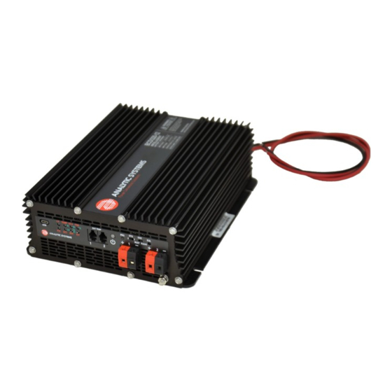
Main Parts Front Panel Power Button End-of-Charge Switch USB Communications Port Equalize Start Button Indicator LED Display Stage Select Switch Battery Temperature Sensor Battery Output Connection: 2x Connection Ports Phoenix VDFK Terminal Block Connetions (Red: Positive, Black Negative) Program Button 10. -
Page 7: Operation
Temperature, Battery Over-Temperature, Low Input Voltage, Input Power Failure and more. In addition to being a battery charger, the BCDi320 is also capable of functioning as a power supply. While in Power Supply Mode, the unit’s functionality is changed in the following ways: •... -
Page 8: Power Supply Mode
POWER SUPPLY MODE Connect the unit to the DC power source and batteries being charged. Press the Power Button on the unit’s front panel. The battery charger will go through its startup sequence. All 6 microprocessor-controlled LEDs flash red and then green. When the Power Button starts glowing, the sequence is complete. -
Page 9: Installation
Do not connect or disconnect anything to the unit while it is powered. To reduce the risk of high voltage electric shock, never connect or disconnect anything to the BCDi320 while it is ON. INPUT POWER CONNECTION The unit is equipped with two 3-foot/1 meter Type D Stranded AWG14 wire leads to serve as a DC Input Connection. -
Page 10: Dc Output Connection
DC OUTPUT CONNECTION This unit is equipped with a pair of Phoenix VDFK Terminal block connectors to serve as a DC Output connection for connection to battery banks. The connection can support up to two connected battery banks. The polarity for these connections can be found on the unit’s front panel label. CAUTION: If you are charging two banks of batteries, they MUST share a common ground! Connector Color... -
Page 11: Connection Indicators
Connection CONNECTION INDICATORS 1. Connect the charger to the batteries as indicated under Installation. TEMP LO V 2. Check the POL LED on the front panel. If it is glow- ing red, the battery is connected in reverse polarity. Correct the connection to the battery (The red terminal should go to Positive and black to Negative). -
Page 12: Battery Type
BATTERY TYPE BATTERY TYPE INDICATORS The Battery Type parameters controls the type of charging profile that the LO V unit will use to charge the battery. TEMP LO V TEMP Different types of batteries have different optimal charging voltages and currents due to their construc- tion and chemical composition. -
Page 13: Saving And Exiting
DEFAULT BATTERY TEMPERATURE DEFAULT BATTERY The Default Battery Temperature TEMPERATURE INDICATORS parameters controls the charger’s estimated value of the battery TEMP LO V TEMP LO V temperature. The optimal charging voltage of a battery will decrease as its temperature increases. The charger uses this value to calculate DEFAULT WARM (21°C/70°F) its charging compensation if there... -
Page 14: Front Panel Adjustments
Front Panel Adjustments Using the two switches between the Program and Select buttons on the front panel, you can select whether a 2-stage or 3-stage charging profile is used to charge the batteries and control the battery charger’s behavior when the charging cycle ends. END-OF-CHARGE SELECT The End-of-Charge (EOC) select switch controls the charger’s behavior after it finishes charg- ing the battery/ batteries. -
Page 15: Charging Profiles
Charging Profiles This unit has both two-stage and three-stage charging capability. You can choose which charg- ing profile is used during operation by using the Stage Select switch on the front panel. Below are explanations of the two profiles: TWO-STAGE CHARGING Bulk Float •... - Page 16 Equalize Cycle If a battery’s cells are left discharged for too long, sulfate crystals can form on the plates interfer- ing with their conductance. This reduces the battery’s capacity and recharging ability. An equalize cycle is a deliberate overcharge of the battery at high voltage (110% of float voltage) and low current (10% of standard output) to force undercharged cells to match charge of the good cells in the battery.
-
Page 17: Battery Temperature Sensor
Pictured: An Analytic Systems Battery Temperature Sensor (B-TEMP) BATTERY TEMPERATURE SENSOR CONNECTION This unit is equipped with 2 RJ45 Telephone Jack connector to connect to up to two Analytic Systems battery temperature sensor(s). -
Page 18: Maintenance
Normally Closed contact. Digital Meter - Option V The BCDi320 can be equipped (by factory order) with a bright chassis-integrated digital meter to display the battery voltage and charging current being supplied to up to both connected... -
Page 19: Troubleshooting
Troubleshooting The BCDi320 is designed to provide years of reliable service and to auto-recover in the event of an operational failure. In the event of malfunction, the unit is fitted with eight LED indica- tors and an audible alarm to help diagnose the cause of the issue. Below is a list of potential issues, and how to repair them. -
Page 20: Battery Failed
FAULT INDICATORS BLINKING Charger Failure Indication TEMP LO V The microprocessor has detected a condition that prevents the charger from operating. Try disconnecting the Input power and re-connecting it. If this does not clear the fault, the cause is likely an internal component failure and the charger will have to be returned for service CHARGER FAILED Battery Fail Indication... - Page 21 Glossary We use a number of abbreviations on the labels to save space. Here are the full words corre- sponding to each abbreviation along with common battery charger terms and their definitions: ABBREVIATIONS POL – Polarity. Refers to the correct connection of the Positive and Negative terminals of the battery to the charger.
-
Page 22: Specifications
Specifications Input Volts (VDC) 100-350 VDC Current (max) * 4 Amps w. Inrush Protection Input Fuse 6.3A 400 VDC Power Factor > 0.99 at Full Load Efficiency > 90% at Full Load *Maximum Input Current Specified at 85 VAC Output Nominal Voltage 12 VDC 24 VDC... -
Page 23: Limited Warranty
2 Years from date of manufacture for non-standard or OEM products 1 Year from date of manufacture for encapsulated products. 3. Analytic Systems will determine eligibility for warranty from the date of purchase shown on the warranty card when returned within 30 days, or... - Page 24 DESIGNED AND MANUFACTURED BY 800-668-3884 604-946-9983 sales@analyticsystems.com www.AnalyticSystems.com Battery Chargers • Inverters • Power Supplies • Voltage Converters 8128 River Way Delta, BC V4G 1K5 | Canada Register Products Online | www.analyticsystems.com/support/warranty-registration...
Need help?
Do you have a question about the BCDi320 and is the answer not in the manual?
Questions and answers