Table of Contents
Advertisement
Quick Links
Parallel Line Driver—T
Parallel Line Driver—R
CUSTOMER
SUPPORT
INFORMATION
Order toll-free in the U.S. 24 hours, 7 A.M. Monday to midnight Friday: 877-877-BBOX
FREE technical support, 24 hours a day, 7 days a week: Call 724-746-5500 or fax 724-746-0746
Mail order: Black Box Corporation, 1000 Park Drive, Lawrence, PA 15055-1018
Web site: www.blackbox.com • E-mail: info@blackbox.com
APRIL 1995
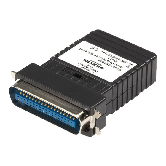
ME190A
ME191A
ME192A
ME193A
Advertisement
Table of Contents

Subscribe to Our Youtube Channel
Related Manuals for Black Box ME190A


Summary of Contents for Black Box ME190A
- Page 1 Order toll-free in the U.S. 24 hours, 7 A.M. Monday to midnight Friday: 877-877-BBOX SUPPORT FREE technical support, 24 hours a day, 7 days a week: Call 724-746-5500 or fax 724-746-0746 INFORMATION Mail order: Black Box Corporation, 1000 Park Drive, Lawrence, PA 15055-1018 Web site: www.blackbox.com • E-mail: info@blackbox.com...
- Page 2 PARALLEL LINE DRIVER FEDERAL COMMUNICATIONS COMMISSION INDUSTRY CANADA RADIO FREQUENCY INTERFERENCE STATEMENTS This equipment generates, uses, and can radiate radio frequency energy and if not installed and used properly, that is, in strict accordance with the manufacturer’s instructions, may cause interference to radio communication. It has been tested and found to comply with the limits for a Class A computing device in accordance with the specifications in Subpart J of Part 15 of FCC rules, which are designed to provide reasonable protection...
- Page 3 PARALLEL LINE DRIVER NORMAS OFICIALES MEXICANAS (NOM) ELECTRICAL SAFETY STATEMENT INSTRUCCIONES DE SEGURIDAD 1. Todas las instrucciones de seguridad y operación deberán ser leídas antes de que el aparato eléctrico sea operado. 2. Las instrucciones de seguridad y operación deberán ser guardadas para referencia futura.
- Page 4 PARALLEL LINE DRIVER 11. El aparato eléctrico deberá ser connectado a una fuente de poder sólo del tipo descrito en el instructivo de operación, o como se indique en el aparato. 12. Precaución debe ser tomada de tal manera que la tierra fisica y la polarización del equipo no sea eliminada.
- Page 5 PARALLEL LINE DRIVER TRADEMARKS Centronics ® is a registered trademark of GENICOM Corporation. AT&T ® is a registered trademark of AT&T. Any other trademarks mentioned in this manual are acknowledged to be the property of the trademark owners.
-
Page 6: Table Of Contents
PARALLEL LINE DRIVER Contents Chapter Page 1. Specifications ....................6 2. Introduction......................7 2.1 Description ....................7 2.2 Features ....................7 3. Configuration....................8 4. Installation ......................10 4.1 Connecting the Line Side..............10 4.1.1 Terminal-Block Connection ............10 4.1.2 RJ-11 Line Connection ..............16 4.2 Connecting to Parallel Hardware ............17 4.3 Operating the Parallel Line Driver ............17 Appendix A: Parallel Pin Configurations ............18 Appendix B: Block Diagrams ................20... -
Page 7: Specifications
PARALLEL LINE DRIVER 1. Specifications Data Rate — 5 Kilobytes per second Parallel Interface — on parallel interface (40 Kbps ME190A: transmitter, DB25 on serial line) male w/terminal block, ME191A: receiver, Centronics Interface Signals — Data bits 0-7, male w/terminal block,... -
Page 8: Introduction
CHAPTER 2: Introduction 2. Introduction 2.1 Description 2.2 Features The Parallel Line Driver allows • Extends parallel communication a PC and a parallel output device to 2000 feet (609.6 m) (printer, sharing switch, etc.) to communicate at distances to • Requires no AC power or 2000 feet (609.6 m) over a single batteries unconditioned twisted pair. -
Page 9: Configuration
PARALLEL LINE DRIVER 3. Configuration The Parallel Line Driver is designed to be easy to use. There are no internal jumpers or DIP switches to set, so there is no need to open the case to configure the unit (you may need to open the case for wire connection—refer to Chapter 4). - Page 10 CHAPTER 3: Configuration Setting the Busy/Acknowledge Switch There are three things to keep in mind when you set the BUSY/ ACKNOWLEDGE switch (see Figure 3-2): Busy Figure 3-2. BUSY/ACKNOWLEDGE Switch. 1. The switch must be set the same way on both transmitter and receiver.
-
Page 11: Installation
PARALLEL LINE DRIVER 4. Installation 4.1.1 T Once you have configured the ERMINAL LOCK ONNECTION Parallel Line Driver transmitter Terminal blocks are used to connect and receiver, you must connect a single pair of bare wires to the the system. This section will tell you Parallel Line Driver. - Page 12 CHAPTER 4: Installation After you have opened the unit’s case, you will find the terminal block mounted at the rear of the PC board. The terminals are labeled “S” for signal and “G” for ground. 2. Strip the outer insulation from the twisted pairs about one inch from the end.
- Page 13 PARALLEL LINE DRIVER 4. Insert the two-wire data line to the center (signal) and shield (ground) terminal posts, then tighten the screws. Figure 4-4. Inserting the Two-Wire Data Line. NOTE Make sure the twisted pair cable between the trans- mitter and receiver is wired straight through as shown in Figure 4-5.
- Page 14 CHAPTER 4: Installation 5. Place the two halves of the strain-relief assembly on either side of the telephone wire and press together very lightly. Slide the assembly so that it is about two inches from the terminal posts and press together firmly. Figure 4-6.
- Page 15 PARALLEL LINE DRIVER 6. Insert the strain-relief assembly and the wire into the slot in the bottom half of the modem case. Set it into the recess in the case. If the telephone wire does not fit into the strain-relief assembly, call for technical support.
- Page 16 CHAPTER 4: Installation 7. Bend the top half of the case as necessary to place it over the strain-relief assembly. Do not snap the case together yet. Figure 4-8. Placing the Case over the Strain-Relief Assembly. 8. Insert one captive screw through a saddle washer and then insert the entire piece through the hole in the DB25 end of the...
-
Page 17: Line Connection
PARALLEL LINE DRIVER 4.1.2 RJ-11 L ONNECTION When using the RJ-11 modular jacks, install straight-through cabling between the transmitter and receiver, as shown below: Table 4-1. RJ-11 Jacks. Signal Pin # Color Color Pin # Signal DATA Green ——Green DATA Red ————Red Standard AT&T ®... -
Page 18: Connecting To Parallel Hardware
CHAPTER 4: Installation 4.2 Connecting to Parallel Hardware NOTE If you cannot plug the After connecting the twisted-pair receiver directly into the port, line to the Parallel Line Driver use a straight through cable transmitter and receiver, you are of the shortest possible ready to connect the units to your length. -
Page 19: Appendix A: Parallel Pin Configurations
PARALLEL LINE DRIVER Appendix A: Parallel Pin Configurations TRANSMITTER (DB25) SOURCE TRANSMITTER / RECEIVER (DB-25) SOURCE 13 - Select (Active HIGH) Printer Common Return / Ground - 25 12 - Paper End (Active HIGH) Printer Common Return / Ground - 24 11 - Busy (Active HIGH) Printer Common... - Page 20 APPENDIX A: Parallel Pin Configuration DIRECTION RECEIVER (CENTRONICS) DIRECTION Printer - 36 18 - (+) 5 Volts Common - 35 17 - Chassis Ground Common - 34 16 - Logic Ground - 33 15 - Printer 14 - Fault (Active LOW) - 32 Printer - 31 13 - Select (Active HIGH)
-
Page 21: Appendix B: Block Diagrams
PARALLEL LINE DRIVER Appendix B: Block Diagrams GATED STROBE OSCILLATOR RJ11 CONNECTOR PARALLEL PULSE TRANSFORMER WIDTH SERIAL MODULATOR CONVERSION (TO RECEIVER) CONTROL BUSY CIRCUITRY DATA STROBE POWER SELECT SUPPLY L FEED INI PRN Figure B-1. Block Diagram (Transmitter). - Page 22 APPENDIX B: Block Diagrams CONTROL STROBE CIRCUITS RJ11 CONNECTOR SERIAL DIFFERENTIAL TRANSFORMER PARALLEL RECEIVER CONVERSION (TO TRANSMITTER) CONTROL BUSY CIRCUITRY SWITCH BUSY P OUT POWER SUPPLY FAULT Figure B-2. Block Diagram (Centronics Receiver).
- Page 23 © Copyright 1995. Black Box Corporation. All rights reserved. 1000 Park Drive • Lawrence, PA 15055-1018 • 724-746-5500 • Fax 724-746-0746...
Need help?
Do you have a question about the ME190A and is the answer not in the manual?
Questions and answers