Table of Contents
Advertisement
Quick Links
Advertisement
Table of Contents

Related Manuals for Fluke 8588A


Summary of Contents for Fluke 8588A
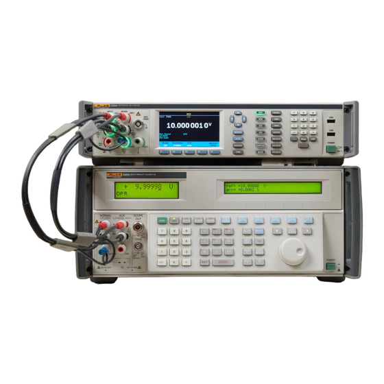
- Page 1 8588A/8558A Reference Multimeter and 8 1/2 Digit Multimeter Operators Manual February 2019 © 2019 Fluke Corporation. All rights reserved. Specifications are subject to change without notice. All product names are trademarks of their respective companies.
- Page 2 Fluke authorized resellers shall extend this warranty on new and unused products to end-user customers only but have no authority to extend a greater or different warranty on behalf of Fluke. Warranty support is available only if product is purchased through a Fluke authorized sales outlet or Buyer has paid the applicable international price.
-
Page 3: Table Of Contents
Contact Fluke Calibration ..............2 Service Information ................2 Product Features ................... 3 Common Features ................3 8588A Reference Multimeter ............. 4 8558A 8 1/2 Digit Multimeter ............. 4 Installation ..................... 4 Unpack and Inspect the Product ............4 Standard Equipment ................5 Placement and Rack Mounting.............. - Page 4 Set the Measurement Frequency ..........54 Frequency Counter ................55 Measure Frequency ................58 DCI Ext Shunt (8588A Only) .............. 59 ACI Ext Shunt (8588A Only) .............. 62 Measure AC Current with ACI Ext Shunt ........... 68 PRT ....................69 Measure PRTs ...................
-
Page 5: Introduction
Introduction The Fluke Calibration 8558A 8 1/2 Digit Multimeter and 8588A Reference Multimeter (the Product or Multimeter unless otherwise specified) are for demanding and precise measurement applications. The Product functions in both stand-alone and systems applications. 8 1/2 digit resolution provides high performance and makes the Product well suited for application use in standards labs, calibration labs, engineering labs, and systems use. -
Page 6: Instruction Manuals
Fluke Calibration Service Department) To order, see the Fluke Calibration Catalog or contact a Fluke Calibration sales representative. See Contact Fluke Calibration. This manual provides complete information to install and operate the Product from the front panel. -
Page 7: Product Features
Reference Multimeter and 8 ½ Digit Multimeter Product Features Product Features Common Features The Products share a common chassis and display/hardware platform. They are differentiated by additional precision components and firmware. The Product shares these capabilities: • Inherent accuracy and stability without the need for periodic internal automatic adjustments like the ACAL function •... -
Page 8: 8588A Reference Multimeter
The 8588A has specifications suited for the most demanding calibration and metrology applications. 8558A 8 1/2 Digit Multimeter The 8558A specifications are relaxed from those of the 8588A but its specifications are comparable to other 8 1/2 digit multimeters. Installation... -
Page 9: Standard Equipment
Fluke Calibration Part Number 8588A Reference Multimeter 4983182 8558A 8 ½ Digit Multimeter 4983194 See Mains Voltage Mains Power Cord 8558A/8588A Safety Information (printed) 4769456 8588A-LEAD KIT-OSP 4951331 General Purpose Probe Kit & Pouch Calibration Certificate Placement and Rack Mounting Put the Product on top of a workbench or mount the Product in a standard 48-cm (19-inch) wide, 61-cm (24-inch) deep equipment rack. -
Page 10: Cooling Considerations
8588A/8558A Operators Manual Cooling Considerations WCaution Damage caused by overheating can occur if the area around the air intake or exhaust exit is restricted, the intake air is too warm, or the air filter becomes clogged. An important feature of the Product is its internal cooling system. Baffles direct cool air from the fans throughout the chassis to dissipate heat during operation. -
Page 11: Mains Voltage
The Product comes with the appropriate line power plug for the country of purchase. If a different type is necessary, see Table 2. They list and show the mains line power plug types available from Fluke Calibration. The Product automatically detects the main line voltage when powered up and configures itself to work at that voltage level. -
Page 12: Grounding The Product
North American/Japan Universal Euro United Kingdom LC-3 LC-1 LC-4 LC-5 Australia/China South Africa Brazil LC-6 LC-7 LC-42 hwr039.emf Type Fluke Calibration Option Number North America 284174 Universal Euro 769422 United Kingdom 769455 Switzerland 769448 Australia 658641 South Africa 722771 Brazil 3841347... -
Page 13: Line Power And Fuse
This section provides descriptions of each panel feature. Read this information before Product use. Front-panel operation instructions for the Product are in Front-Panel Operation. Remote operations instructions are in Remote Programmer’s Manual. Features that are unique to either the 8588A or 8558A are noted as such. -
Page 14: Front-Panel Features
Function A pair of five-way binding posts for current measurements. Signals INPUT Terminals up to 30 A rms can be applied to these terminals on the 8588A and A, HI, and LO up to 2 A on the 8558A.These terminals illuminate to show connections. - Page 15 When pushed, makes other functions visible that can be selected in the Product: Capacitance (8588A only), RF Power (8588A only), Frequency Counter, DCI Ext Shunt (8588A only), ACI Ext Shunt (8588A only), PRT readout, and Thermocouple readout. This key is ...
- Page 16 8588A/8558A Operators Manual Table 3. Front-Panel Features (cont.) Number Name Function Starts a process that corrects for analog offset errors in an entire function, or for a specific range. See Zero. Numbered keys to enter various Product parameters and other data ...
- Page 17 Reference Multimeter and 8 ½ Digit Multimeter Front and Rear Panel Table 3. Front-Panel Features (cont.) Number Name Function Triggers a measurement when the Product is in the non-continuous trigger (idle) state. The idle state occurs when the Run/Stop key is ...
-
Page 18: Rear-Panel Features
2 A rms can be applied to these terminals. A pair of five-way binding posts for voltage, ohms, capacitance, 2- wire PRT, and thermocouple measurements. On the 8588A, these INPUT, V HI and binding posts also connect to the output of external current shunts. - Page 19 Reference Multimeter and 8 ½ Digit Multimeter Front and Rear Panel Table 4. Rear-Panel Features (cont.) Number Name Function Holds the fuse that is in series with the rear Input A Hi input. F1.6AH Fuse holder 250 V fuse protects the current-measuring circuity when using the rear terminals for signal input.
-
Page 20: Operation
During the power-up process, the Product goes through a series of self- tests. If a self-test fails, a prompt on the display identifies the failed test and prevents further operation. If the test fails, contact Fluke Calibration. Power-Up State After passing the power-up self-tests, the Product goes into the power-up state. -
Page 21: Warmup Requirements
Reference Multimeter and 8 ½ Digit Multimeter Operation Table 5 summarizes the non-volatile setup parameters and their factory defaults. Table 5. Non-volatile Setup Parameter Factory Defaults Factory Default Setup Parameter (Value after Non-Volatile Memory Format) Remote Port GPIB IEEE-488 Bus (GPIB) Address Real Time Clock Date Not changed Real Time Clock Time... -
Page 22: Functions
8588A/8558A Operators Manual Functions The subsequent sections explain the different functions of the Product. DC Voltage The DC Voltage function provides 2-wire measurements using the V INPUT HI and LO Input terminals. Push to use the DC Voltage (DCV) function. -
Page 23: Measure Dc Voltage
Use a twisted-pair to reduce the loop area and adjacent twists will cancel any induced voltages. If you encounter problems with stray pick-up, Fluke Calibration recommends that you use a shielded twisted-pair cable with the screen connected to the INPUT LO terminal at the source as shown in Figure 3. -
Page 24: Common Mode Rejection - Use Of External Guard Connection
8588A/8558A Operators Manual Common Mode Rejection - Use of External Guard Connection When the source presents an unbalanced impedance to the measuring terminals, and common mode voltages are present, use the GUARD terminal with External Guard selected. Use and then (Ext. Guard) to activate the GUARD terminal. - Page 25 Reference Multimeter and 8 ½ Digit Multimeter Functions AC Voltage Menu This section explains the AC Voltage (ACV) menu. See the screen below. iei005.png (Range): Select each of the ac V ranges manually or select Auto to put the Product into Autorange. Make the range selection with the softkeys or use the navigational keys to highlight the selection and push .
- Page 26 8588A/8558A Operators Manual (RMS Filter): Push to select various filters for the rms converter, allowing measurements down to the chosen filter frequency without degradation of accuracy and excessive reading variation. One of the filters is always in circuit. The 40 Hz filter is the default selection at power on. The filter choices available are 0.1 Hz, 1 Hz, 10 Hz, 40 Hz, 100 Hz and 1 kHz.
- Page 27 Reference Multimeter and 8 ½ Digit Multimeter Functions • Secondary reading: The ACV function can show a secondary reading. The choices are: o (OFF) (none) o (Frequency) o (Period) o (Pk to Pk) o (More) o ...
-
Page 28: Measure Ac Voltage
Triangle is 2 x (square root of 3) x rms, and Truncated Sine is 4.618803 x rms. Use the Square, Triangle and Truncated Sine selections to measure the peak-to-peak output of multi-product calibrators like the Fluke 5522A which have these non-sine wave outputs. -
Page 29: Dc Current
Auto. The ranges available are 10 µA to 30 A for the 8588A and up to 1 A (202 % overrange) for the 8558A. Resolutions vary from 7 1/2 digits to 4 1/2 digits. 10 µA to 10 A ranges provide 202 % overrange. - Page 30 8588A/8558A Operators Manual Measure DC Current The Product measures current with the INPUT A and INPUT LO terminals. The current should flow from the source’s high terminal into the multimeter A terminal and back to the source’s low terminal out of the multimeter LO terminal.
-
Page 31: Ac Current
The AC Current function features 8 ranges (10 μA to 30 A) for the 8588A and 6 ranges (10 μA to 1 A) for the 8558A. The 10 µA, 100 µA, 1 mA, 10 mA, 100 mA and 10 A, ranges provide 202 % overrange. For example, the 10 A range displays up to 20.2 A. -
Page 32: Aci Measure Setup
8588A/8558A Operators Manual (Measure Setup): The Measure Setup softkey in ACI menu has parameters that can be set up to make ac current measurements. Parameter choices are: • Signal path coupling • Secondary Reading • Frequency path coupling •... - Page 33 Reference Multimeter and 8 ½ Digit Multimeter Functions • Frequency path coupling: The frequency path coupling can be AC or DC if the Signal path coupling, impedance (above) is set to any of the dc settings. Otherwise, only ac is available and this submenu is not operational. •...
-
Page 34: Measure Ac Current
Truncated Sine is 4.618803 x rms The Square, Triangle and Truncated Sine selections are useful to measure the peak-to-peak output of multi-product calibrators like the Fluke 5522A which have these non-sine wave outputs. Measure AC Current The Product measures ac current with its INPUT A and INPUT terminals. -
Page 35: Resistance
Reference Multimeter and 8 ½ Digit Multimeter Functions Note The current path between the Product terminals is not made when the current functions are not in use or when front or rear terminals are deselected. The rear input terminals may be used to measure currents up to 2 A only. - Page 36 8588A/8558A Operators Manual Note With LoI ON, the behavior of auto ranging is modified such that the Ω Ω Product will not auto range up from the 10 k to 100 k range, nor from the 100 M Ω to 1 G Ω...
- Page 37 Reference Multimeter and 8 ½ Digit Multimeter Functions Note The pole or time constant of the filter is formed by a 22 nF capacitor across the resistance under test. Note The selected range and resolution are remembered across Normal, Tru ohm, and HV modes. For example, if Auto and 8 Digits are set in 2W Normal, they are also set in 4W Normal.
- Page 38 8588A/8558A Operators Manual • 2W HV Ω: This mode provides 2-wire measurements of resistance, in decade ranges from 10 MΩ to 10 GΩ. The measurement is performed at High Voltage using a current source with high compliance. The resulting increase in current through the unknown resistor reduces uncertainties due to leakage and bias current.
- Page 39 Reference Multimeter and 8 ½ Digit Multimeter Functions Current stimulus values are shown in Table 9 for each of the five resistance modes. Table 9. Ohms Stimulus Levels for Each Mode 2W and 4W Tru Ω LoI 2W and 4W Normal 4W Tru 2W and 4W...
-
Page 40: Measure Resistance
8588A/8558A Operators Manual Measure Resistance 2-Wire Measurements For many applications the simple 2-wire arrangement will be adequate. See Figure 5. However, the value shown includes the resistance of the connecting leads. Use a shielded twisted-pair cable, preferably of PTFE insulation, to reduce induced voltages, induced charge and shunt leakage resistance, particularly where Rx is high. -
Page 41: 4-Wire High-Resistance Measurements
Reference Multimeter and 8 ½ Digit Multimeter Functions 4-Wire High-Resistance Measurements When you make very high resistance measurements (above approximately 1 MΩ) a metal screen can be wrapped around the resistor to reduce noise, usually caused by charge injection. Connect the GUARD terminal to the screen to intercept leakage with the screen (in parallel with the unknown resistor). -
Page 42: Ω Guard
8588A/8558A Operators Manual Ω Guard In the Resistance function, with Ext. Guard selected (see also Input Terminal Selection), the GUARD terminal functions as an Ω Guard. Use the GUARD terminal as Ω Guard and the Ω Guard feature can make ‘in-circuit’ resistance measurements by guarding out parallel resistance paths. -
Page 43: Digitize
Reference Multimeter and 8 ½ Digit Multimeter Functions Example: If Rd = 100 Ω, Rg = 1 Ω, Ra = Rb = 10 kΩ, then the value of E is given by: E = (100 x 1) / (10 k x 10 k) = 10 (1 ppm of readings) The value of Rx is thus given by: Rx = 100 x (1 + 10... - Page 44 8588A/8558A Operators Manual Note Data acquisition in Digitize starts from the front panel when you push or by a remote command. You cannot start an acquisition with . is normally used to toggle the Trigger subsystem from the free-run state (Initiate Continuous ON) to the idle state (Initiate Continuous OFF).
- Page 45 Reference Multimeter and 8 ½ Digit Multimeter Functions iei190.png This figure shows a changing signal level (0.5 μV to 1.9 μV) vs time. If the Aperture is set to 0 ns, the sample value is 0.5 μV and the sample was captured at the time of the trigger. If the Aperture is set to 200 ns, the sample value is (0.5 μV + 0.9 μV)/2 or 0.7 μV, which is 200/2 or 100 ns after the trigger.
- Page 46 100 mV, 1 V, 10 V, 100 V, and 1 kV. Current ranges are 10 μA, 100 μA, 1 mA, 10 mA, 100 mA, 1 A, 10 A, and 30 A (8588A only) from the front inputs. If the rear inputs are used, the 10 A and 30 A ranges are not available.
- Page 47 Reference Multimeter and 8 ½ Digit Multimeter Functions (Measure Setup): A 100 kHz or 3 MHz low pass filter or Filter Off can be selected and the aperture is set in this setup menu. The low pass filter is inserted after the signal conditioning and before the high-speed analog-to-digital converter.
- Page 48 8588A/8558A Operators Manual Table 11. Digitize Example 2 Action Comment Aborts any current trigger cycle. Trigger Push subsystem placed in the Idle state, INIT:CONT OFF. If not already in voltage mode, push (V or I) to select Voltage.
- Page 49 Reference Multimeter and 8 ½ Digit Multimeter Functions Table 11. Digitize Example 2 (cont.) Action Comment Use the navigation keys and push to set the first row, trigger event, to Timer. Push to return to the top of the Trigger Setup menu and ensure that the Trigger Event is set to Timer.
- Page 50 8588A/8558A Operators Manual 3) Capture 4096 samples of a 1 Vrms, 4 kHz wave form with a 5 μs acquisition period and at a rate controlled by an external 10 kHz trigger wave form. See Table 12. Table 12. Digitize Example 3...
- Page 51 Reference Multimeter and 8 ½ Digit Multimeter Functions Table 12. Digitize Example 3 (cont.) Action Comment Check that the second row shows the type and polarity of trigger edge required. If not, highlight Default is TTL, Negative. row two and push to change the settings. The Trigger subsystem Arm 2 and Arm1 layer trigger events are automatically satisfied since Push ...
-
Page 52: More
After you push (More), DCI Ext Shunt is made available by . Push (More) additional times to cycle the choices again starting with (Capacitance). Capacitance (8588A only) WCaution To avoid possible damage to the Product or to the equipment under test, disconnect circuit power and discharge all high- voltage capacitors before you measure capacitance. - Page 53 C = I dV/dt. One use for the Capacitance function is to measure the output of multi-function calibrators, for example the Fluke 5522A. Connect the Product INPUT HI to the calibrator OUTPUT HI and the Product INPUT LO to the calibrator OUTPUT LO.
-
Page 54: Rf Power (8588A Only)
Even brief overloads can destroy the sensor. WCaution The Product front-panel Power Sensor connector interface is only for use with compatible power sensors. To prevent damage to the Product, no other connection is permitted. Fluke Calibration supplies a NRP type sensor as an option. - Page 55 Reference Multimeter and 8 ½ Digit Multimeter More RF Power Menu Push and then (RF Power) to enable the RF Power function. If a RF sensor is not connected, a connection message at the bottom of the screen prompts you to do so. This section explains the RF Power menu. See the screen below: iei034.png When a compatible sensor is plugged into EXT PORT, the top of the RF Power...
-
Page 56: Rf Power Softkeys
8588A/8558A Operators Manual Table 13. Setting Limits for Reference Level Units Parameter Watts 100.03 fW 9.9997 MW Vrms 2.2364 μV rms 22.358 kVrms Vpk-pk 6.326 μVpk-pk 63.24 kVpk-pk dBμV -6.991 dBμV 206.988 dBV RF Power Softkeys This section explains the RF Power softkeys. -
Page 57: Connect A Power Sensor To The Product
Reference Multimeter and 8 ½ Digit Multimeter More Connect a Power Sensor to the Product To connect the power sensor interface cable multiway connector to the Product: 1. Remove the plastic cap from the cable-end connector and save it for future use. -
Page 58: Connect A Power Sensor To A Unit Under Test
8588A/8558A Operators Manual Connect a Power Sensor to a Unit Under Test WCaution To prevent damage to the Product: • Never exceed the maximum RF power limit. Even brief overloads can destroy the sensor. See Specifications. • Do not touch the RF connector inner conductor. The power sensor contains components which can be destroyed by electrostatic discharges. -
Page 59: Frequency Counter
Reference Multimeter and 8 ½ Digit Multimeter More Frequency Counter From the More menu, push (Frequency) to use the Frequency Counter measuring function. The Frequency Counter measuring function defaults to using the rear panel BNC connector to make frequency measurements. The input is selected using ... - Page 60 8588A/8558A Operators Manual Table 14. Equivalent Resolution/Gate Setting Counter Display Resolution Counter Gate 8 digits 7 digits 100 ms 6 digits 10 ms 5 digits 1 ms 100 μs 4 digits (Parameter): Allows display of either frequency (default) or period.
- Page 61 Reference Multimeter and 8 ½ Digit Multimeter More Threshold: Can be set to -5 V to +5 V with 0.1 V setting resolution when the BNC input is selected. Default is 0.0 V. Input path: Use to select the frequency counter input path. The choices are: ...
-
Page 62: Measure Frequency
8588A/8558A Operators Manual Measure Frequency When Frequency is measured with the rear BNC connector, use shielded coaxial leads. See Figure 16. iei341.jpg Figure 16. Frequency Measurement with Rear Input When measuring frequency using the V INPUT HI and LO terminals, use the same leads that you use in ACV. -
Page 63: Dci Ext Shunt (8588A Only)
Reference Multimeter and 8 ½ Digit Multimeter More DCI Ext Shunt (8588A Only) The DCI Ext Shunt function measures the dc voltage across the shunt and shows the calculated current, taking into account specific characteristics of the external shunt. Push then (DCI Ext Shunt) to use the DCI Ext Shunt function. - Page 64 8588A/8558A Operators Manual (Measure Setup): Aperture/PLC sets the integration time of the A to D converter using the navigational keys, much like Measure Setup in DCV. The choices are: • Auto • Auto Fast • Manual When you select Manual, use the softkeys and the numerical keypad to edit the integration time by PLC and Time.
- Page 65 Reference Multimeter and 8 ½ Digit Multimeter More • Maximum current: Use the numeric keypad and to input the maximum current that can be applied to the shunt without causing a resistance value change. Maximum current is displayed as the third field in the shunt information line.
-
Page 66: Aci Ext Shunt (8588A Only)
F M iei105.emf Figure 17. External DC Shunt Connection ACI Ext Shunt (8588A Only) The ACI Ext Shunt function measures the ac voltage across the shunt and shows the calculated current, taking into account specific characteristics of the external shunt. - Page 67 Ext Shunt submenu mentioned previously. Push (Edit AC-DC Differences) to open a menu to enter ac-dc differences of the current shunt. When using Fluke A40B current shunts, enter the ac-dc differences at each of the frequency points from the calibration certificate of the respective shunt.
- Page 68 8588A/8558A Operators Manual Enter the appropriate information for each of the fields listed with the navigation keys and numeric keypad. • Asset number (shown as the first field on the shunt information line of the main DCI Ext Shunt screen) •...
- Page 69 Reference Multimeter and 8 ½ Digit Multimeter More ACI Ext Shunt Measure Setup Menu The section explains the ACI Ext Shunt (Measure Setup) menu submenu. • Signal path coupling: Choose (AC) or (DC). • Secondary Reading: In the ACI function, a secondary reading can be shown.
- Page 70 8588A/8558A Operators Manual • Frequency path bandwidth limit: Choose (OFF) or (ON). Reduces noise in the frequency counter signal path. If there is excessive noise observed, turn the bandwidth limit ON for signals <70 kHz. • Counter Gate: Set to: o ...
- Page 71 Reference Multimeter and 8 ½ Digit Multimeter More The Square, Triangle, and Truncated Sine selections are useful to measure the peak-to-peak output of multi-product calibrators like the Fluke 5522A which have these non-sine wave outputs. See the screen below: iei017.png...
-
Page 72: Measure Ac Current With Aci Ext Shunt
The ACI Ext Shunt function provides a calculated current reading for a specified current shunt. The ACI Ext Shunt function is particularly useful for current shunts that have corrections for ac-dc differences at different frequencies, like the Fluke A40B series current shunts. Connections are shown in Figure 18. -
Page 73: Prt
Reference Multimeter and 8 ½ Digit Multimeter More Push , (More), then (PRT) (platinum resistance thermometer) to use the PRT measure function. The PRT measure function provides a temperature readout by measuring the resistance of a connected PRT. 2 Wire, 3 Wire, or 4 Wire measurements can be made. PRT Submenu This section explains the PRT submenu. - Page 74 Connect the PRT probe to the Product in the same way as when making resistance measurements, using the appropriate connection shown in Figure 19. Select the corresponding 2-, 3-, or 4-wire probe type using the (Probe) softkey. Fluke Calibration recommends that Ext. Guard is ON (, (Ext. Guard)). adj131f.emf Figure 19.
-
Page 75: Thermocouple
The Thermocouple function can be used to calibrate actual thermocouples themselves or to calibrate the electronic thermocouple output of thermocouple simulators like those found in the Fluke 5522A Multi-Product Calibrator. Both of these applications require the use of an external reference junction, often referred to as the cold temperature junction. - Page 76 Using a commercially-available zero-point dry-well as the cold junction, Figure 21 shows the connections required between the Product and the DUT, an electronic simulator in the Fluke 5522A. iei338.jpg Figure 21. Thermocouple Connection...
- Page 77 Reference Multimeter and 8 ½ Digit Multimeter Thermocouple In this example, the Fluke 5522A simulator and the Product are both set to a J- type thermocouple (constantan and iron). You must use the correct J-type hookup wire and connector between the DUT and the cold junction. The connection from the cold junction to the Product must be with copper wire.
-
Page 78: Features
8588A/8558A Operators Manual Features Input Terminal Selection The Product has front and rear INPUT terminals. Push within any function to open the various input configurations. Softkeys to configure the terminals. XWWarning To prevent possible electrical shock, fire, or personal injury, do not apply more than the rated voltage, between the terminals or between each terminal and earth ground. -
Page 79: Use The Scan Operations
Reference Multimeter and 8 ½ Digit Multimeter Features The delay setting and resolution is shown in Table 16. Table 16. Delay Settings and Resolution Delay Setting Resolution <1 s 1 ms 1 s to 10 s 10 ms 10 s to 65 000 s 100 ms 1. -
Page 80: Scan Sequences
(Front - Rear, Front / Rear, and (Front - Rear) / Rear) are configured uniquely in a mode Fluke Calibration calls Tru Ohm Ratio, a feature also found in the Fluke 8508A Reference Multimeter. The Product applies a stimulus current of... - Page 81 Reference Multimeter and 8 ½ Digit Multimeter Features INPUT HI SENSE HI Front Input SENSE LO INPUT LO Stimulus Current Source (Reversing) Potential Difference Mea surement INPUT HI SENSE HI Rear Input SENSE LO INPUT LO adj132f.emf Figure 23. Tru Ohm Ratio Measurements iei036.png...
-
Page 82: External Guard
8588A/8558A Operators Manual The Scan sequence of measurement in Tru Ohms Ratio is: 1. The Product waits with Forward current applied to the two resistors, with the rear SENSE terminals active. 2. Upon receipt of a trigger, the Product executes any trigger delay. -
Page 83: Output Signal
Reference Multimeter and 8 ½ Digit Multimeter Features In the Ohms or PRT functions the external guard is modified to provide an Ohms guard. In these cases the internal guard shields, and selected front or rear GUARD terminal connects to the internal 0 V. See Figure 24 and Measure Resistance. -
Page 84: Trig Out
8588A/8558A Operators Manual TRIG OUT Many applications benefit from synchronizing the Product readings to other external equipment. You can program the Product to output a TTL-compatible signal on its Trigger Out (TRIG OUT) BNC connector when a specified reading event occurs. The TRIG OUT signal is comparable to the HP/Agilent/Keysight 3458A EXTOUT signal. - Page 85 Reference Multimeter and 8 ½ Digit Multimeter Features Use the navigation keys and select the appropriate behavior for the TRIG OUT signal. See Figure 25 for a detailed explanation. Table 17. Output Behavior Choices Trigger Out Reading Event Description Typical Usage 1 μs output pulse occurs at the Trigger an external scanner to the next channel.
- Page 86 8588A/8558A Operators Manual Reading #1 Complete Reading #2 Complete Reading #3 Complete A/D Busy: A/D Busy: A/D Busy: A/D ConverterActivity: Integrate Integrate Integrate SignalAcquired TRIG OU T ACO, NEG Aperture Open: TRIG OU T APE, NEG Reading Counts Complete: TRIG OU T BCOM P, NEG...
-
Page 87: Zero
Features Table 18 shows the Product Trig Out remote commands compared to the HP/Agilent/Keysight 3458A EXTOUT commands. Table 18. Trig Out Remote Commands compared to the HP/Agilent/Keysight 3458A EXTOUT Commands 8558A/8588A Trig Out 3458A EXTOUT Signal Acquired (ACO) ICOMP Once... - Page 88 8588A/8558A Operators Manual (Zero Range): initiates a series of measurements to zero the input and save the result in volatile memory. Zero range only acts on the actual range the Product is in, even if Auto range is selected. An indication of the application of an input Zero is shown on the display, showing Zero On.
-
Page 89: Math
Reference Multimeter and 8 ½ Digit Multimeter Features Math The Math menu provides selections for a variety of linear, averaging, and logarithmic calculations. Push to access the Math menu, available in all functions except Digitize and RF Power. See the screen below: iei037.png Math operations are performed on the readings obtained from the main measurement function. - Page 90 8588A/8558A Operators Manual m: The displayed reading is multiplied by a constant m. It is used to scale a reading by entering a value using the numeric keypad. Push (ON) (or (OFF)) to enable (or disable) the use of this constant. See the screen below: iei038.png...
- Page 91 Reference Multimeter and 8 ½ Digit Multimeter Features The displayed reading can also be altered by selecting a Unit parameter. The Unit parameter affects how the reading is displayed after the Math Setup formula is calculated. Measurement Units, for example “V”, will not be displayed when Math Unit is set to ON.
-
Page 92: Analyze
8588A/8558A Operators Manual Analyze Analyze provides different views of measurements. To access the Analyze features, push . To use the full capabilities of the Analyze function, a discussion of measurement records used in the Product is warranted. All measurements are stored in a volatile buffer called a record. When the Product is powered up, the Trigger subsystem default is the free-run mode and readings are captured continuously into a record. - Page 93 Reference Multimeter and 8 ½ Digit Multimeter Features These features are available in all of the functions: DCV, ACV, DCI, ACI, Ohms, Capacitance, RF Power, Frequency, DCI Ext Shunt, ACI Ext Shunt, PRT, and Thermocouple. It is also available in Digitize but Statistics is not available, and Histogram is replaced with Frequency.
- Page 94 8588A/8558A Operators Manual Statistics Example Measurement: Quantify the performance of a number of dc outputs, making 10 measurements each time to evaluate the average and noise of the output. Solution: In Trigger Setup, set the Triggers/Arm (Count) to 10. In DCV, push to enable Statistics and then (Statistics).
- Page 95 Reference Multimeter and 8 ½ Digit Multimeter Features iei040.png iei041.png If (Plot) is selected to Histogram, (Bin Settings) provides control of the horizontal axis, using either Auto or Manual. As long as new readings are being made, changing between Auto and Manual gives different views of the reading distribution.
- Page 96 8588A/8558A Operators Manual (Auto): The horizontal axis shows the number of bins based on the number of measurements in the data record and the noise level of the input. Typically, the number of bins increases with more measurements, where 100 measurements may give 7 bins, while 1000 measurements may give 11 bins.
- Page 97 Reference Multimeter and 8 ½ Digit Multimeter Features Note When you use Chart, use a fixed range as Auto range can affect the data. If there are any measurements in the record that are overrange, the chart does not include that data point, and the chart turns red.
- Page 98 8588A/8558A Operators Manual Using Analyze in Digitize Mode In Digitize, Analyze always uses the full record of the digitized data. Charting takes place after the data is captured, not live as in the other functions. Analyze in Digitize does not have Statistics as it does in the other functions. It has two ways to chart the data: Trend chart: The Trend chart is similar to the one in all of the other functions.
-
Page 99: Memory Setup
Reference Multimeter and 8 ½ Digit Multimeter Memory Setup Memory Setup Push to access memory management menus. See Table 20. The display shows the Instrument Setup information. • # Readings: Shows the number of readings in the record, and continuously updates if the Product is in the free-run trigger state. - Page 100 8588A/8558A Operators Manual Table 20. Memory Management Menu (cont.) Menu Softkeys Parameter Push to select the current record into an archived record. Each push of this softkey makes another archived record, as shown by the Stored Records field. If the current record is still accumulating readings (in other words, the Product (Save Record) is in the free-run mode), it continues to do so even after you push ...
-
Page 101: Instrument Setup
Reference Multimeter and 8 ½ Digit Multimeter Instrument Setup Instrument Setup Once the Product is on, push to show the Instrument Setup. Before you use the Product, use the Instrument Setup menu to set the Product up according to your preferences. The display shows the Instrument Setup information: •... -
Page 102: Display Settings Submenu
Brightness the brightness level. Note that the brightness setting influences the lifespan of the display backlight. Fluke Calibration recommends that 50% setting or less. The Product backlight can be set to dim for user-specified time intervals. Use the navigation keys to move the cursor to highlight this field and then use the numerical Backlight keypad to make changes. -
Page 103: Instrument Settings
Reference Multimeter and 8 ½ Digit Multimeter Instrument Setup Instrument Settings Use the Instrument Settings menu to change global instrument setting parameters. Push (Instrument Settings) to view the Instrument Settings submenu. See Table 22. Table 22. Instrument Settings Parameters Menu Parameter Change the Parameter The Product automatically detects the mains frequency but a specific line... -
Page 104: Remote Settings
Table 23. Remote Settings Submenu Menu Parameter Change the Parameter The Product remote interface can emulate the Fluke 8508A () or the Emulation HP/Agilent/Keysight 3458A () digital multimeters. If (None) is selected, the Product uses its native SCPI commands. -
Page 105: Calibration Adjust
Reference Multimeter and 8 ½ Digit Multimeter Instrument Setup Calibration Adjust Use Calibration Adjust to enhance accuracy. From the Instrument Setup menu, push (Calibration Adjust) to access the Calibration Adjust submenu. The Calibration Adjust menu main screen is shown here: iei025.png Calibration adjustment corrections are applied to very-significantly enhance accuracy. - Page 106 8588A/8558A Operators Manual Push (Enter Passcode) to enter adjust mode. A passcode is needed for the Product. The default is 123456. Use the numeric keypad and to input your passcode. See the screen below. Select Set Active stores to change the active store if required.
-
Page 107: Diagnostics
Reference Multimeter and 8 ½ Digit Multimeter Instrument Setup Select Certified Stores Adjustment to enter the calibration adjustment menu see the screen below. Iei343.png Diagnostics The final submenu in the Instrument Setup menu is the Diagnostics menu. Push (Diagnostics) to enter this submenu. The Product can run a variety of self-tests. -
Page 108: Triggering Measurements
8588A/8558A Operators Manual Triggering Measurements The Product has a triggering subsystem comprised of multiple layers as shown in Figure 27. In the power-on default state, all layers are set to a state that allows the Product to continuously make automatic readings. The triggering subsystem can be configured to make readings in a non-continuous fashion, at very specific occurrences of other events. -
Page 109: Details Of The Triggering Subsystem
Reference Multimeter and 8 ½ Digit Multimeter Triggering Measurements The Continuous ON/OFF setting in the Initiate layer determines whether the cycle repeats after flowing through Arm2, Arm1 and Trigger; or that it is single- shot measurement. With the exception of the Digitize function, which does not have the Continuous setting, the ... - Page 110 8588A/8558A Operators Manual Note The Trigger layer, as well as the Arm2 and Arm1 layers, have Special Events not shown in Figure 28, available through the SCPI remote commands. The Special Events are described in Special Event Qualifiers. The power-on default trigger event in the Arm2, Arm1, and Trigger layers is Immediate, which provides automatic continuous triggering.
- Page 111 Reference Multimeter and 8 ½ Digit Multimeter Triggering Measurements • Manual: Push to satisfy the Event. Manual is not the same as pushing since Manual is an event setting for the Arm2, Arm1 and Trigger layers, whereas affects the Initiate layer. The behavior of is different in Manual than it is when ...
- Page 112 8588A/8558A Operators Manual Note The Arm1 and Arm2 layer “Auto” delays are always zero. The Trigger layer “Auto” delay can be a finite value, based on the signal- path configuration, but no delay may actually be experienced. For example, the Auto delay begins when a signal path configuration is changed and expires before the Trigger subsystem reaches that point in the cycle.
- Page 113 Reference Multimeter and 8 ½ Digit Multimeter Triggering Measurements Internal: Triggering is based on the level of the analog input for DCV, ACV, DCI, ACI, Ohms and Digitize. Internal can be used for frequency (based on the amplitude of the voltage or current) if the front or rear panel input terminals are used.
- Page 114 8588A/8558A Operators Manual An example of using Count would be if you need to capture and plot a burst of 100 points on an input wave form. With Triggers/Arms (Count) set to 100, push to put the Trigger subsystem into Idle. Push . The Trigger Loop Counter is incremented to one on the first pass.
- Page 115 Reference Multimeter and 8 ½ Digit Multimeter Triggering Measurements An example of using Delay would be if you are making a sensitive high-value Ohms measurement. You would want to start the measurement manually and have sufficient time to exit from the surrounding area. Assume the Trigger subsystem is in the default state to start with so that the Trigger Event is set to Immediate.
- Page 116 8588A/8558A Operators Manual The Trigger Setup menu has these softkeys: (Reset to Defaults): sets all trigger parameters in all the event layers to the power-on default. If the setup of the triggering subsystem is uncertain, Reset to Defaults provides a fast way to return the subsystem to a known condition.
- Page 117 Reference Multimeter and 8 ½ Digit Multimeter Triggering Measurements Select Epoch to setup triggering based on the real-time clock of the Product. Epoch mode is an extension to the SCPI remote trigger model. Epoch mode can be used to change the Initiate layer from Continuous OFF to Continuous ON at a particular date/time and then back to Continuous OFF at a later date/time.
- Page 118 8588A/8558A Operators Manual To better understand the Initiate settings, see the equivalent SCPI remote commands in Table 24. Table 24. SCPI Initiate Commands Command Action When the current trigger cycle is complete, the Trigger subsystem immediately commences another trigger cycle without entering the INITiate:CONTinuous ON Idle state.
-
Page 119: Trigger Indicator
Reference Multimeter and 8 ½ Digit Multimeter Triggering Measurements Trigger Indicator All functions have a trigger indicator as shown in the figure below. iei189.png The trigger indicator shows various triggering states as shown below. Idle state, waiting for initialization Triggered Waiting at the Arm2 event detector Arm2 delay in progress Waiting at the Arm1 event detector... -
Page 120: Examples Of Using The Trigger Subsystem
8588A/8558A Operators Manual Examples of Using the Trigger Subsystem General Examples The default trigger state can be modified with just a few parameters to cause the measurements to occur on other conditions. For example, from the default power-on state, in Trigger Setup, set the Trigger event to External. Now readings will only be taken when (by default) a negative-going TTL edge is detected on the rear panel TRIG IN BNC. - Page 121 Reference Multimeter and 8 ½ Digit Multimeter Triggering Measurements Example 1 Measurement: Take a number of measurements after a delay. Take 10 measurements each time you push and have the Product wait 5 seconds after the key push so that you can get away from the sensitive measurement setup.
- Page 122 8588A/8558A Operators Manual Example 2 Measurement: Take measurements at a specific, accurate period. The Product should make 10 measurements with a 100 ms aperture at 1 second intervals. Solution: In DCV Measure Setup, set the reading aperture to 100 ms (...
- Page 123 Reference Multimeter and 8 ½ Digit Multimeter Triggering Measurements Example 4 In the examples so far, the Holdoff setting has been left as Auto. This causes the Trigger subsystem to wait for a measurement to complete before it continues around the loop, making operation generally more intuitive. However, in some cases this may not be the desired behavior.
- Page 124 8588A/8558A Operators Manual Example 6 Measurement: Wait for the applied signal to fall below 12 V, then make a series of measurements 3 times by delaying for 200 power-line cycles (PLC), followed by making 10 measurements at intervals controlled by an external trigger signal, for a total of 30 measurements.
- Page 125 Reference Multimeter and 8 ½ Digit Multimeter Triggering Measurements Note An alternative method to see the average of 5000 readings is to use the Math function to set a Block Average of 5000 readings. With Block averaging set, the display shows one reading for every trigger, the value being the average of 5000 individual 200 μ...
- Page 126 8588A/8558A Operators Manual The sequence is: At midnight on 5th October 2018 the trigger process leaves the Initiate layer and passes (without a delay) through the ARM2 layer which is set at its defaults. As the ARM1 source is Timer, the process continues down through the Arm1 event detector starting the Arm1 Timer and incrementing the Arm1 layer loop counter on the way.
-
Page 127: Special Event Qualifiers
Reference Multimeter and 8 ½ Digit Multimeter Triggering Measurements Special Event Qualifiers Two special qualifiers can be sent remotely to bypass the Trigger Event Detector irrespective of the Event specified by the 8 trigger events described above. (The 8 trigger events are parameters of the TRIGger:SOURce command.) These qualifiers are not available from the front panel (in Local control). - Page 128 8588A/8558A Operators Manual Examples of the use of Special Event Qualifiers You have set up a system to make a series of DCV measurements if the input signal reaches 0.9 V and continue to take measurements until the level reduces below the threshold.
-
Page 129: Guidelines To Avoid Measurement Errors
Reference Multimeter and 8 ½ Digit Multimeter Guidelines to Avoid Measurement Errors Guidelines to Avoid Measurement Errors To avoid errors, see Table 25. Table 25. Guidelines to Avoid Errors Sources of Inaccuracy Avoiding or Minimizing Inaccuracy Screen thermal junctions from drafts. •... - Page 130 • When connecting to a multifunction calibrator Separation of leads and creation of loops in the such as the Fluke 5730A or 5522A, follow circuit can intensify the disturbances. the Product guarding and grounding advice and deselect External Guard at the Product.
-
Page 131: Maintenance
This section explains how to do the routine maintenance and calibration tasks necessary to keep the Product in optimal operating condition. For intensive maintenance tasks such as troubleshooting or repair, contact a Fluke Calibration Service Center. See Contact Fluke Calibration. -
Page 132: Clean The Exterior
8588A/8558A Operators Manual Iei103.jpg Figure 30. Access the Fuse Clean the Exterior To keep the Product looking new, clean the case, front panel keys, and display with a soft cloth slightly dampened with either water or a non-abrasive mild cleaning solution that is not harmful to plastics. -
Page 133: Accessories
Slide rack mount kit 4983232 8588A/CASE Transit Case 4964948 Comprehensive measurement lead kit. Includes: 1x 8588A-LEAD KIT-OSP, general purpose probe kit 8588A-LEAD 5011135 1x 1 m screened 322/0.1 copper (30 A rating) with 6 mm gold plated copper spade terminals, 8588A-SHORT... - Page 134 8588A/8558A Operators Manual...
Need help?
Do you have a question about the 8588A and is the answer not in the manual?
Questions and answers