Panasonic PT-RS30K Service Manual
3-chip dlp based projector
Hide thumbs
Also See for PT-RS30K:
- Operating instructions manual (247 pages) ,
- Operating instructions manual (265 pages)
Table of Contents
Advertisement
■ This service manual is common to all the models regardless of suffixes of the Model No.
• for India
PT-RZ31KD
• for Taiwan
PT-RZ31KT
• for other countries or regions
PT-RZ31K / PT-RS30K
■ Illustrations in this service manual
• Illustrations of the projector, screen, and other parts may vary from the actual product.
• Illustrations of the projector with the power cord attached are only examples.
The shape of the supplied power cords varies depending on the country where you purchased the product.
For replacement parts and exploded view, refer to the separated manual "PARTS LIST".
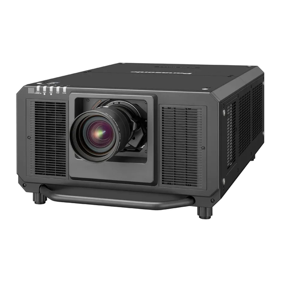
3-chip DLP Based Projector
PT-RZ31K
Model No.
PT-RS30K
© Panasonic Corporation 2016. Unauthorized
copying and distribution is a violation of law.
ORDER NO. VED1610634CE
Rev.-3 (2017-06)
Advertisement
Chapters
Table of Contents

Subscribe to Our Youtube Channel
Related Manuals for Panasonic PT-RS30K


Summary of Contents for Panasonic PT-RS30K
- Page 1 The shape of the supplied power cords varies depending on the country where you purchased the product. For replacement parts and exploded view, refer to the separated manual "PARTS LIST". © Panasonic Corporation 2016. Unauthorized copying and distribution is a violation of law.
- Page 2 PREFACE <RZ31K/RS30K> The service technician is required to read and follow the “Safety Precautions” and “Important Safety Notice” in this service manual. WARNING This service information is designed for experienced repair technicians only and is not designed for use by the general public. It does not contain warnings or cautions to advise non-technical individuals of potential dangers in attempting to service a product.
- Page 3 PREFACE <RZ31K/RS30K> IMPORTANT SAFETY NOTICE There are special components used in this equipment which are important for safety. These parts are marked by 7 in the schematic dia- gram, circuit board diagrams, exploded views and replacement parts list. It is essential that these critical parts should be replaced with manufacturer’s specified parts to prevent shock, fire, or other hazards.
- Page 4 rThe projector may not work properly due to strong radio wave from the broadcast station or the radio. If there is any facility or equipment which outputs strong radio waves near the installation location, install the projector at a location sufficiently far from the source of the radio waves. Or, wrap the LAN cable connected to the PREFACE <RZ31K/RS30K>...
- Page 5 PREFACE <RZ31K/RS30K> CONTENTS 1. Safety Precautions 2. Specifications SECTION 1 SERVICE INFORMATION 1. The name of each part 2. Menu Navigation 3. Service Mode 4. Notes on service 5. Troubleshooting SECTION 2 DISASSEMBLY PROCEDURES 1. Parts Locations 2. Disassembly Instructions SECTION 3 ADJUSTMENTS 1.
- Page 6 PREFACE <RZ31K/RS30K> 1. Safety Precautions 1.1. General Guidelines - For continued safety, no modification of any circuit must be attempted. - Unplug the power cord from the power outlet before disassembling this projector. - Use correctly the supplied power cord and must ground it. - It is advisable to use an isolation transformer in the AC power line before the service.
- Page 7 The specifications of the projector are as follows. 100 V - 120 V / 200 V - 240 V ~ (100 V - 120 V / 200 V - 240 V PT-RZ31K, PT-RS30K alternating current), 50 Hz/60 Hz Power supply...
- Page 8 PREFACE <RZ31K/RS30K> Chapter 7 Appendix — Specifications f When using the projector at an altitude between 2 700 m (8 858') and 4 200 m (13 780') above sea level: 25 °C (77 °F) When the [PROJECTOR SETUP] menu → [OPERATION SETTING] → [OPERATING MODE] is set to [LONG LIFE1], [LONG LIFE2], or [LONG LIFE3], and the operating environment temperature exceeds 35 °C (95 °F), the light output may be reduced to protect the projector.
- Page 9 RGB signal input f Resolution: 640 x 400 to 1 920 x 1 200 f Dot clock frequency: 162 MHz or less f PIAS (Panasonic Intelligent Auto Scanning) system signal input f Resolution: 480i/576i to 1 920 x 1 080 f Dot clock frequency: 148.5 MHz or less...
- Page 10 Chapter 7 Appendix — Dimensions Dimensions PREFACE <RZ31K/RS30K> Unit: mm 2.4. Dimensions 350 (13-25/32") 951 (37-7/16") 290 (11-13/32") 580 (22-27/32") 700 (27-9/16") * Actual dimensions may differ depending on the product. Chapter 7 Appendix — Dimensions r When the optional Long Life Filter Unit (Model No.: ET-EMFU330) is attached 236 - ENGLISH 112.2 (4-13/32") 290 (11-13/32")
-
Page 11: Table Of Contents
SECTION SECTION 1 SERVICE INFORMATION CONTENTS 1. The name of each part ........INF-2 1. -
Page 12: The Name Of Each Part
Chapter 1 Preparation — About your projector SECTION 1 SERVICE INFORMATION <RZ31K/RS30K> About your projector 1. The name of each part 1. 1. Remote controls Remote control Front Bottom A strap can be attached depending on the usage. Remote control indicator 12 Input selection buttons (<RGB1>, <RGB2>, <VIDEO>, Blinks if any button in the remote control is pressed. -
Page 13: Projector Body
SECTION 1 SERVICE INFORMATION <RZ31K/RS30K> Chapter 1 Preparation — About your projector f Avoid contact with liquids or moisture. f Do not attempt to modify or disassemble the remote control. f Do not swing the remote control holding onto the strap when a strap is attached. f Observe the following instructions that are indicated on the caution label at the back of the remote control: g Do not use old battery with new one. -
Page 14: Control Panel
SECTION 1 SERVICE INFORMATION <RZ31K/RS30K> Chapter 1 Preparation — About your projector 11 Remote control signal receiver (rear) 15 Security slot This security slot is compatible with the Kensington security 12 Air exhaust port cables. 13 Control panel 16 <AC IN> terminal 14 Connecting terminals Connect the supplied power cord. - Page 15 SECTION 1 SERVICE INFORMATION <RZ31K/RS30K> Chapter 1 Preparation — About your projector 1. 3. Control panel r Control panel Power on <b> button 11 <MENU> button Sets the projector to projection mode when the <MAIN Displays or hides the main menu. POWER>...
-
Page 16: Connecting Terminals
SECTION 1 SERVICE INFORMATION <RZ31K/RS30K> Chapter 1 Preparation — About your projector 1. 4. Connecting terminals r Connecting terminals <REMOTE 1 IN> terminal/<REMOTE 1 OUT> terminal <DC OUT 1> terminal/<DC OUT 2> terminal These are terminals to connect the remote control for serial This is the USB terminal dedicated for power supply. -
Page 17: Menu Navigation
SECTION 1 SERVICE INFORMATION <RZ31K/RS30K> Chapter 4 Settings — Menu navigation 2. Menu Navigation Menu navigation The on-screen menu (Menu) is used to perform various settings and adjustments of the projector. Navigating through the menu Operating procedure button Press the <MENU> button on the remote control or control panel. f The [MAIN MENU] screen is displayed. - Page 18 SECTION 1 SERVICE INFORMATION Chapter 4 Settings — Menu navigation <RZ31K/RS30K> Press as to select a sub-menu, and press qw or the <ENTER> button to change or adjust settings. f Some items will switch in order as follows each time you press qw. f For some items, press qw to display an individual adjustment screen with a bar scale as shown below.
- Page 19 SECTION 1 SERVICE INFORMATION <RZ31K/RS30K> Chapter 4 Settings — Menu navigation Main menu item [DISPLAY LANGUAGE] [3D SETTINGS] [DISPLAY OPTION] [PROJECTOR SETUP] [P IN P] [TEST PATTERN] [SIGNAL LIST] [SECURITY] [NETWORK] Sub-menu The sub-menu of the selected main menu item is displayed, and you can set and adjust items in the sub-menu. [PICTURE] Sub-menu item Factory default...
- Page 20 SECTION 1 SERVICE INFORMATION <RZ31K/RS30K> Chapter 4 Settings — Menu navigation Sub-menu item Factory default [BLANKING] ― [INPUT RESOLUTION] ― [CLAMP POSITION] [24] [EDGE BLENDING] [OFF] [FRAME RESPONSE] [NORMAL] [FRAME CREATION] ― [FRAME LOCK] ― [RASTER POSITION] ― *1 Depends on the signal input. [DISPLAY LANGUAGE] Details (x page 107) [3D SETTINGS]...
- Page 21 Chapter 4 Settings — Menu navigation SECTION 1 SERVICE INFORMATION <RZ31K/RS30K> [PROJECTOR SETUP] Sub-menu item Factory default [PROJECTOR ID] [ALL] [PROJECTION METHOD] ― [OPERATION SETTING] ― [LIGHT OUTPUT] [83.3%] [BRIGHTNESS CONTROL] ― [STANDBY MODE] [NORMAL] [NO SIGNAL SHUT-OFF] [DISABLE] [NO SIGNAL LIGHTS-OUT] [DISABLE] [INITIAL STARTUP] [LAST MEMORY]...
- Page 22 SECTION 1 SERVICE INFORMATION <RZ31K/RS30K> Chapter 4 Settings — Menu navigation Sub-menu item Factory default [DIGITAL LINK STATUS] ― [NETWORK SETUP] ― [NETWORK CONTROL] ― [NETWORK STATUS] ― [DIGITAL LINK MENU] ― [Art-Net SETUP] [OFF] [Art-Net CHANNEL SETTING] [Art-Net STATUS] ― Note f Some items may not be adjusted or used for certain signal formats to be input to the projector.
-
Page 23: Service Mode
SECTION 1 SERVICE INFORMATION <RZ31K/RS30K> 3. Service Mode This projector has Service Mode in addition to standard on-screen menus (User Mode). This mode enables some menu settings for the service operation. 3. 1. Setting to Service Mode 1. Press the [MENU] button on the control panel of the projector or on the remote controller to display the main menu on the screen. - Page 24 SECTION 1 SERVICE INFORMATION <RZ31K/RS30K> 2. 3DCMS • Setting of the 3D Color Management System operation. - ON : Enable the 3D Color Management system function. (Default setting) - OFF : Disable the 3D Color Management system function. 3. SELF CHECK •...
- Page 25 SECTION 1 SERVICE INFORMATION <RZ31K/RS30K> l How to read the status of light source ㉒– LD1B check (1: normal / 0: abnormal / *: intentional Off) LD1B 1 * 1 1 1 ㉓– LD1S check (1: normal / 0: abnormal / *: intentional Off) LD1S 1 1 1 1 * ㉔–...
- Page 26 SECTION 1 SERVICE INFORMATION <RZ31K/RS30K> l How to read the status of fans ㉖– Fan[1] check (1: normal / 0: abnormal) FAN[1] 1111 1110 1111 1111 1111 ㉗– Fan[2] check (1: normal / 0: abnormal) FAN[2] 1111 1110 1111 1111 1 l Fan/Pump error and projector operation No.
- Page 27 SECTION 1 SERVICE INFORMATION <RZ31K/RS30K> l Cooling pumps location Pump 2 (PUMP-G) Pump 7 (PUMP2S) Pump 1 (PUMP-R) Pump 6 (PUMP2B) Pump 3 (BUMP-B) Pump 4 (PUMP1B) Pump 5 (PUMP1S) 4. POWER OFF MESSAGE • Setting of the shutter function with standby operation - SHUTTER KEEP: When pushing the standby key while the shutter mode is on, the projector keeps the shutter mode on and sets into standby mode.
- Page 28 SECTION 1 SERVICE INFORMATION <RZ31K/RS30K> 11. INDICATOR SETTING • Set this when you want to turn off the indicator LED. – INDICATOR MODE – NORMAL : The indicator maintains lighting (Default) – OFF : The indicator will be forcibly turned off. –...
- Page 29 SECTION 1 SERVICE INFORMATION <RZ31K/RS30K> 3. 3. 2. Additional function of each menu 1. [PICTURE] menu • [AI WINDOW] is added to the setting of the sub menu [DYNAMIC CONTRAST]. Sets up the APL detective area. (AUTO/MANUAL, further settings are available in MANUAL mode) 2.
- Page 30 SECTION 1 SERVICE INFORMATION <RZ31K/RS30K> 4. [PROJECTOR SETUP] menu The following two items are added to the sub-menu. "COOLING CONDITION" Fan control can be set manually. (Usually set to [AUTO].) "HIGH ALTITUDE MODE" Altitude can be set manually. (Usually set to [AUTO].) (2) In the [BRIGHTNESS CONTROL STATUS] sub menu, [DETAILED INFORMATION] is displayed by pressing the [ENTER] key.
- Page 31 SECTION 1 SERVICE INFORMATION <RZ31K/RS30K> (4) The following items are added to the sub menu "STATUS ". 1) Page 2 - VERTICAL TILT Vertical angle - HORIZONTAL TILT Horizontal angle - P.SENSOR Luminance sensor detected value 2) Page 4 - LIGHT DRIVE MODE BRIGHTNESS PRIORITY Light source used time in brightness priority mode 3) Page 7...
- Page 32 SECTION 1 SERVICE INFORMATION <RZ31K/RS30K> 4) Page 8 - DIGITAL LINK VERSION Digital LINK firmware version - FPGA VERSION FPGA firmware version (FPGA1/FPGA2/FPGA3) - CPLD VERSION CPLD firmware version - FM R VERSION Formatter (R) firmware version - FM G VERSION Formatter (G) firmware version - FM B VERSION Formatter (B) firmware version...
- Page 33 SECTION 1 SERVICE INFORMATION <RZ31K/RS30K> 7) Page 11 ~ 12 - AIR FLOW Air flow sensor value/AD value, Sensor correction value/AD value, Clogging threshold/Margin value - FAN Fan rotation mode [TYPE 1 ~ TYPE J] - ALT Altitude mode (ALT1 ~ ALT5) - ATM Air pressure [hPa] - RADIATOR1...
- Page 34 SECTION 1 SERVICE INFORMATION <RZ31K/RS30K> 8) Page 13 ~ 14 - LD1 INFO Information of each bank of LD1 (On count / Runtime / Status*) - LD2 INFO Information of each bank of LD1 (On count / Runtime / Status*) * Status (0 : Off/ 1: On /* : Intentional Off) * Intentional Off •...
- Page 35 SECTION 1 SERVICE INFORMATION <RZ31K/RS30K> 5. [TEST PATTERN] menu • The following test patterns are added. - Focus (background 70% gray) pattern - Checker pattern - Inverted checker pattern INF-25...
- Page 36 SECTION 1 SERVICE INFORMATION <RZ31K/RS30K> 4. Notes on service 4. 1. Before service operation 4. 1. 1. Light source 1. LD(Laser) unit that is mounted on the inside of the light source unit is classified in Class 4 of the safety standards. •...
- Page 37 SECTION 1 SERVICE INFORMATION <RZ31K/RS30K> 4. 1. 4. Lithium battery 1. The lithium battery is used for the internal clock in the A-P.C.Board. So when it consumed it must be replaced. * Use only specified lithium battery. Lithium battery : CR2032 * Used battery must be scrapped according to the instruction.
- Page 38 SECTION 1 SERVICE INFORMATION <RZ31K/RS30K> 4. 2. Service 4. 2. 1. Supporting Methods The basic service policy is shown below. Repair contents Applied parts - [PF] -P.C.Board (Fuse on the primary circuit can be replaced individually) - [PB]-P.C.Board - [D]-P.C.Board Block replacement - [DR]-P.C.Board P.C.Board replacement...
- Page 39 f When switching off the projector, make sure to follow the procedures in “Switching off the projector” (x page 68). Maintenance SECTION 1 SERVICE INFORMATION <RZ31K/RS30K> Outer case 4. 2. 4. Replacement of printed circuit board 1. When the replacement of [A]-P.C.Board (assembly) is needed, back up the memory information such as adjustment data Wipe off dirt and dust with a soft, dry cloth.
- Page 40 SECTION 1 SERVICE INFORMATION <RZ31K/RS30K> Chapter 6 Maintenance — Maintenance/replacement For the air filter unit The section describes the maintenance of the standard air filter unit attached to the projector. This air filter unit is the same as the Replacement Filter Unit (Model No.: ET-EMF330) (accessory/optional accessory).
- Page 41 Chapter 6 Maintenance — Maintenance/replacement SECTION 1 SERVICE INFORMATION <RZ31K/RS30K> Performing maintenance of the air filter unit Fig. 1 Fig. 2 Wash the air filter unit. (Fig. 1) i) Soak the air filter unit in cold or warm water and then lightly rinse it. f Do not use cleaning tools such as brushes.
- Page 42 SECTION 1 SERVICE INFORMATION <RZ31K/RS30K> Chapter 6 Maintenance — Maintenance/replacement f Hook the air filter unit frame at the bottom side to the tabs on the projector body (d), and perform Step 3) in “Removing the air filter unit” in the reverse order to attach. f Confirm that the tabs on the projector body (c) and (d) are hooked to the air filter unit frame.
- Page 43 SECTION 1 SERVICE INFORMATION Chapter 6 Maintenance — Maintenance/replacement <RZ31K/RS30K> Remove the long life filter cover. (Fig. 1) f Remove the long life filter cover fixing screws (two locations at right and left) by turning them counterclockwise, and remove the long life filter cover from the long life filter mount clasp. f When loosening the long life filter cover fixing screws, hold the screws with your hand so they will not fall.
- Page 44 SECTION 1 SERVICE INFORMATION <RZ31K/RS30K> Chapter 6 Maintenance — Maintenance/replacement Attaching the air filter unit Cross section Guide on the long life filter cover (e) Air filter unit Grip on the air filter unit (a) Long life filter cover Air filter unit Grip on the air filter unit (b) Guide on the long life filter cover (f) Fig.
- Page 45 SECTION 1 SERVICE INFORMATION Chapter 6 Maintenance — Maintenance/replacement <RZ31K/RS30K> Resetting the filter counter Turn on the power of the projector. Press the <MENU> button on the remote control or control panel. f The [MAIN MENU] screen is displayed. Press as to select [PROJECTOR SETUP]. Press the <ENTER>...
- Page 46 Light source/temperature/filter indicators SECTION 1 SERVICE INFORMATION <RZ31K/RS30K> When an indicator lights up 5. Troubleshooting If a problem occurs inside the projector, the light source indicators <LIGHT1>/<LIGHT2>, temperature indicator <TEMP>, or filter indicator <FILTER> will inform you by lighting or blinking in red. Check the status of the 5.
- Page 47 SECTION 1 SERVICE INFORMATION <RZ31K/RS30K> Light source indicators <LIGHT1>/<LIGHT2> Indicator status Status Solution f Some of the elements of the light f Turn the <MAIN POWER> switch to <OFF> , and turn on the Lighting in red source are defective and the light power again.
- Page 48 LIFE3], the projector cannot be used at an altitude of 2 700 m (8 858') or higher above sea level. When the Smoke Cut Filter is used, the projector cannot be used at an altitude of 1 400 m (4 593') or higher above sea level. *2 Maintenance of the Smoke Cut Filter is not possible.
- Page 49 SECTION 1 SERVICE INFORMATION <RZ31K/RS30K> 5. 2. Shutdown system This projector provides the shutdown function to set into the standby mode immediately for product safety when the projector has the fan operation error or lightning error. LED indication sta- Self- Shutdown detection Probable cause OSD warning, others...
- Page 50 SECTION 1 SERVICE INFORMATION <RZ31K/RS30K> LED indication sta- Self- OSD warning, oth- Shutdown detection Probable cause diagnosis Optical module temperature sensor a Lower than 8ºC for more than Operating temperature is too low. – 5min. after lighting on. Intake air temperature sensor (U14) a Lower than 0ºC Out of operating temperature for DMD and LD...
- Page 51 SECTION 1 SERVICE INFORMATION <RZ31K/RS30K> LED indication sta- Self- OSD warning, oth- Shutdown detection Probable cause diagnosis Intake temperature sensor for filter clogged "CLEAN THE AIR FIL- FILTER LED lights Filter clogged a Depending on the installed TER" warning only environment "THE AIR FILTER HAS Filter detection switch...
- Page 52 SECTION 1 SERVICE INFORMATION <RZ31K/RS30K> 5. 3. System log data acquisition method * The log data acquisition via LAN terminal or serial terminal. 5. 3. 1. Equipment to be used 1. Computer : Use it for the transfer of backup data. 2.
- Page 53 • Select [Serial] and setup the port, baud rate and parity. LAN terminal connection • The factory default setting of the user name is "admin1" and the password is "panasonic". [Note] If the Username and Password has been changed, please select serial terminal connection.
- Page 54 SECTION 1 SERVICE INFORMATION <RZ31K/RS30K> 5. Select "Log (SYSTEM)" and set the log display method, then click the [Get] button. * Select "Show All Log" or "Show Error Only" 6. Log is displayed. INF-44...
- Page 55 SECTION 1 SERVICE INFORMATION <RZ31K/RS30K> 5. 3. 4. Error cord of system log Self-test indica- Error code (hex) Details Probable cause tion External temperature is too high. Intake air temperature warning 00000000 00000001 Intake ventilation holes are blocked. Mounting of heatsink is abnormal. Optical module temperature warning 00000000 00000002 Ventilation holes are blocked.
- Page 56 SECTION 1 SERVICE INFORMATION <RZ31K/RS30K> Self-test indica- Error code (hex) Details Probable cause tion Air filter clogged Air filter clogged warning 00000000 00000002 Filter usage time exceeds a setting time No air filter detected 00000000 00000004 Air filter is not mounted Not used 00000000 00000008 –...
- Page 57 SECTION 1 SERVICE INFORMATION <RZ31K/RS30K> Self-test indica- Error code (hex) Details Probable cause tion Not used 00000000 00000008 – Not used 00000000 00000010 - Not used 00000000 00000020 - FAN 1 (RADIATOR1) error 00000000 00000040 FAN 2 (RADIATOR2) error 00000000 00000080 FAN 3 (RADIATOR3) error 00000000 00000100 FAN 4 (RADIATOR4) error...
- Page 58 SECTION 1 SERVICE INFORMATION <RZ31K/RS30K> Self-test indica- Error code (hex) Details Probable cause tion Power CPU communication error 00000000 00000080 Communication error on Power CPU GEOMETRY communication error 00000000 00000100 Communication error on Geometry IC FRC error 00000000 00000200 Program transferring error to FRC FM-R TEST Fail 00000000 00000400 Abnormal on FM startup mode...
- Page 59 SECTION 1 SERVICE INFORMATION <RZ31K/RS30K> 5. 4. Troubleshooting * The letters in the left of inspection items indicate the P.C. Boards related to their respective descriptions. ■ Power does not turn ON. ([STANDBY/ON] LED does not light in red) Check the connection of each connector Connect the cables firmly PB3~G3, PB4~DG3/A1, R1~G9 Check the voltage [3.3V] at pin-1 of connector [G3].
- Page 60 SECTION 1 SERVICE INFORMATION <RZ31K/RS30K> ■ Light source does not turn on. (Both of [LIGHT1,LIGHT2] LED blink 3 times) Check the connection of each connector. PF6/PF7/PF8/PF9~D1, G4/G5/G6/G7~D3, D2~DR2/DR5, Connect the cables firmly. D5~DR7/DR8, DR1/DR3/DR4/DR6~LD Check the driver input voltage. Check the voltage [DC12V] at pin 13 of connector [D3] at the Replace [G] P.C.Board lighting mode.
- Page 61 SECTION 1 SERVICE INFORMATION <RZ31K/RS30K> ■ No picture or abnormal picture is output Is a menu screen displayed ? Check connection of each connector. Connect the cables firmly. Check the input image other than solid black image. No image with VIDEO input. Follow the section "VIDEO input check"...
- Page 62 SECTION 1 SERVICE INFORMATION <RZ31K/RS30K> ■ VIDEO input check One of the input (Y/C, RGB2, HDMI) can be displayed. Follow the section "A-P.C.Board operation check" Check the waveform at C3013. Check IC3501, X3501 and peripheral circuit. Check IC3062 and peripheral circuit. Check the waveform at C3005.
- Page 63 SECTION 1 SERVICE INFORMATION <RZ31K/RS30K> ■ RGB1 input check One of the input (RGB2, HDMI) can be displayed. Check the input waveform at IC3010. Check IC3010 and peripheral circuit. C3059(R), C3058(G), C3060(B), TPA09(HS), TPA10(VS) Check L3044, L3043, L3042, Q3036, Q3037, Q3038 and periph- eral cuircuit.
- Page 64 SECTION 1 SERVICE INFORMATION <RZ31K/RS30K> ■ DVI-D input check Check the image of RGB2 input with PinP mode. Select PinP mode and input RGB1 for main and input RGB2 for sub. Check the waveform at R3259 (AE_ACT). Check R3493(ACT), IC3058 and peripheral circuit. Check the waveform at R3289(G9), R3260(CLK), R3259(HS, VS).
- Page 65 SECTION 1 SERVICE INFORMATION <RZ31K/RS30K> ■ DIGITAL LINK input check HDMI signal can be displayed. Check IC3010 and peripheral circuit. Is [DIGITAL LINK MODE] of the setup menu [AUTO] or [DIGITAL Set [AUTO] or [DIGITAL LINK]. with user menu LINK]? Check if the voltage [3.3V] is on L2005, [1.8V] on L2008 DIGITAL LINK software version is displayed on the SELF and [1.0V] on L2011, check X2001, C2004, IC2002,...
- Page 66 SECTION 1 SERVICE INFORMATION <RZ31K/RS30K> ■ SDI2 input check Check power supply lines. Check IC3059, IC3351 and peripheral circuit. IC3059-1 pin : 3.3V, IC3351-5pin : 1.2V Check the voltage is less than [0.4V] at pin 7 of IC3072. Check IC3072 and peripheral circuit. Check clock frequency at R3444.
- Page 67 SECTION 1 SERVICE INFORMATION <RZ31K/RS30K> ■ Main microprocessor operation check Check the clock waveform at R3622. Check X3501 and peripheral circuit. 35.455MHz Check the voltage [3.3V] at pin1 of A1 connector and [5V] at pin Replace cable [P6] - [A1], and [PF]/[PB]-P.C.Board. Check that the voltage is 1.2V at R3826.
- Page 68 SECTION 1 SERVICE INFORMATION <RZ31K/RS30K> ■ DG/FM-P.C.Board operation check Check the connectors and cables. A side: DG2 (B to B connector), DG3, DG4, DG21–DG26 Connect the connector firmly. B side: DG1 (B to B connector) * Replace cable if the pin of the connector bend. * Check that the pin of the connector does not bend.
- Page 69 SECTION 1 SERVICE INFORMATION <RZ31K/RS30K> Check DDP*_RSTOUT line. IC7001/IC7301/IC7601 T24pin = 3.3V Is LD lighting? Check LD, LD driver. Check IC3501 (Main microprocessor and periph- eral circuit. Check the clock waveform <1> DG Check X5004, IC5019 and peripheral circuit. Both pins at R5259 Clock: 132MHz Check sync signal output from IC5001(FPGA2).
- Page 70 SECTION 1 SERVICE INFORMATION <RZ31K/RS30K> ■ Remote control does not respond ● No respond only from front side. Check the cable connection between connectors [G9] and The signal waveform can be detected at pin 5 of connector [G9] [R1]. when pressing the button on the remote control. Replace [R]-P.C.Boad.
- Page 71 SECTION 1 SERVICE INFORMATION <RZ31K/RS30K> ■ SERIAL IN/OUT does not respond Check the cable connection of JK6103/JK6104 (SERIAL IN/ Connect the connector firmly OUT). The signal waveform can be detected at pins 10, 12, 16, 17 of Check IC6105 and peripheral circuit. IC6123 when sending the serial commands.
- Page 72 SECTION 1 SERVICE INFORMATION <RZ31K/RS30K> INF-62...
- Page 73 SECTION SECTION 2 DISASSEMBLY PROCEDURES Illustrations of the projector and other parts may vary from the actual product. CONTENTS 1. Parts Locations ......... . . DIS-2 1.
-
Page 74: Parts Locations
SECTION 2 DISASSEMBLY PROCEDURES <RZ31K/RS30K> 1. Parts Locations 1. 1. Electrical parts location (P.C.Boards) D(LD-2) D(LD-1) DR(LD-B) BF M1 D(LD-4) D(LD-3) DR(LD-F) RE RD Board Board Board Function summary Function summary Function summary Name Name Name Air filter sensor switch Relay Board (Pump fans) Control terminal / Fan,Iris,Motor Drive Temp sensor... -
Page 75: Electrical Parts Location (Fans)
SECTION 2 DISASSEMBLY PROCEDURES <RZ31K/RS30K> 1. 2. Electrical parts location (Fans) Color prism 4 fan Color prism 1 fan Exhaust 4 fan PW 1 fan PW 2 fan Exhaust 3 fan LD driver 2 fan Exhaust 2 fan LD driver 1 fan Exhaust 1 fan Color prism 3 fan Color prism 2 fan... -
Page 76: Electrical Parts Location (Sensors)
SECTION 2 DISASSEMBLY PROCEDURES <RZ31K/RS30K> 1. 4. Electrical parts location (Sensors) Thermistor (LD2B) Thermistor (LD2S) Temp. sensor (Exhaust)(M1-PCB) Thermistor (LD1S) Thermistor (LD1B) Thermistor (DMD) Motion sensor IC (A-PCB) Temp. sensor (Circuit)(M1-PCB) Pressure sensor IC (RM-PCB) Color sensor (M3-PCB) Airflow sensor (M2-PCB) Temp. -
Page 77: Optical Parts Location
SECTION 2 DISASSEMBLY PROCEDURES <RZ31K/RS30K> 1. 6. Optical parts location DMD top cover Liquid cooling unit 2 DMD Liquid LD block 2S LD block 2B cooling unit (LD2S-1-6) (LD2B-1-6) DMD block Lighting case 2 DMD bottom cover LC joint block Mechanical shutter Lighting mirror block Rod assy... -
Page 78: Disassembly Instructions
SECTION 2 DISASSEMBLY PROCEDURES <RZ31K/RS30K> 2. Disassembly Instructions [ Caution ] • Before disassembly of the projector, turn off the power switch and disconnect the power plug from the wall outlet. [Note] • During the disassemble work, please wear gloves to protect your hands from metal parts and shield plate. •... - Page 79 SECTION 2 DISASSEMBLY PROCEDURES <RZ31K/RS30K> 2. 1. 2. Removal and insert procedure Removal procedure of fine coaxial cable connector • Hold both ends of cable connector, and pull out a vertical direction to the circuit board. • Do not pull on cable. [ Notes when removing the signal block ] •...
- Page 80 SECTION 2 DISASSEMBLY PROCEDURES <RZ31K/RS30K> * Before Disassembly the projector, turn off the POWER switch and disconnect the power plug from the wall outlet. * To assemble, reverse the disassembly procedures. Completed Product 2. 2. Projection lens removal 2. 3. Top cover (F)/(R) removal 2.
-
Page 81: Projection Lens Removal
SECTION 2 DISASSEMBLY PROCEDURES <RZ31K/RS30K> 2. 2. Projection lens removal 1. Remove a lens fixing screw. 2. Remove the projection lens by turning it counterclockwise while pressing the lens release button. (* In advance move the projection lens to the home position.) Lens fixing screw Lens release button 2. -
Page 82: Front Cover And Rear Cover Removal
SECTION 2 DISASSEMBLY PROCEDURES <RZ31K/RS30K> 2. 4. Front cover and Rear cover removal 1. Unscrew 2 screws-A, 4 screws-B and remove the front cover. 2. Unscrew 4 screws-C, 2 screws-D and remove the rear cover. Rear cover [BR]-P.C.Board Front cover [R]-P.C.Board DIS-10... -
Page 83: Side Cover (L)/(R) Removal
SECTION 2 DISASSEMBLY PROCEDURES <RZ31K/RS30K> 2. 5. Side cover (L)/(R) removal 1. Loosen a screw-A and remove the filter cover. 2. Unhook the air filter's hook and remove the air filter. 3. Unscrew 8 screws-B and remove the side cover (R). 4. -
Page 84: Signal Block Removal
SECTION 2 DISASSEMBLY PROCEDURES <RZ31K/RS30K> 2. 6. Signal block removal 1. Unscrew 4 screws-A and remove the signal block upward. Signal block Terminal fixing screws Terminal frame 2. Unscrew each 5 screws-A on the boards and remove the [DG]-P.C.Board, [G]-P.C.Board and [A]-P.C.Board. [G]-P.C.Board [DG]-P.C.Board [A]-P.C.Board... -
Page 85: Power Pb Block Removal
SECTION 2 DISASSEMBLY PROCEDURES <RZ31K/RS30K> 2. 7. Power PB block removal 1. Unscrew 6 screws-A, 2 screws-B and remove the power PB block. 2. Unscrew 4 screws-C, 2 screws-D and remove the circuit intake fan block. 3. Unscrew 2 screws-E and remove the LD driver 1 fan block. Circuit intake fan block Power PB block LD driver 1 fan block... -
Page 86: Frames Removal
SECTION 2 DISASSEMBLY PROCEDURES <RZ31K/RS30K> 2. 8. Frames removal 1. Unscrew 4 screws-A, 4 screws-B and remove the frame (B). 2. Unscrew 4 screws-C and remove the frame (C). 3. Unscrew 4 screws-D and remove the frame (F). 4. Unscrew each 4 screws-E on the LD support metal. Unscrew 4 screws-F and remove the frame (L). Frame (F) Frame (C) Frame (L) -
Page 87: Exhaust Fan Block Removal
SECTION 2 DISASSEMBLY PROCEDURES <RZ31K/RS30K> 2. 9. Exhaust fan block removal 1. Remove the frame (B) following to the step [2.8. Frames removal]. 2. Unscrew each 3 screws-A, 2 screws-B and remove the hexaust fan block and [BF]-P.C.B. [BF]-P.C.Board Exhaust fan block (L) Exhaust fan block (R) Exhaust fan block (R) Exhaust 4 fan... -
Page 88: Ld Driver Block Removal
SECTION 2 DISASSEMBLY PROCEDURES <RZ31K/RS30K> 2. 10. LD driver block removal 1. Unscrew each 5 screws-A and remove the LD driver block (F) and (R). LD driver block (F) LD driver block (R) LD driver block (F) LD driver block (R) LD driver 2 fan [DR]-P.C.Board [RR]-P.C.Board... -
Page 89: Power Pf Block Removal
SECTION 2 DISASSEMBLY PROCEDURES <RZ31K/RS30K> 2. 11. Power PF block removal 1. Unscrew 8 screws-A, 1 screw-B and remove the power PF block. [PF]-P.C.Board AC inlet & SW unit PF isolation sheet Power PF block 2. 12. Frame (R) removal 1. -
Page 90: Pw Fan, Radiator Fan Block Removal
SECTION 2 DISASSEMBLY PROCEDURES <RZ31K/RS30K> 2. 13. PW fan, radiator fan block removal 1. Unscrew 2 screws-A, 2 screws-B and remove the partition sheet and PW fan block. 2. Unscrew each 3 screws-C and remove the radiator fan blocks (F) and (R) [RF]-P.C.Board Radiator 10 fan Radiator 12... -
Page 91: Rod Ass'y Removal
SECTION 2 DISASSEMBLY PROCEDURES <RZ31K/RS30K> 2. 14. Rod ass'y removal 1. Remove the radiator fan block (F) following to step [2.13. PW fan, radiator fan block removal]. 2. Unscrew 2 screws-A and 1 screw-B on the liquid cooling tank and remove the radiator 2B/liquid cooling tank 2B upward. -
Page 92: Lighting Block 2 Removal
SECTION 2 DISASSEMBLY PROCEDURES <RZ31K/RS30K> 2. 15. Lighting block 2 removal 1. Unscrew 5 screws-A, 1 screw-B, 2 screws-C and remove the lighting block 2 upward. [RT]-P.C.Board Torque: 70±10 N•cm [RP]-P.C.Board Lighting block 2 2. 16. Liquid cooling unit 2 removal 1. -
Page 93: Ld Unit 2 Removal
SECTION 2 DISASSEMBLY PROCEDURES <RZ31K/RS30K> 2. 17. LD unit 2 removal 1. Remove the lighting block 2 following to the step [2.15. Lighting block 2 removal]. 2. Unscrew 2 screws-A and remove the liquid cooling tank 2S. 3. Unscrew 1 torx screw-B and 5 screws-C, and remove the LD2S block (LD2S-1~6). 4. -
Page 94: Phosphor Wheel 2 Removal
SECTION 2 DISASSEMBLY PROCEDURES <RZ31K/RS30K> 2. 18. Phosphor wheel 2 removal 1. Unscrew 1 torx screw-A, 5 screws-B and remove the PW cover. 2. Unscrew 2 screws-C and remove the PW support metal upward. 3. Unscrew 2 screws-D and remove the phosphor wheel 2 upward. [Note] •... -
Page 95: Lighting Block 1 Removal
SECTION 2 DISASSEMBLY PROCEDURES <RZ31K/RS30K> 2. 19. Lighting block 1 removal 1. Remove the Lighting block 2 following to step [2.15. Lighting block 2 removal]. 2. Unscrew 5 screws-A and remove the LC joint unit upward. 3. Unscrew 5 screws-B, 2 screws-C and remove the lighting block 1 upward. Torque: 70±10 N•cm LC joint unit Lighting block 1... -
Page 96: Ld Unit 1 Removal
SECTION 2 DISASSEMBLY PROCEDURES <RZ31K/RS30K> 2. 21. LD unit 1 removal 1. Remove the lighting block 1 following to the step [2.19. Lighting block 1 removal]. 2. Unscrew 2 screws-A and remove the liquid cooling tank 1S. 3. Unscrew 1 torx screw-B, 5 screws-C and remove the LD1S block (LD1S-1~6). 4. -
Page 97: Phosphor Wheel 1 Removal
SECTION 2 DISASSEMBLY PROCEDURES <RZ31K/RS30K> 2. 22. Phosphor wheel 1 removal 1. Unscrew 1 torx screw-A, 5 screws-B and remove the PW cover. 2. Unscrew 2 screws-C and remove the PW support metal upward. 3. Unscrew 2 screws-D and remove the phosphor wheel 2 upward. [Note] •... -
Page 98: Dmd Block/Liquid Cooling Unit Removal
SECTION 2 DISASSEMBLY PROCEDURES <RZ31K/RS30K> 2. 23. DMD block/liquid cooling unit removal 1. Loosen 6 screws-A and remove the DMD top cover. 2. Loosen 4 screws-B and remove the prism fan block. 3. Unscrew 1 screw-C, 4 screws-D and remove the color prism 2 fan and 3 fan. DMD cover block Color prism 1 Color prism... - Page 99 SECTION 2 DISASSEMBLY PROCEDURES <RZ31K/RS30K> 6. Unscrew 1 screw-K, 4 screws-L and remove the liquid cooling tank support metal. 7. Unscrew 8 screws-M and remove the DMD radiator from the intake duct block. 8. Remove the DMD block/liquid cooling unit. Intake fan block Ball point driver [RD]-P.C.Board...
-
Page 100: Engine Exhaust Fans, Dmd Cover Bottom Removal
SECTION 2 DISASSEMBLY PROCEDURES <RZ31K/RS30K> 2. 24. Engine exhaust fans, DMD cover bottom removal 1. Loosen 2 screws-A, unscrew 1 screw-B and remove the engine exhaust fan block. Engine 2. Loosen 2 screws-C, unscrew 2 screws-D and remove the DMD cover bot- exhaust 2 fan tom. -
Page 101: Mirror Block Removal
SECTION 2 DISASSEMBLY PROCEDURES <RZ31K/RS30K> [How to remove the WOB frame & Shutter block] [Note] • Move the Lens shift unit to the front end. • When you move the Lens shift unit manually, you should Insert the flat driver into the groove of focus motor on the take the lens calibration. -
Page 102: Lens Mount Block Removal
SECTION 2 DISASSEMBLY PROCEDURES <RZ31K/RS30K> 2. 27. Lens mount block removal 1. Remove the lighting block 2 following to step [2.15. Lighting block 2 removal]. 2. Remove the DMD block following to step [2.23. DMD block removal]. 3. Remove the mirror block following to step [2.26. Mirror block removal]. 4. -
Page 103: Reference> Wiring Connection
SECTION 2 DISASSEMBLY PROCEDURES <RZ31K/RS30K> <Reference> Wiring connection Top view DIS-31... - Page 104 SECTION 2 DISASSEMBLY PROCEDURES <RZ31K/RS30K> Signal block top view Signal block side view DIS-32...
- Page 105 SECTION 2 DISASSEMBLY PROCEDURES <RZ31K/RS30K> RT-PCB and surrounding part top view RR, RP-PCB and surrounding part top view DIS-33...
- Page 106 SECTION 2 DISASSEMBLY PROCEDURES <RZ31K/RS30K> DIS-34...
- Page 107 SECTION SECTION 3 ADJUSTMENTS Illustrations of the projector and other parts may vary from the actual product. CONTENTS 1. Adjustment item and procedure ......ADJ-2 1.
-
Page 108: Adjustment Item And Procedure
SECTION 3 ADJUSTMENTS <RZ31K/RS30K> 1. Adjustment item and procedure When the following parts are disassembled or replaced, please adjust the items according to the table below. Adjustment Item Replaced Component Remarks 1.1. Lighting area adjustment Parts in the DMD block, Lighting block 1.2. -
Page 109: Lighting Area Adjustment
SECTION 3 ADJUSTMENTS <RZ31K/RS30K> 1. 1. Lighting area adjustment 1. 1. 1. Lighting area confirmation 1. Check if any shade is visible in the DMD effective display area. Lighting area • Make the projection environment as dark as possible, and project an all-white and all-black pattern of internal pattern. -
Page 110: Convergence Adjustment
SECTION 3 ADJUSTMENTS <RZ31K/RS30K> 1. 2. Convergence adjustment 1. 2. 1. Electrical convergence adjustment EXTRA OPTOPN • This function is to align each R/G/B convergence in pixels electrically. DYNAMIC GAMMA MODE [Note] Because of using the entire pixels of DMD, the edge pixel of the pro- 3DCMS SELF CHECK jected screen is missing when adjusted. - Page 111 SECTION 3 ADJUSTMENTS <RZ31K/RS30K> 2) Adjust the horizontal position by turning the H adjustment screw. H-Adj. Screw(R) GREEN GREEN GREEN Adjust horizontal Adjust horizontal Adjust horizontal H-Adj. Screw(G) NEXT ENTER ENTER NEXT ENTER NEXT Adjust horizontal Adjust horizontal Adjust horizontal NEXT ENTER ENTER...
- Page 112 SECTION 3 ADJUSTMENTS <RZ31K/RS30K> 1. 2. 3. Usage of special wrench • It is very hard to access the fixing screws on the G-DMD unit in the state of DMD block mounting on the set. We provide a special wrench for convergence adjustment. Special wrench part no.: DPKW1001ZA G-DMD fixing screws ADJ-6...
-
Page 113: Eeprom Data Transfer
SECTION 3 ADJUSTMENTS <RZ31K/RS30K> 1. 3. EEPROM data transfer 1. 3. 1. Equipment to be used 1. Computer : Use it for the transfer of backup data. 2. Communication cable : Serial terminal connection D-sub 9pin (male/female RS-232C straight) LAN terminal connection LAN cable (When connecting directly, use a cross cable) 3. - Page 114 None IP Address 192.168.0.8 Username admin1 Password panasonic Command Port 1024 Serial terminal connection • Select [SERIAL] menu and set up the Serial Port, Baudrate and Parity of the PC LAN terminal connection • Select [LAN] menu and set up the IP address, Username, Password and Command Port of the projector.
- Page 115 SECTION 3 ADJUSTMENTS <RZ31K/RS30K> 5. Select the "Backup (EEPROM)” tab and put a checkmark to the "REPLACE A-PWB" of "COPY MODE" item. Then click the [READ EEPROM] button. 6. Select the save place and click [Save(S)] button. 7. Once the progress bar reaches the right side end, it is a read completion of the data. •...
- Page 116 SECTION 3 ADJUSTMENTS <RZ31K/RS30K> 1. 3. 4. Restore the backup EEPROM data (After circuit board replace) 1. Switch the projector to "Normal-Standby" mode (STANDBY/ON indicator is lighting in red). 2. Start up service software [DataLogBackup.exe] with a computer. 3. Select [Setting] of [Option] menu, then select connection method and enter the setting information of the projector. 4.
-
Page 117: Lens Calibration
SECTION 3 ADJUSTMENTS <RZ31K/RS30K> 1. 4. Lens calibration 1. Select sub menu [LENS CALIBRATION] of [PROJECTOR SETUP] menu. 2. Select the used lens type. • NORMAL : When using the other than ET-D75LE95 • D75LE95 : When using the ET-D75LE95 (ultra short throw lens) PROJECTROR SETUP DATE AND TIME SCHEDULE... -
Page 118: Clog Sensor Calibration
SECTION 3 ADJUSTMENTS <RZ31K/RS30K> 1. 6. Clog sensor calibration [Note]] EXTRA OPTOPN • Projector should be completely assembled and the adjustable feet are com- DYNAMIC GAMMA MODE pletely accommodated in the body. 3DCMS SELF CHECK • Place the projector on the floor and replace the air filter with a new one. SHUTTER KEEP POWER OFF MESSAGE •... -
Page 119: Ld Unit Runtime Reset
SECTION 3 ADJUSTMENTS <RZ31K/RS30K> 1. 8. LD unit runtime reset When replacing the LD unit, the LD unit runtime should be reset by using the service tool. 1.8.1. Equipment to be used 1. Computer : Use it for runtime reset with service tool. 2. - Page 120 None IP Address 192.168.0.8 Username admin1 Password panasonic Command Port 1024 Serial terminal connection • Select [SERIAL] menu and set up the Serial Port, Baudrate and Parity of the PC. LAN terminal connection • Select [LAN] menu and set up the IP address, Username, Password and Command Port of the projector.
- Page 121 SECTION 3 ADJUSTMENTS <RZ31K/RS30K> [Display example] The open failure occurs on the LD1(B)-3. When the open failure occurred, the text characters becomes red. In addition, "NG" is displayed on status. [Reference] All LD units location LD2S-6 LD2S-3 LD2B-1 LD2B-4 LD2S-5 LD2S-2 LD2B-2 LD2B-5...
- Page 122 SECTION 3 ADJUSTMENTS <RZ31K/RS30K> 7. A confirmation window is displayed. If LD No. is correct, click the [OK] button and reset the runtime. Display example of LD1(B)-3 reset 8. Completion screen is displayed, and click the [OK] button. Confirm the runtime is set to 0h. Display example of LD1(B)-3 reset 9.
-
Page 123: Ld Unit Status Reset
SECTION 3 ADJUSTMENTS <RZ31K/RS30K> 1. 9. LD unit status reset f The error information is stored in the memory if the projector turn on in the state of disconnecting of LD unit connectors. In this case, to clear the error status by using the LDResetTool. (Runtime is not reset.) 1. -
Page 124: Firmware Update Procedure
SECTION 3 ADJUSTMENTS <RZ31K/RS30K> 2. Firmware update procedure * Firmware updating can be done via the LAN terminal or the serial terminal. (Updating of DIGITAL LINK software can be done via the serial terminal only.) 2.1. Equipment to be used 1. - Page 125 None IP Address 192.168.0.8 Username admin1 Password panasonic Command Port 1024 Serial terminal connection • Select [SERIAL] menu and set up the Serial Port, Baudrate and Parity of the PC. LAN terminal connection • Select [LAN] menu and set up the IP address, Username, Password and Command Port of the projector.
- Page 126 SECTION 3 ADJUSTMENTS <RZ31K/RS30K> 5. Click [load] button which you want to update the software. 6. Select the new software, and click [Open] button. 7. After loading the software, a checkmark and path name to the software and a version will be displayed on the window. Click [Update] button to start updating of the software.
- Page 127 SECTION 3 ADJUSTMENTS <RZ31K/RS30K> 8. If the version of the software is correct click the [OK] button and start updating. [Note] • During updating, the LED indicators on the projector will light as the below ON/STANDBY LIGHT1 LIGHT2 TEMP Main Lit in red Blink in red each others Lid in green (all)
- Page 128 SECTION 3 ADJUSTMENTS <RZ31K/RS30K> ADJ-22...
- Page 129 SECTION Important Safety Notice Components identified by the international symbol 7 have special characteristics important for safety. When replacing any of these components, use only the manufacturer's specified ones. ■ Notes 1. HOT and COLD indications The power circuit board contains a circuit area using a separate power supply to isolate the ground connection. The circuit is defined by HOT and COLD indications in the schematic diagram.
-
Page 130: Block Diagram
SECTION 4 SCHEMATIC DIAGRAMS 1. Block Diagram 1.1. Power Supply Block Diagram (PF-PCB/PB-PCB) R9003 T9200 D9012 F9002 1,2,3 G-PCB(G2) IC9223 SWITCHING F9007 380V_A DC-DC TRANSFORMER RL9000 RL9002 LD DRIVER (LD1S) RECTIFIER P16V_A ON/OFF DG-PCG (DG3) T9201 IC9209 IC9213 SWITCHING DC-DC 380V_B 25,26 LD DRIVER (LD2S) - Page 131 SECTION 4 SCHEMATIC DIAGRAMS 1.2. LD Driver Block Diagram (D-PCB/DR-PCB LD1B/LD2B) DR-P.C.Board D-P.C.Board [LD1B] T9601 RDAT_DR LD1B TEMP WDAT_DR FET DRIVER Q9701 F9601 380V CLK_DR Q9602 CS_DR YE_PWM Q8053 Q8052 Q8047 Q8065, Q8054 B_PWM LD1B-4 IC9601 Q8066 Q9603 POWER CONTROL 3.3V LD1B-5 Q8064...
-
Page 132: Ld Driver Block Diagram (D-Pcb/Dr-Pcb Ld1S/Ld2S)
SECTION 4 SCHEMATIC DIAGRAMS 1.3. LD Driver Block Diagram (D-PCB/DR-PCB LD1S/LD2S) DR-P.C.Board D-P.C.Board [LD1S] T9601 RDAT_DR LD1S TEMP WDAT_DR FET DRIVER Q9701 F9601 380V CLK_DR Q9602 CS_DR YE_PWM Q8054 Q8053 Q8052 Q8047 Q8065, B_PWM LD1S-4 IC9601 Q8066 Q9603 POWER CONTROL 3.3V LD1S-5 Q8064... -
Page 133: System Control Block Diagram (G-Pcb)
SECTION 4 SCHEMATIC DIAGRAMS 1.4. System Control Block Diagram (G-PCB) (POWER:IC6541[G]) (POWER:IC6545 [G} ) C-PRISM4 FAN C-PRISM1 FAN M2-PCB RE-PCB SENS PWM SENS AIRFLOW TL-PCB SENSOR LED. Engine Intake FAN2 Engine Intake FAN1 M1-PCB (POWER:IC6553[G]) (POWER:IC6554[G]) SENS SENS SN1401 M1-PCB SCL/SDA PHOTO IC SL-PCB... -
Page 134: Signal Block Diagram (A-Pcb)
SECTION 4 SCHEMATIC DIAGRAMS 1.5. Signal Block Diagram (A-PCB) A-P.C.Board IC3072 SDI_EQ_SCK/SDI_EQ_SDO +3.3V STB JK3008 CABLE EQUALIZER SDI_EQ_SDI +5V STB SDI-IN1 To PB-P.C.Board +3.3V_A SDI_EQ_SS (PB3) +3.3V_B +12V SDI_EQ_CDN/3GEQ_SDO_P/3GEQ_SDO_N IC3071 SDI_EQ_SCK/SDI_EQ_SDO JK3009 CABLE EQUALIZER SDI_EQ_SDI SDI-IN2 IC3501 SDI_EQ_SS2 CPU & IP/RESIZE X3501 SDI_EQ_CDN2/3GEQ_SDO_P2/3GEQ_SDO_N2 Clock Gen. -
Page 135: Signal Block Diagram (Dg-Pcb/Fm-Pcb)
SECTION 4 SCHEMATIC DIAGRAMS 1.6. Signal Block Diagram (DG-PCB/FM-PCB) FM-P.C.B (G) DG-P.C.B DG21 IC4003 DMD RZ12K : WUXGA 1920 x 1200 IC5001 RS11K : SXGA+ 1400 x 1050 IC7001 X5004 FPGA2 H/V/ACT/CL DG22 Odd Even GREEN BIAS RESET FORMATTER LVDS 31 pair IC4001 IC4002 (GREEN) -
Page 136: Interconnection Block Diagram
SECTION 4 SCHEMATIC DIAGRAMS 2. Interconnection Block Diagram H-SHIFT MOTOR FILTER TEMP LIGHT2 LIGHT1 POWER INTAKE AIR TEMP V-SHIFT MOTOR 2.1. Inter connection Diagram M1-PCB (4P) (12P) (3P) R-PCB AC INLET FOCUS MOTOR (4P) (4P) (4P) FILTER DETECTION RM-PCB F-PCB (14P) (10P) (2P) - Page 137 SECTION 4 SCHEMATIC DIAGRAMS 2.2. Power supply flow and timing chart PB-P.C.B A-P.C.B PF-PCB +3.3VSTB +3.3VECO 380V_A 380V_A_AC POWER SUPPLY 380V_B UART_TXD/RXD_A +3.3VSTB CIRCUIT UART_TXD/RXD_A RELAY_ON DC-DC IC3501 RELAY_ON P16V_A_STB STB_ON +3.3VSTB Supply to Main CPU <MAIN CPU> P16V_A_STB AC_OFF_DET_A LOWB_ON POWER REG.
- Page 138 SECTION 4 SCHEMATIC DIAGRAMS 3. Schematic Diagram +12VB L3007 J0JHC0000078 G1C100K00031 3.1. A-PCB (1/3) +5V_A2 L3045 +5V_A R3221 C3232 0.1u R3003 Q3033 B1ABBB000102 *R3346 R3024 113 C3140 R3292 C3265 GUARD_R J0JHC0000078 IC3058 R3004 36 R3025 113 R3223 R3347 GUARD_R Q3014 B1ABDF000018 +12V_A1BUFF L3006...
- Page 139 SECTION 4 SCHEMATIC DIAGRAMS A-PCB (2/3) +3.3V_FPGA +3.3VSTB +1.2V_SCX2 +3.3V_BVCC +3.3V_A1_REG +5VSTB +3.3VSTB +3.3VSTB +1.2V_SCX2 +1.5V_DDR3 C3586 C3587 IC3586 R3509 R3599 0.1u C0DBFYY00190 L3871 J0JJC0000022 C3588 +1.2V_X2_PLL R3596 +3.3V_BVCC C3701 0.1u R3507 C3871 C3589 R3593 L3542 J0JJC0000022 0.1u C3563 R3508 C3511 C3564 3.3V_BVCC_ADC...
- Page 140 SECTION 4 SCHEMATIC DIAGRAMS A-PCB (3/3) 3.2. DG-PCB (1/3) +1.8VSTB_NT0 +3.3VSTB_NT1 to ADV +1.8VSTB_NT2 CONFIGURATION *R2060 AH_TMDS_CLK_P *C5574 0.1u C2010 HDMISER_TMDSDATAP_2 *IC2001 *R2061 ERJ2GE0R00X AH_TMDS_CLK_N AH_TMDS_CLK_P AH_TMDS_CLK_P *C5575 0.1u 1000p R2085 1k HDMISER_TMDSDATAN_2 *IC2001 ERJ2GE0R00X AH_TMDS_CLK_N AH_TMDS_CLK_N TEST POINT I/O BANK 13/14 I/O BANK 12 I/O BANK 16 I/O BANK 15/14...
- Page 141 SECTION 4 SCHEMATIC DIAGRAMS DG-PCB (3/3) DG21 DDPA_DDA_N_0 R7192 DDPA_DDA_P_0 R7193 DG23 DDPA_DDA_N_1 R7194 DG25 DDPA_DDA_P_1 R7195 DDPC_+3.3V DDPC_+1.8V DDPC_+1.1V 1:V4 POWER DDPA_+3.3V DDPA_+1.8V DDPA_+1.1V DDPA_DDA_N_2 R7238 POWER DDPB_+3.3V DDPB_+1.8V DDPB_+1.1V DDPB_DDA_N_0 R7334 DDPC_E1_9 1:AB4 IC7601 AD15 P1_A_9 IC7601 AD26 P2_A_9 POWER DDPC_DDA_N_0 R7460...
- Page 142 SECTION 4 SCHEMATIC DIAGRAMS 3.3. G-PCB (1/2) IC6117 C0JBAB000621 +3.3VSTB R8_REMOTE2C R8_REMOTE2D J0JCC0000168 G-PCB (2/2) L6102 IC6118 +3.3VECO C6113 470p SWUART_R8_P LOW=RS232C-IN C0JBAU000087 IC6104 R6109 SW232C_HDBT HIGH=HDBT-232C-IN C6171 0.1u C0JBAU000087 +3.3VSTB L6105 SW232C_HDBT LOW=R8 IC6102 R6110 J0JCC0000168 Inverter RS232CIN_RX R6225 SW232C_IN +5VSTB C0JBAZ001633...
- Page 143 SECTION 4 SCHEMATIC DIAGRAMS 3.4. BF-PCB 3.6. F-PCB 3.7. M1-PCB 3.10. RD-PCB 3.12. RF-PCB 3.13. RM-PCB 3.14. RP-PCB [INTAKE TEMP] To RM-P.C.B. (RM13) [EXHAUST TEMP]To BF-P.C.B. (BF16) RADIATOR3 FAN RADIATOR1 FAN RADIATOR2 FAN To RF-P.C.B. [BACK] (RF1) To RF-P.C.B. [FRONT] (RF1) EX2_FANPWM C1641 EX2_FANPWM...
- Page 144 SECTION 4 SCHEMATIC DIAGRAMS +16V_PW1 3.15. RR-PCB 3.16. R-PCB 3.17. RT-PCB 3.18. SL-PCB 3.19. S-PCB 3.20. TL-PCB J0JJC0000022 L1106 Q1104 B1MBEDA00036 C1116 L1104 1000p 1000p G1A100J00003 C1901 ECO_STB+3.3V IR receiver (Front) Q1101 +3.3VECO R1122 B1ABDF000018 Vceo:50V B1CFRD000100 Q1113 D1006 2.2k +3.3VECO Self-diagnosis display REMOTE_REAR...
-
Page 145: Circuit Boards Diagram
SECTION 4 SCHEMATIC DIAGRAMS 4. Circuit Boards Diagram 4.1. A-PCB T O P TPA06 R3783 IC3781 CL3607 CL3366 TPA03 C3781 CL3501 CL3503CL3504 L6001 L6003 L6005 L6007 L6009 CL3502 L3996 R3708 R3788 CL6001 CL6002 CL6003CL6004 CL6006 L C 5 0 R3784 IC3786 R3787 C3996... - Page 146 SECTION 4 SCHEMATIC DIAGRAMS C6009 C6007 C6003 C6001 CL3634 CL3633 C6005 CL3646 CL3637 C6010 C6008 CL3608 CL3632 CL3647 CL3644 CL3636 R3961 R6001 C6006 L3871 C3871 C6002 CL3628 CL6013 R3748 L3544 C3978 CL6011 C3979 CL6014 CL6012 R3701 C3703 C3855 C3962 C3961 C3983 R3993 R3964...
-
Page 147: Dg-Pcb
SECTION 4 SCHEMATIC DIAGRAMS 4.2. DG-PCB DG16 DG12 C5229 L5037 C5228 R5379 R7145 C5230 R5327 C5266 IC7054 R7144 C5231 R7143 IC5029 C7168 R7183 C7110 R7105 R7182 C5260 C5270 C5261 R5350 L7114 R5234 C5263 R5351 R5191 R5216 C7076 C7075 R5183 C7018 R5206 R5353 R7014... -
Page 148: G-Pcb
SECTION 4 SCHEMATIC DIAGRAMS 4.3. G-PCB T O P T O P T O P T O P T O P T O P T O P T O P T O P T O P T O P T O P T O P DIA-20... - Page 149 SECTION 4 SCHEMATIC DIAGRAMS C6689 C6905 C6947 C6703 C6706 R6191 C6693 C6421 C6719 C6929 C6904 C6913 C6695 C6724 R6190 C6705 L6402 C6946 C6897 C6912 C6158 R6408 C6419 IC6116 L6527 C6493 R6403 R6189 C6721 R6219 L6543 C6627 C6629 C6403 C6492 C6650 C6720 C6728 R6712...
-
Page 150: Bf-Pcb
SECTION 4 SCHEMATIC DIAGRAMS 4.4. BF-PCB DPLB1132ZA BF C1660 C1661 C1668 C1669 C1651 C1652 R1644 R1643 R1642 R1641 C1671 C1670 C1654 C1653 DPLB1132ZA BF C1677 C1676 C1648 C1647 4.5. BR-PCB 4.6. F-PCB DPLB1105ZA F D1602 C1604 DPLB1110ZA BR DPLB1110ZA BR 4.7. -
Page 151: Rp-Pcb
SECTION 4 SCHEMATIC DIAGRAMS 4.14. RP-PCB C1777 C1778 C1775 C1776 CL001 R1719 R1718 L1707 C1720 C1746 R1703 R1704 R1708 R1709 C1722 C1748 C1721 C1747 D1701 D1702 DPLB1114ZA RP DPLB1114ZA RP L1705 4.15. RR-PCB DPLB1115ZA RR DPLB1115ZA RR L1805 C1825 R1822 R1803 R1804 C1834... -
Page 152: Rt-Pcb
SECTION 4 SCHEMATIC DIAGRAMS 4.17. RT-PCB R1124 R1127 R1122 R1155 R1158 R1153 L1107 L1101 C1146 C1113 C1144 C1111 C1139 C1107 C1140 C1145 C1108 C1112 C1143 C1110 CL1160 CL1164 C L1165 CL1155 CL1153 CL1146CL1149 CL1150 CL1163 CL1162 CL1161 CL1157 CL1159 CL1151 C1183 CL1154 CL1152...
Need help?
Do you have a question about the PT-RS30K and is the answer not in the manual?
Questions and answers