Table of Contents
Advertisement
Quick Links
Thank you for purchasing this Panasonic product.
■ This manual is common to all the models regardless of suffixes of the Model No.
For details on the Model No., please refer to "Suffixes of the Model No." ( x page 2).
■ Before operating this product, please read the instructions carefully and save this manual
for future use.
■ Before using this product, be sure to read "Read this first!" ( x pages 6 to 17).
Operating Instructions
DLP™ Projector
Model No.
Functional Manual
Commercial Use
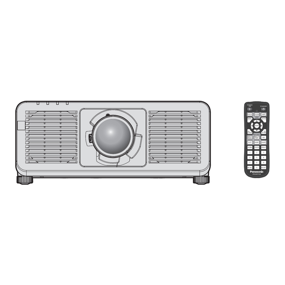
PT-REQ15
PT-REZ15
* PT‑REQ15 only
Resolution is 3 840 x 2 400 dots
(QUAD PIXEL DRIVE: ON)
ENGLISH
DPQP1489ZA/X1
Advertisement
Table of Contents


Need help?
Do you have a question about the PT-REQ15 and is the answer not in the manual?
Questions and answers