Table of Contents
Advertisement
Quick Links
Advertisement
Table of Contents

Subscribe to Our Youtube Channel
Related Manuals for SAB KR 175 Drake Antartica


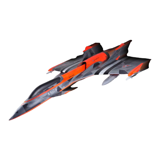
Summary of Contents for SAB KR 175 Drake Antartica
-
Page 3: Very Important
This is the only way to ensure that you are properly informed about changes to your kit, such as upgrades, retrofits and other important developments. SAB Avio cannot be held responsible for issues arising with your model and will not provide support unless you register your serial number. -
Page 4: Important Note
PRODUCT. THE PURCHASER ACKNOWLEDGES THAT THEY ALONE HAVE DETERMINED THAT THE PRODUCT WILL SUITABLY MEET THE REQUIREMENTS OF THE PURCHASER’S INTENDED USE. (c) Purchaser Remedy- SAB Avio’s sole obligation hereunder shall be that SAB Avio will, at its option, replace any Product determined by SAB Avio to be defective In the event of a defect, this is the Purchaser’s exclusive remedy. -
Page 5: Notes For Assembly
It is necessary to pay attention to the symbols listed below: Use Thread Locker Sand and fit where Medium Strength necessary ( SAB HA116-S) Important Indicates that for this assembly phase you need materials that are: Use Epoxy Glue Use CA Glue BAGxx BAG xxx. -
Page 6: Inside The Box
PACKAGING INSIDE THE BOX * Main fuselage * Front fuselage * Turbine Cover * Tank * Cone + exhaust pipe * Left Wings * Right Wings * Left Rudder * Right Rudder * Canopy * Left Canard * Right Canard * Vector * BAGS LIST LANDING GEAR DOORS... - Page 7 FUSELAGE CONNECTION BAG1 Connect the front part with the main Fuselage part. Align the two parts and tighten the screws. S0234 [HC184] If you decide to glue the 2 parts, ( best rigidity ) it need to sand the 2 joining surfaces. Socket Head Cap Screw Shoulder M4x30mm (HC559)
-
Page 8: Linkage Assembly
CANARD SERVO BAG2 Self Tapping SERVO ASSEMBLY Screw 3x12mm (HC549-S) It is suggested metal servo horn with M3 hole. Socket Head Cap NOTE: Uniball M3 Screw M3x6mm A 2mm hole is suggested (H0065-S) (HC044-S) 13-15mm Metal Servo Horn M3 Servo Spacer (H0075-S) SERVO Servo... - Page 9 CANARD INSTALLATION BAG2 Socket Head Cap LINKAGE Screws M4x15mm ASSEMBLED (HC103-S) Washer 16x1mm (HC230-S) Canard SX (S0201-S) CANARD SERVO SUPPORT ASSEMBLY Washer 16x1mm (HC230-S) Canard DX (S0202-S) NOTE: Look for the perfect aligment of the 2 canard. Page 7...
- Page 10 SERVO VECTOR ASSEMBLY BAG3 SERVO ASSEMBLY ...x2 Self Tapping Self Tapping It is suggested metal servo horn with M3 hole. Screw 3x12mm Screw 3x12mm (HC549-S) (HC549-S) NOTE: NOTE: 38-42mm A 2mm hole is suggested A 2mm hole is suggested Servo Spacer (H0075-S) Servo Spacer (H0075-S)
- Page 11 VECTOR BAG3 VECTOR LINKAGE ASSEMBLY Epoxy (eg. UHU plus) Epoxy (eg. UHU plus) Plastic Ball Link (H0403-S) Thread rod M3x97mm Carbon Rod 5x450mm Thread rod M3x97mm Metal uniball M3 NOTE: Nut M3 Please allow plenty of time for the glue to Linkage 1 cure before inserting plastic ball link onto Carbon Rod 450 Lenght ( Full Lengh Approx 536mm)
- Page 12 WING & RUDDER WIRE INSTALLATION NOTE: Protect properly all cables from contact with internal frames. Wing wire Rudder wire Wing wire Rudder wire Page 10...
- Page 13 SERVO VECTOR & LANDING GEAR WIRE NOTE: Protect properly all cables from contact with internal frames. Landing Gear Wire Servo Vector Wire Landing Gear Wire Servo Vector Wire Page 11...
- Page 14 TURBINE & FUEL WIRES NOTE: Protect properly all cables from contact with internal frames. Turbine Wire Fuel Pipe Page 12...
- Page 15 EXHAUST PIPE, CONE INSTALLATION BAG4 Fix the Tube 4/6mm inside the vector flange as shown in Figure 1. Hold in this position with the 2 Aluminum parts S0268. Drake Exhaust Pipe (S0076-S) CONE 4/6 mm (S0076-S) Alu Plate (S0268-S) Self Head Cap Screw M3x10mm (HC136-S) Page 13...
- Page 16 REAR LANDING GEAR RETRACT BOX Assembly instructions for SAB Landing Gear. LEFT REAR LANDING GEAR ASSEMBLY ALUMINUM LANDING GEAR BLOCK ASSEMBLY DRILL PATTERN LEFT REAR LANDING 40mm GEAR ASSEMBLY Socket head cap Wheel 82 screws M3x14mm (S0085-S) (HC064-S) Head cap screws...
-
Page 17: Front Landing Gear
FRONT LANDING GEAR FRONT LANDING GEAR ASSEMBLY RETRACT BOX Assembly instructions for SAB Landing Gear. FRONT RETRACT GROUP ASSEMBLED Socket head cap (S0085-S) FRONT LANDING Shoulder M3x20mm GEAR ASSEMBLY (HC082-S) Set Screws Socket head cap M4x6mm Shoulder M3x20mm (HC153-S) (HC082-S) - Page 18 CANOPY CLAMP INSTALLATION Socket Head Cap You can adjust the canopy Clamp plate for to get the perfect match with the canopy. Screws M3x10mm (HC056-S) Socket Head Cap Screws M3x10mm Washer (HC056-S) 3.2x 6x0.5mm [HC180] Canopy Clamp (S0230-S) NOTE Washer 3.2x 6x0.5mm [HC180]...
- Page 19 COMPONENTS SUPPORT BAG5 You can install your components on the 2 composite Plate. Self Tapping Screw 3x10mm (HC136-S) G10 Plate UAT Support (S0235-S) Self Tapping Screw 3x10mm (HC136-S) NOTE: You can glue a small piece of wood under the surface to inscrease the tightness of the screw.
- Page 20 COMPONENTS The Following drawing shows a typical installation. Page 18...
- Page 21 COMPONENTS Use the front area for install the batteries. It is suggested to use 1 battery for the turbine, 2 batteries for the RX system, and 1 battery for Landing Gear System. Make sure the batteries are locked in the defined position. Page 19...
-
Page 22: Tank Assembly
TANK ASSEMBLY BAG6 The Following drawing shows a typical solution for kerosene aspiration. NOTE: After preparing of the tank, check the absence of air leaks. Drake Tank (S0208-S) Breather Tigon Tube [M0038] Fuel Tube Brass Tube [HC564] Page 20... - Page 23 TANK ASSEMBLY BAG6 Socket head cap screws shoulder M4x40mm (HC560-S) Block Nut M4 (S0234-S) Main Tank Socket head cap screws shoulder M4x40mm (HC560-S) Block Nut M4 (S0234-S) Page 21...
- Page 24 TURBINE SUPPORT ASSEMBLY BAG7 Check the assembly centerdistance of your own turbine. Use this dimensions to define the drilling position of the aluminum support. Drill the red hole 5mm diameter. NOTE: We recommend installing the turbine the most forward as possible to optimaze the CG. Assembly Turbine To Turbine Support Position the turbine group and find the correct position to make the 4 holes 5mm.
-
Page 25: Installation Of The Turbine
INSTALLATION OF THE TURBINE BAG7 Glue the threaded nuts on the support. Socket Head Cap Screws M4x22mm It will be more easy to assembly / disassembly the turbine. (HC104-S) Block Nut M4 (S0234-S) Page 23... - Page 26 SERVO WING ASSEMBLY BAG8 Approx NOTE: Assembly 1 left and 1 right 25/30mm SERVO WING LEFT ASSEMBLED Thread lock M3x97mm Clevis M3 Metal servo horn with 2mm hole is suggested. Plastic Uniball M3 (S0230-S) (H0403-S) SERVO WING RIGHT ASSEMBLED SERVO WING ASSEMBLY SERVO LEFT WING ASSEMBLY SERVO RIGHT WING ASSEMBLY...
- Page 27 INSTALLATION SERVO WINGS BAG8 INSTALLATION LEFT SERVO WING INSTALLATION RIGHT SERVO WING Self Tapping Screws M3x10mm Self Tapping (HC136-S) Screws M3x10mm (HC136-S) RIGHT SERVO WING ASSEMBLED LEFT SERVO WING ASSEMBLED Socket Shoulder Metal Uniball M2.5x15mm (HC031-S) Nut M2.5 (HC200-S) Page 25...
- Page 28 SERVO RUDDERS ASSEMBLY BAG9 NOTE: Metal Servo Horn Suggested Assembly 1 left and 1 right Approx Plastic Uniball M3 21/25mm (H0403-S) Thread lock M3x55mm LEFT SERVO RUDDER ASSEMBLY 2mm Hole Approx 84mm Clevis M3 (S0230-S) RIGHT SERVO RUDDER ASSEMBLY SERVO RUDDER ASSEMBLY LEFT SERVO RUDDER ASSEMBLY RIGHT SERVO RUDDER ASSEMBLY...
- Page 29 INSTALLATION SERVO RUDDERS BAG9 LEFT RUDDER ASSEMBLY RIGHT RUDDER ASSEMBLY Drake Rudder SX Drake Rudder DX (S0212-S) (S0211-S) LEFT RUDDER SERVO RIGHT RUDDER SERVO ASSEMBLY ASSEMBLY Socket Head Cap Socket Head Cap Screws M2.5x15mm Screws M2.5x15mm (HC136-S) (HC136-S) Metal Uniball Flat Tapping Flat Tapping Metal Uniball...
-
Page 30: Wings Installation
WINGS INSTALLATION BAG10 To secure the 2 wings in position use the 2 knobs code HC561. RIGHT WING ASSEMBLED MAIN FUSELAGE ASSEMBLED LEFT WING ASSEMBLED Wing Knob (HC561-S) CF Washer Page 28... - Page 31 RUDDERS INSTALLATION BAG10 To secure the 2 Rudder in position use the 2 M3x16 screws. RIGHT RUDDER ASSEMBLED LEFT RUDDER ASSEMBLED Socket Head Cap Screws Shoulder M3x16mm (HC074-S) Page 29...
- Page 32 SET UP AILERON, ELEVATORS, CANARD SETUP Mix the canard rotation with elevator and vector deflection. When elevator go up, the vector go up and the canard should increase its incidence as in figure. Set minimum two flight conditions, indicated in table below. LOW SPEED CONDITION HIGH SPEED CONDITION Deflection...
-
Page 33: Rudder Setup
SET UP RUDDER SETUP Set up the rudder with +30mm external, -50 mm internal. The extra movment internal can be used for to create breake function. Mix the Rudder function with Vector function. Angle Exponential Angle Exponential RUDDER +30 / -30 / -20 VECTOR Page 31... - Page 34 SET UP BAG10 CANOPY Assemble the canopy by inserting the 4 screws in the appropriate canopy clamps. Drake Canopy It is possible to adjust the screws lenght for to get the best connection. (S0204-S) Ensure positioning with the M4 front screw as shown in the Figure. Socket Head Cap Screw M4x15mm (HC105-S)
-
Page 35: Center Of Gravity Position
SET UP CENTER OF GRAVITY POSITION Set the Battery in order to get the correct position of the Center of Gravity (CG) shown. The right CG position allow to fly with an excellent stability. If it is necessary add weight (lead) in the nose. RADIO TEST and PRE FLIGHT CHECK BEFORE ANY FLIGHT *Set up the remote control and the RX/Gyro system with care. - Page 36 REAR LANDING GEAR DOOR BAG11 Glue the G10 parts in the main landing gear box using epoxy. Cut the gearbox wall following the servo slot. If necessary adjust / sand the G10 parts until the door fit perfectly in the gear box. Drill Zone S0240-S Cut along the pre-cut and get 5 parts.
- Page 37 REAR LANDING GEAR DOOR BAG11 SERVO ASSEMBLY ...x2 LINKAGE ASSEMBLY ...x2 Uniball M2 (H0064-S) Plastic Uniball Head Screw M2.5x6 (H0066-S) (HC018-S) Approx 60mm Head Screw M2x6 Linkage M3x33mm (HC004-S) (H0237-S) Plastic Uniball (H0066-S) Mini Servo Glue the door along the central wall. Take care of the perfect alignment. Assemble following the drawing.
- Page 38 REAR LANDING GEAR DOOR BAG11 Drill the holes following the drawing Socket Screw quotes, if necessary widen the holes M3x30mm untile they match with fuselage holes. (HC090-S) S0242 CUT 1 32mm 15mm Self Screw M3x12mm (HC549-S) Washer M3 (H0007-S) S0242 CUT 2 21mm Spacer S0242 CUT 2...
- Page 39 FRONT LANDING GEAR DOOR BAG11 Glue the braket with epoxy in the position showed below. SERVO ASSEMBLY ...x1 LINKAGE ASSEMBLY ...x1 SERVO MOUNT ASSEMBLY Uniball M2 Head M2.5x6 (H0064-S) Front Servo Mount Linkage M3x33 Front landing (HC018-S) (H0237-S) gear door SERVO Uniball Uniball...
-
Page 40: Spare Parts
SPARE PARTS CANARD MECHANICAL SERVO WING SUPPORT SERVO RUDDER SUPPORT TURBINE SUPPORT (S0023-S) (S0041-S) (S0043-S) (S0119-S) - 1 x Canard Collar. - 1 x Collar Arm. - 2 x CF Servo wing support. - 2 x CF Servo rudder support. - 2 x Turbine Support. - Page 41 SPARE PARTS DRAKE TURBINE COVER DRAKE BOTTOM STABILAZERS DRAKE RUDDER DX DRAKE RUDDER SX (S0209-S) (S0210-S) (S0211-S) (S0212-S) - 1 x Drake Cover Turbine. - 1 x Drake Bottom Wing. - 1 x Drake Rudder DX. - 1 x Drake Rudder SX. DRAKE TANK TUBE SET VECTOR DRAKE INOX TUBE...
- Page 42 ACCESSORIES LANDING GEAR LEGS LANDING GEAR RETRACT GROUP LANDING GEAR WHEELS (S0083-S) (S0084-S) (S0085-S) - 1 x SET Landing Gear Legs. - 1 x SET Retract Group. - 1 x SET Landing Gear Wheels. WINGS TANK WITH PYLON WINGS ROCKETS WITH PYLON (S0075-S) (S0076-S) - 1 x SET Wings Tank With Pylons.
Need help?
Do you have a question about the KR 175 Drake Antartica and is the answer not in the manual?
Questions and answers