Table of Contents
Advertisement
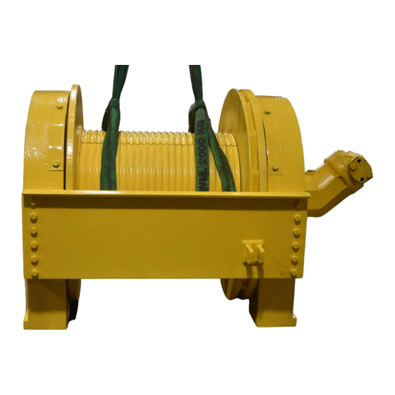
CH150A
CH175A
CH185A
CH230A
C2H150A
C2H175A
C2H185A
C2H230A
INSTALLATION, MAINTENANCE AND SERVICE MANUAL
PB-154
8/99
Printed in U.S.A.
2ND GENERATION
"CH" SERIES
PLANETARY HOISTS
BRADEN
PACR
P.O. BOX 547 BROKEN ARROW, OK U.S.A. 74013
PHONE (918) 251-8511 FAX (918) 259-1575
www.paccarwinch.com
WINCH DIVISION
Advertisement
Table of Contents

Subscribe to Our Youtube Channel
Related Manuals for BRADEN CH SERIES


Summary of Contents for BRADEN CH SERIES
- Page 1 BRADEN 2ND GENERATION “CH” SERIES PLANETARY HOISTS CH150A CH175A CH185A CH230A C2H150A C2H175A C2H185A C2H230A INSTALLATION, MAINTENANCE AND SERVICE MANUAL PACR WINCH DIVISION P.O. BOX 547 BROKEN ARROW, OK U.S.A. 74013 PB-154 PHONE (918) 251-8511 FAX (918) 259-1575 8/99 www.paccarwinch.com...
- Page 2 test...
-
Page 3: Table Of Contents
TABLE OF CONTENTS FOREWORD ..........2 GENERAL SAFETY RECOMMENDATIONS . -
Page 4: Foreword
The following service instructions have been prepared to provide assembly, disassembly and maintenance information for the BRADEN Model CH series winch. It is suggested that before doing any work on these units, all assembly and disas- sembly instructions should be read and understood. -
Page 5: General Safety Recommendations
17. Do not use knots to secure or attach wire rope. winch. 18. The BRADEN designed wire rope anchors are capable Be sure personnel are clear of work area BEFORE of supporting the rated load when installed properly. -
Page 6: Basic Operation
BASIC OPERATION DESCRIPTION OF HOIST The static brake system has three operating components: 1. Spring Applied, Multiple Friction Disc Static Brake The hoist is made up of the following sub-assemblies: 2. Brake Clutch Assembly Hydraulic motor and brake valve 3. Hydraulic Piston and Cylinder Drum, drum closure, ball bearings and oil seals Support end plate and bearing support Motor end plate and motor adapter... - Page 7 The static brake is released by the brake valve pilot pres- When lowering a load very slowly for precise positioning, no sure at a pressure lower than that required to open the pilot oil flow actually occurs through the winch motor. The pres- operated spool valve.
-
Page 8: Hoist Installation
10 and 90°F, use SAE 10W; for applications hoist should also be mounted perpendicular to an imaginary line colder than 10°F, contact the BRADEN Service Department. from the center of the drum to the first sheave to insure even The use of multi-viscosity oils is generally not recom- spooling. -
Page 9: Wire Rope Wedges
It is important that the wire rope have the proper tensioning ate loads, with reeving that let’s you place these loads on when it is installed on the drum. When the wire rope is first the block and the drum with all the rope off the drum except installed, you should operate the hoist, with light to moder- for the last three wraps. -
Page 10: Hydraulic Circuits
HYDRAULIC CIRCUITS SINGLE SPEED CIRCUIT 2 SPEED CIRCUIT WINCH ASSEMBLY W/BRAKE VALVE WINCH ASSEMBLY & STATIC BRAKE W/BRAKE VALVE & STATIC BRAKE BRAKE VALVE WINCH BRAKE BRAKE VALVE WINCH BRAKE 2-SPEED SELECTOR CONTROL CONTROL VALVE VALVE VALVE PUMP PUMP RECOMMENDED BOLT TORQUE The general purpose torque shown in the chart applies to SAE Grade 5 bolts, studs and standard steel full, thick and high nuts. -
Page 11: Preventive Maintenance
PREVENTIVE MAINTENANCE A regular program of preventive maintenance for your planetary winch is strongly recommended to minimize the need for emergency servicing and promote safe, reliable winch operation. Field experience, supported by engineering tests, indicate the three (3) service procedures listed below are the MOST critical to safe, reliable winch operation and must be observed. -
Page 12: Recommended Gear Oil
Awarm-up procedure is recommended at each start-up and is essential at ambient temperatures below +40°F (4°C). For simplicity, BRADEN has listed one (1) readily avail- able product in each temperature range which has The prime mover should be run at its lowest recommended been tested and found to meet our specifications. -
Page 13: Trouble Shooting
TROUBLE SHOOTING WARNING CAUTION If a winch ever exhibits any sign of erratic operation, or load control difficulties (i.e. load creeping or chattering) appro- priate troubleshooting tests and repairs should be performed immediately. Continued operation in this manner may result in property damage, serious personal injury or death. TROUBLE PROBABLE CAUSE REMEDY... - Page 14 TROUBLE PROBABLE CAUSE REMEDY Oil leaks from vent plug. 1. Same as A2. Same as A2. 2. Motor seal may be defective as a System back pressure must not result of high system back pres- exceed psi. Inspect sure or contaminated oil. hydraulic system for a restriction in the return line from the control valve to the reservoir.
- Page 15 TROUBLE PROBABLE CAUSE REMEDY “D” C Apply a stall pull load on the ROUBLE ONTINUED winch while monitoring pressure. REVIOUS Compare gauge reading to winch specifications. Adjust relief valve as required. NOTE: If pressure does not increase in proportion to adjustment, relief valve may be contaminated or worn out.
- Page 16 TROUBLE PROBABLE CAUSE REMEDY Winch “chatters” while raising rated Same as D2. Same as remedies for Trouble D2. load. Hydraulic oil flow to motor may be Same as remedies for Trouble E2. too low. Controls being operated too Conduct operator training as required. quickly.
-
Page 17: Hoist Disassembly
DISASSEMBLY PROCEDURE FOR HOIST 1. Remove the wire rope from the hoist drum and align 4. Begin the disassembly by standing the hoist on the the drain plug in the drum with the hole in the support end opposite the motor. Tag and remove the hydraulic end plate before removing the hoses and mounting hoses that connect the brake valve and the motor bolts. - Page 18 7. Remove the tee fitting from the brake cylinder nipple. 11. Remove the brake plate spacer and brake and friction discs. 8. Remove the eight (8) capscrews and lockwashers from the motor adapter, and remove the motor adapter. Remove and discard the O-ring that was under the motor adapter.
- Page 19 14. Remove the cable drum closure by using two (2) cap- screws from the motor adapter and a short piece of chain. Lift the closure out of the drum. Remove and 17. Remove the primary planet carrier assembly. Refer to discard the O-ring and the seal.
-
Page 20: Exploded View Drawing And Parts Key
22. Turn the drum over and remove and discard the seal. 20. Remove the output planet carrier assembly. You can Inspect the bearing in the end of drum. If replacement make hooks like the ones shown to make removal is necessary, use a bearing driver to remove the bear- easier. - Page 21 BRAKE CYLINDER SERVICE 3. Turn the brake cylinder on end with the large end up. Remove the spiral retaining ring and lift out the brake 1. Turn the brake cylinder on end with the large end piston plate. down. Use the special compression tool or a shop press to compress the backup plate in order to remove the retaining ring.
- Page 22 SECOND GENERATION CH SERIES EXPLODED VIEW AND PARTS KEY 1 0 1 1 0 2 1 0 0 1 3 7 1 3 6 1 2 9 1 3 5 1 4 0 1 3 3 A 1 4 1...
-
Page 23: Brake Cylinder Service And Assembly
ITEM DESCRIPTION QTY. ITEM DESCRIPTION QTY. Lockwasher Brake Cylinder Reducer Bushing Brake Piston Relief Valve Brake Piston Plate Sight Glass Backup Plate Pipe Plug Belleville Spring Motor End Plate Spring Guide Motor Adapter Retaining Ring O-Ring Snap Ring Capscrew Snap Ring Ring Gear O-Ring Ring Gear Adapter... - Page 24 BRAKE CYLINDER ASSEMBLY 5. Install the eight (8) belleville springs over the spring 1. Lubricate O-rings and backup rings with oil and install guide. The first one should rest against the snap ring them on the brake piston. The concave surface of the on the spring guide, with the concave side facing the backdrop ring must be next to the O-ring.
-
Page 25: Brake Cylinder Testing
7. Use a press or the special compression tool to com- 9. Now pressure check the brake cylinder assembly with press the springs. Make certain the threaded portion the hand pump connected to the 1/8” NPTF elbow in of the compression tool fully engages the lower plate. the top of the assembly. -
Page 26: Planet Carrier Service And Assembly
OUTPUT PLANET CARRIER SERVICE 3. To disassemble the primary planet carrier assembly, the steps are the same as for the output planet carrier assembly, except there is only one bearing for each gear. Also, the primary carrier has a thrust washer inside that can be removed after the planet gears are removed. - Page 27 OUTPUT PLANET CARRIER ASSEMBLY 1. Insert two bearings into a gear (when assembling the output planet carrier assembly for a CH150A, C2H150A, CH175A or C2H175A, install a bearing 3. Drive a spiral pin into place. Note that it is slightly spacer between the two bearings).
- Page 28 CLEAN AND INSPECT The thrust washer contact areas should be free from any surface irregularity that causes excessive abrasion or friction. Thoroughly clean all of the parts in a good grade of cleaning solvent; one that is not flammable, not toxic Finally, the shafts and carrier should be checked and will not cause skin rashes.
-
Page 29: Brake Clutch Service
BRAKE CLUTCH SERVICE DISASSEMBLY 4. Next, slide the sprag clutch out, inspect the sprag 1. Remove the snap ring and sprag bushing retainer from clutch closely for abnormal wear, cracks, pitting or cor- one end only. rosion. Check small clips for breakage or bright spots; the signs of excessive wear. - Page 30 6. Turn the assembly over with the snap ring down. Install the second retainer and snap ring. Make cer- 2. Turn the assembly over and install the sprag clutch in tain the snap ring is seated in the groove properly. the bore of the outer race.
-
Page 31: Hoist Assembly
HOIST ASSEMBLY 3. Turn the drum over, and set it down on the bearing support. Be careful not to damage the seal when low- ering the drum onto the bearing support. 1. Clean all parts before reassembling. The first step is to lay the support end plate down with the bearing support up. - Page 32 9. Install the ring gear adapter, hub end up, meshing the 6. Install the output sun gear and the thrust washer. adapter with the ring gear. Center the thrust washer on the output carrier so the primary carrier pilot can be installed in it. 10.
- Page 33 When installed correctly, the outer race should turn freely in the same direction as the drum turns to spool wire rope out. For most Braden assemblies, this will be clockwise as viewed from the motor end. 17. Measure the brake stack-up as shown. The measure- ment should be a minimum of 3/16”...
- Page 34 The long hose should point to the right as viewed from the motor end. 20. Install the motor adapter with eight (8) special 23. Lubricate and install a new O-ring around the pilot on BRADEN capscrews and lockwashers. the motor.
- Page 35 24. Engage the motor shaft in the brake clutch assembly 26. After the hoist assembly is complete, check all cap- inner race, and lower the motor into place. Install four screws and fittings to make certain they have been (4) capscrews and lockwashers tightened correctly.
-
Page 36: Reversing Direction Of Drum Rotation
This procedure applies in general terms to standard hoists with Commercial Intertech gear motors. For information concerning hoists with other types of motors, consult the BRADEN Service Department at the phone number listed in the FOREWORD section of this manual. - Page 37 6. Turn the sprag assembly around and slide the inner race (with 1 snap ring and bushing retainer) through the bushing and sprag clutch (the race will have to be ratated in the free-wheeling direction to start it through the sprag clutch). Install the remaining bushing retain- er and snap ring.
-
Page 38: Brake Valve Service
BRAKE VALVE SERVICE 1 1/2 INCH BRAKE VALVE Standard Braden second generation CH series hoists are supplied with one of two types of brake valves. Both are reliable hydraulic valves with internal componentsmanu- factured to close tolerances. Due to these close toler-... - Page 39 It is always a good practice to check the initial opening or “cracking” pressure of the brake valve whenever the hoist is serviced or inspected. Refer to Braden Service Bulletin 527 for complete brake valve test and adjustment proce- dures.
- Page 40 CLEAN AND INSPECT back-up ring is on the correct side of its O-ring. Take care not to cut the O-rings during assembly. Let the 1. Discard all O-rings and back-up rings. Clean all parts spool and piston set for ten (10) minutes before in solvent and blow dry.
-
Page 41: Metric Conversions
METRIC CONVERSION TABLE English to Metric Metric to English LINEAR inches (in.) X 25.4 = millimeters (mm) millimeters (mm) X 0.3937 = inches (in.) feet (ft.) X 0.3048 = meters (m) meters (m) X 3.281 = feet (ft.) miles (mi.) X 1.6093 = kilometers (km) kilometers (km) - Page 42 test...
- Page 43 test...
- Page 44 Copyright 2005 PACCAR Winch Division. All rights reserved.
Need help?
Do you have a question about the CH SERIES and is the answer not in the manual?
Questions and answers