Table of Contents
Advertisement
Quick Links
INSTALLATION, MAINTENANCE,
Visit our Web site at www.paccarwinch.com for the most comprehensive collection of winch, hoist, and drive
information on the Internet. Most publications and specification sheets are available for downloading.
LIT2718 R2
PB243
April 2017
Printe d in USA
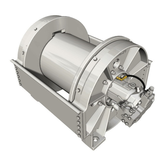
CH330 and CH400
HYDRAULIC WINCH
AND SERVICE MANUAL
WRITE HOIST SERIAL NUMBER BELOW
First 2 numbers indicate
year manufactured
For serial number location see page 4
1
CH330
CH400
©2017 PACCAR Inc.
All rights reserved
Advertisement
Table of Contents


Need help?
Do you have a question about the CH330 and is the answer not in the manual?
Questions and answers