Table of Contents

Related Manuals for BRADEN HP100B


Summary of Contents for BRADEN HP100B
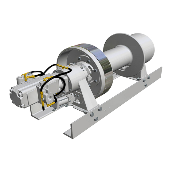
- Page 1 HP100B HYDRAULIC RECOVERY WINCH WRITE HOIST SERIAL NUMBER BELOW First 2 numbers indicate year manufactured For serial number location see page 4 INSTALLATION, MAINTENANCE, AND SERVICE MANUAL LIT2580 Rev 2 August 2015 Printed in USA...
-
Page 2: Table Of Contents
RECOMMENDED PLANETARY GEAR OIL ..............19 TROUBLESHOOTING ....................20 SERVICE PRECAUTIONS ..................23 RECOMMENDED BOLT TORQUE ................23 WINCH DISASSEMBLY ....................24 HP100B TOP LEVEL ASSEMBLY ................26 PRIMARY PLANETARY CARRIER SERVICE ............32 SECONDARY PLANET CARRIER SERVICE ............34 OUTPUT PLANET CARRIER SERVICE ..............36 OVERRUNNING CLUTCH SERVICE ...............38 MOTOR GROUP DIAGRAM ..................40... -
Page 3: Foreword
BRADEN provides parts and service through a network of BRADEN distributors. Parts and service are not available directly from the PACCAR Winch. For the name of your nearest BRADEN distributor, consult your local phone directory, or contact BRADEN as described above. -
Page 4: General Safety Recommendations
GENERAL SAFETY RECOMMENDATIONS Safety for operators and ground personnel is of prime con- 11. External clutches on recovery winches may disengage cern. Always take the necessary precautions to ensure the and drop or lose control of a load if they are NOT fully safety of others as well as yourself. - Page 5 27. NEVER allow anyone to stand or position any part of 30. ALL winch controls should be located within easy his or her body under a suspended load. reach of the operator. The controls shall be installed in such a location that the operator is removed from 28.
-
Page 6: Theory Of Operation
THEORY OF OPERATION BASIC DESCRIPTION valve that blocks the flow of oil out of the motor when the control valve is placed in neutral. With the control valve lever moved toward the pay-out direction, the spool valve The winch consists of the following sub-assemblies: remains closed until sufficient pilot pressure is applied to the end of the spool to shift it against the spring pressure 1. - Page 7 Figure 1 REELING-IN Static Brake Motor Figure 4 Static Friction Brake Applied Brake Valve Sprag Cams To Tank Pump Hoisting Control Valve High Medium Pressure Pressure Pressure Figure 2 Permits free shaft rotation while hoisting REEL-OUT - BEFORE BRAKE VALVE OPENS Static Brake Motor Brake Valve...
-
Page 8: Winch Installation
For conventional gear type motors, backpressure at ing of the winch. Braden recommends using a structure full flow should NOT exceed 100 PSI (690 kPa) for designed to be easily removed should the need arise to maximum motor shaft seal life. - Page 9 Maximum cold weather start-up viscosity should not ex- ceed 5000 SUS with a pour point of at least 20°F (11°C) lower than the minimum expected temperature. Under continuous operating conditions the temperature of the oil at any point in the system should not exceed 180°F (82°C).
-
Page 10: Hydraulic Circuit
TYPICAL HYDRAULIC CIRCUITS NOTE: The hydraulic circuits shown below are representative of typical HP100B winches with single and two-speed hydraulic motors and brake valves. Options and accessory equipment may result in changes to the circuits defined. If there are any questions regarding the hydraulic circuit, refer to the information supplied by the original equipment manufacturer, or contact the PACCAR Winch Technical Support Department, as previously defined. -
Page 11: Wire Rope Installation
WIRE ROPE INSTALLATION Winches are rated at bare drum line pull, meaning the maximum load capability will be reached on the first layer of wire rope. As the cable drum fills, the line pull will decrease (loss of leverage) as the line speed increases (larger circum- ference). -
Page 12: Pre-Delivery Checklist
PRE-DELIVERY CHECKLIST Before releasing the winch to the end user, the following checklist should be reviewed and each item verified. INSPECTION Check gear oil and refill as needed Lubricate all grease fittings Inspect winch mounting fasteners and torque as required Check for loose or missing bolts, pins, keepers, and cotter pins - replace as needed Check controls - adjustment and operation Verify winch operating pressure and flow... - Page 13 Securely attach the wire rope to the load in such a manner as to avoid damaging the load or rigging. Fully engage the drum clutch (see Drum Clutch Operation). When operating the winch in the pay-out direction, ALWAYS bring the load to a complete stop BEFORE Ensure the band brake is released and engage the winch attempting to shift the motor into high speed mode.
-
Page 14: Drum Clutch Operation
DRUM CLUTCH OPERATION Visually ensure that the drum clutch is fully engaged and To DISENGAGE the drum clutch: the clutch control lever is at full travel or locked in its de- tent BEFORE attempting to use the winch under load. 1. - Page 15 The Warning Label shown above is available through all Braden dealers. Have your dealer order part number 100600. It is a self-adhesive weather-resistant vinyl label that we recommend be installed near the winch controls of all Braden winches with a drum clutch.
-
Page 16: Auxiliary Rigging
AUXILIARY RIGGING Snatch Block Tree Protector An auxiliary sheave, or snatch block, may increase the If the wire rope or a snatch block must be anchored to a versatility of the winch, and is highly recommended in the tree or other structure for recovery purposes, a heavy ny- following applications: lon web sling of proper capacity rating should be used to avoid causing serious damage to the tree. -
Page 17: Preventive Maintenance
PREVENTIVE MAINTENANCE A regular program of preventive maintenance for your drum ends and clutch. On some winches, you will have winch is required to minimize the need for emergency ser- to disengage the clutch to gain access to the drum vicing and will promote safe, reliable winch operation. - Page 18 Inspection Interval Inspection Performed Daily Weekly Monthly Yearly Inspect wire rope and rigging Inspect drum clutch and shift mechanism for proper engagement Inspect for external oil leaks Check for damaged hoses / lines Check for loose or missing bolts, pins, keepers, or cotter pins Check gear oil level / refill Lubricate grease fittings Inspect breather fitting...
-
Page 19: Recommended Planetary Gear Oil
BRADEN has published the following specifications to assist in determining which lubricant is best suited to your application. For simplicity, BRADEN has listed available products in each temperature range that have been tested and found to meet our specifications. This is not to say that other lubricant brands would not perform equally as well. -
Page 20: Troubleshooting
TROUBLESHOOTING TROUBLE PROBABLE CAUSE REMEDY The winch will not reel-out the 1. The problem could be a plugged or Remove the pilot hose and fitting from the load or not reel-out the load loose pilot orifice. The pilot orifice brake valve, then use a 5/32 inch Allen smoothly. - Page 21 TROUBLE PROBABLE CAUSE REMEDY The brake will not hold a load 1. Excessive system back pressure The same as Remedy 2 of Trouble B2. with the control lever in neutral. acting on the brake release port. 2. Friction brake will not hold due to Same as Remedy 3 of Trouble A3.
- Page 22 TROUBLE PROBABLE CAUSE REMEDY The winch runs hot. 1. Same as D1. Same as remedies for Trouble D1. 2. Be certain that the hydraulic system temperature is not more than 180 degrees F. Excessive hydraulic oil temperatures may be caused by: A.
-
Page 23: Service Precautions
Work in a clean, dust free area as cleanliness is of utmost importance when servicing hydraulic equipment. Inspect all replacements parts, prior to installation, to detect any damage which might have occurred in shipment. Use only genuine BRADEN replacement parts for optimum results. Never re-use expendable parts such as o-rings and oil seals. -
Page 26: Hp100B Top Level Assembly
Remove the steel brake plates, friction discs, and brake plate spacer. 5. On the gearbox end of the winch, remove the cover The HP100B winch weighs approximately 1880 lbs (853 (40) by removing the capscrews (44). Remove the kg). Ensure all lifting equipment including the overhead thrust button (41) and thrust washer (42). - Page 27 9. Support the ring gear (12) with an overhead hoist. Re- move bolts (14) and remove the ring gear. The Drum weighs approximately 421 lbs (191 kg). En- sure all lifting equipment including the overhead hoist and rigging have adequate capacity. Use of lifting The Ring Gear weighs approximately 108 lbs (49 kg).
- Page 28 (19) using supplied brackets and capscrews (75), lock washers (48), and nuts (70). Install shifter fork (71) us- The HP100B winch weighs approximately 1880 lbs (853 ing shift fork pivot pin (72) and cotter pin (73). kg). Ensure all lifting equipment including the overhead hoist and rigging have adequate capacity.
- Page 29 24. Use the tapped holes (3/8 -16 UNC) in the post of the 34. Install drum spacer (25) on cable drum shaft (15). output planetary carrier assembly (500) to lift the out- put planet carrier assembly and install into the ring gear 35.
- Page 30 49. Install overrunning clutch (100) into the brake cylinder engaging the brake clutch inner race splines. Ensure proper orientation after installation by turning the brake clutch inner race in the COUNTER-CLOCKWISE di- rection before installing the motor. The drum should turn in the reel-in direction.
- Page 31 THIS PAGE INTENTIONALLY LEFT BLANK...
-
Page 32: Primary Planetary Carrier Service
PRIMARY PLANET CARRIER SERVICE DISASSEMBLY ITEM DESCRIPTION PRIMARY PLANET CARRIER PRIMARY PLANET GEAR PRIMARY PLANET PIN THRUST WASHER BEARING RETAINING RING 1. Remove the retaining ring (306) from one of the planet 3. Repeat the above steps for the remaining two planet carrier gears. - Page 33 ASSEMBLY 5. Place planet carrier in hydraulic press and provide sup- The loose roller bearings can be difficult to keep in place port around planet pin hole. Slowly press the knurled during assembly. This procedure is written to ease the as- surface of the planet pin into carrier until retaining ring sembly of the planet carriers.
-
Page 34: Secondary Planet Carrier Service
SECONDARY PLANET CARRIER SERVICE DISASSEMBLY ITEM DESCRIPTION SECONDARY PLANET CARRIER SECONDARY PLANET GEAR SNAP RING BEARING SPACER RETAINING RING SPACER 1. Remove the snap ring (403) from one of the planet car- 5. Thoroughly clean all parts and inspect for damage and rier posts. - Page 35 ASSEMBLY The loose roller bearings can be difficult to keep in place 4. Ensure the spacer (405) is in place in the planet carrier during assembly. This procedure attempts to simplify this. before installing gears on the planet carrier posts. 1.
-
Page 36: Output Planet Carrier Service
OUTPUT PLANET CARRIER SERVICE DISASSEMBLY ITEM DESCRIPTION OUTPUT PLANET CARRIER OUTPUT PLANET GEAR SNAP RING BEARING SPACER RETAINING RING SPACER 1. Remove the snap ring (503) from one of the planet car- 5. Thoroughly clean all parts and inspect for damage and rier posts. - Page 37 ASSEMBLY The loose roller bearings can be difficult to keep in place 5. Apply a light coat of grease the planet carrier bearing during assembly. This procedure attempts to simplify this. post and then slide the planet gear onto the planet car- rier post.
-
Page 38: Overrunning Clutch Service
OVERRUNNING CLUTCH SERVICE ITEM DESCRIPTION OUTER RACE RETAINING RING BALL BEARING OVERRUNNING CLUTCH RETAINING RING INNER RACE DISASSEMBLY NOTE: Outer race (item 142), Inner race (item 150) and Overrunning clutch (item 146) are NOT SOLD individually 1. Remove one of the retaining rings (item 147) from the as replacement parts. - Page 39 ASSEMBLY 14 TOOTH INTERNAL SPLINE Motor Input Spline Side Failure to assemble the overrunning clutch assembly with all parts oriented correctly may result in reduced brake effectiveness, which may lead to loss of load con- trol and result in property damage, injury or death. 1.
-
Page 40: Motor Group Diagram
HYDRAULIC MOTOR ASSEMBLY ITEM DESCRIPTION ITEM DESCRIPTION HYDRAULIC MOTOR - 2 SPEED HOSE -4 X 10 INCH (254 MM) BRAKE VALVE SWIVEL NUT 90 DEGREE ELBOW O-RING CAP NUT -4 JIC CAPSCREW 7/16-14 x 4-1/2 ASTM A574 HOSE -4 X 10 INCH (254 MM) SOCKET HEAD MANIFOLD LOCKWASHER 1/2 ZINC...
Need help?
Do you have a question about the HP100B and is the answer not in the manual?
Questions and answers