Table of Contents
Advertisement
Quick Links
Advertisement
Table of Contents

Related Manuals for IFM Electronic Efector 600 TADx91 Series


Summary of Contents for IFM Electronic Efector 600 TADx91 Series
- Page 1 Operating instructions Temperature transmitter TADx81 TADx91...
-
Page 2: Table Of Contents
Contents 1 Preliminary note ���������������������������������������������������������������������������������������������������3 1�1 Symbols used ������������������������������������������������������������������������������������������������3 2 Safety instructions �����������������������������������������������������������������������������������������������4 3 Functions and features ����������������������������������������������������������������������������������������4 3�1 Applications ���������������������������������������������������������������������������������������������������4 4 Functionality���������������������������������������������������������������������������������������������������������5 4�1 Communication, parameter setting, evaluation ���������������������������������������������5 4�2 Operating modes �������������������������������������������������������������������������������������������5 4�3 Monitoring and diagnostic functions ��������������������������������������������������������������6 4�3�1 Drift / fault monitoring ��������������������������������������������������������������������������6 4�3�2 Sensor backup / redundancy switching ������������������������������������������������6 4�4 Analogue function ������������������������������������������������������������������������������������������7 4�4�1 Behaviour in case of exceeding or not reaching the limits of the meas-... -
Page 3: Preliminary Note
7�2�6 Drift failure threshold �������������������������������������������������������������������������18 7�2�7 Definition of the switching characteristics of the diagnostic output �����18 7�2�8 Setting of the error behaviour of the analogue output ������������������������19 7�2�9 Setting of the characteristics of the redundancy switching �����������������19 7�2�10 Setting of the delay of the drift detection ������������������������������������������19 7�2�11 Set switching logic for OUT1 ������������������������������������������������������������19 7�2�12 Setting of the standard unit of measurement for temperature ����������19 7�2�13 Read error number ���������������������������������������������������������������������������19... -
Page 4: Safety Instructions
2 Safety instructions • Please read this document prior to set-up of the unit� Ensure that the product is suitable for your application without any restrictions� • If the operating instructions or the technical data are not adhered to, personal injury and/or damage to property can occur�... -
Page 5: Functionality
4 Functionality 4.1 Communication, parameter setting, evaluation • The unit generates output signals according to the parameter settings� • Using an IO-Link capable parameter setting tool such as the FDT service program ifm Container the following options are available: - Reading current process values� - Reading, changing and saving current parameter settings and transmitting them to other units of the same type�... -
Page 6: 4�3 Monitoring And Diagnostic Functions
4.3 Monitoring and diagnostic functions • By measuring with two different, thermically coupled sensor elements (NTC, PT 1000) the unit automatically detects drifts and errors during temperature measurement with great reliability� • An average value is formed from the measured individual NTC and Pt 1000 values�... -
Page 7: 4�4 Analogue Function
The behaviour of the unit, e�g�, in case of failure of one of the two measuring ele- ments is defined by the parameter [drEd] → 8 Operation. 4.4 Analogue function • [OU2] defines whether the set measuring range is provided as 4���20 mA ([OU2] = [I]) or as 20���4 mA ([OU2] = [InEG])� • The analogue start point [ASP] defines at which measured value the output signal is 4 mA (20 mA for [InEG])�... -
Page 8: 4�5 Operating Mode: 2-Wire Temperature Transmitter
- If the measured temperature falls any further, a message may be signalled to the controller depending on the setting of the menu item [drEd] (→ 8 Opera- tion)� 4.5 Operating mode: 2-wire temperature transmitter 4.5.1 Availability groups in 2-wire operation [drEd] Using [drEd] it can be set which recognised diagnosis types can be passed on via the current output (setting via FDT service program)�... -
Page 9: Output
4.6 Operating mode: 3-wire temperature transmitter with dia- gnostic switching output 4.6.1 Availability groups in 3-wire operation [drEd] Types of diagnostic to be signallled via the current or diagnostic switching output can be set using [drEd] (setting via FDT service program)� Since in 3-wire operation all diagnostic messages can be transferred via the switching output, the current output only leaves its process value trans- fer in case of a failure�... -
Page 10: 4�6�2 Switching Characteristics Output 1 In Case Of Diagnosis [Dou1]
4.6.2 Switching characteristics output 1 in case of diagnosis [dOU1] The behaviour of the diagnostic output OU1 is independent of the analogue output OU2 and can be configured as below: Table 4 Switching characteristics output 1 in case of diagnostics [dOU1] Normal* Warning... - Page 11 Table 5 Types of diagnosis Case of diagnosis Warning Alarm Failure Drift warning threshold [drW] ● exceeded (factory setting: 0�2 °C) Limit temperature internal elec- ● tronics exceeded (+90°C) Drift alarm threshold [drA] ex- ● ceeded (factory setting: 0�5 °C) Failure of one of the two sensor elements (interruption / short ●...
-
Page 12: Installation
5 Installation Before installing and removing the unit: Make sure that no pressure is ap- plied to the system and there is no medium in the pipe� Take into account possible dangers which may arise from extreme plant/medium tempera- tures� 5.1 Installation of units with G1 process connection The unit can be fixed to different process connections�... - Page 13 Use in hygienic areas to EHEDG ► Make sure that the sensors are integrated into the system in ac- cordance with EHEDG� • Recommended minimum insertion depth of the sensor into the me- dium: ≥ 25 mm.
-
Page 14: 5�2 Installation Of Units With G½ Process Connection
5.2 Installation of units with G½ process connection Installation in G½ adapter� (Alternative for Aseptoflex units: instal- lation in Aseptoflex Vario adapter�) ► Slightly grease the contact areas between the sensor and adapter using a lubricating paste which is suitable and approved for the application�... -
Page 15: Electrical Connection
6 Electrical connection The unit must be connected by a qualified electrician� The national and international regulations for the installation of electrical equipment must be adhered to� Voltage supply to EN 50178, SELV, PELV / "supply class 2" to cULus� ►... -
Page 16: Parameter Setting
7 Parameter setting On delivery, the sensor is ready for operation and can be used without any further parameter setting� If adjustment of the sensor is necessary, the parameters can be set before instal- lation and set-up of the unit or during running operation� If you change parameters during operation, this will influence the function of the plant�... -
Page 17: 7�1 Adjustable Parameters
7.1 Adjustable parameters Configuration of the analogue signal: 4���20 mA [I] or 20���4 mA [InEG]� Analogue start point for the system temperature: measured value at which 4 mA is provided (20 mA if [OU2] = [InEG])� Analogue end point for the system temperature: measured value at which 20 mA is provided (4 mA if [OU2] = [InEG])�... -
Page 18: 7�2�2 Scaling Of The Analogue Value
7.2.2 Scaling of the analogue value ► Select [ASP] and set the value at which 4 mA is provided� ► Select [AEP] and set the value at which 20 mA is provided� Minimum distance between ASP and AEP: 5 K� Step increment °C -25���155... -
Page 19: 7�2�8 Setting Of The Error Behaviour Of The Analogue Output
7.2.8 Setting of the error behaviour of the analogue output ► → 4.5.2 Setting of the analogue value in case of diagnosis [FOU2], table 7.2.9 Setting of the characteristics of the redundancy switching ► Select [drEd] and set the value: - For 2-wire operation (Ub- not connected): → 4.5.1 Availability groups in 2-wire operation [drEd], table 1 - For 3-wire operation (Ub- connected): → 4.6.1 Availability groups in 3-wire operation [drEd], table 3 7.2.10 Setting of the delay of the drift detection ►... -
Page 20: Operation
8 Operation When the supply voltage is applied the unit is in the Run mode with a power-on delay time of 8 s (= normal operating mode)� It carries out its measurement and evaluation functions and provides output signals according to the set parameters� 9 Troubleshooting In case of faults or anomalies: ►... - Page 21 Fnr Type of fault Corrective measures Detected sensor drift exceeds alarm Drift exceeds alarm threshold� level [drA] Temperature measurement with reduced accuracy possible� ► Replace the unit� ► Check whether the parameter [drA] is programmed correctly� Supply voltage outside the operating ►...
-
Page 22: Scale Drawing
10 Scale drawing 10.1 Units with G1 process connection (TAD*81) 50,4 M12 x1 Dimensions in mm TAD981 TAD081 TAD181 87�5 140�5 196�5 156�5 173�5... -
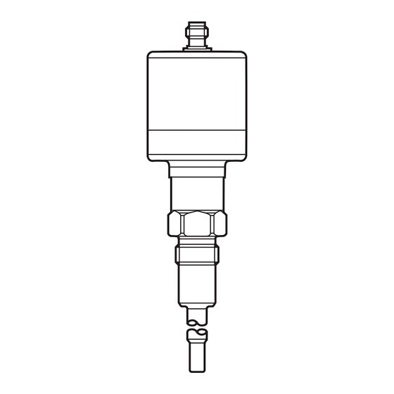
Page 23: 10�2 Units With G½ Process Connection (Tad*91)
10.2 Units with G½ process connection (TAD*91) 50,4 M12 x1 Dimensions in mm TAD991 TAD091 TAD191 87�5 68�5 85�5 106�5 123�5 231�5... -
Page 24: Technical Data
11 Technical data Measuring range[°C / °F] ������������������������������������������������������������������� -25���160 / -13���320 Operating voltage [V] ������������������������������������������������������������������������������������������� 18���32DC Current consumption in three-wire operation [mA] ����������������������������������������������� < 6 (24 V) Current rating [mA] ���������������������������������������������������������������������������������������������������������250 Short-circuit protection (pulsed); protected against reverse polarity and overload Integrated watchdog Analogue output ��������������������������������������������������������������������������������� 4���20 mA / 20���4 mA Max. load current output [Ω] ��������������������������������������������������������������������������... -
Page 25: 11�1 Temperature Resistance
11.1 Temperature resistance [min] [°C] Maximum operation time depending on the medium temperature 12 Factory setting Factory setting User setting 150.0 dOU1 FOU2 drEd Ondr °C More information at www�ifm�com...
Need help?
Do you have a question about the Efector 600 TADx91 Series and is the answer not in the manual?
Questions and answers