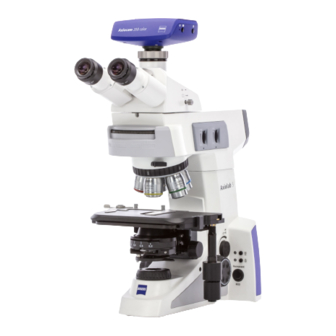
Zeiss Axiolab 5 Operating Manual
Upright microscope for routine and entry-level research
Hide thumbs
Also See for Axiolab 5:
- Quick reference manual (134 pages) ,
- Instruction manual (160 pages)

Related Manuals for Zeiss Axiolab 5


Summary of Contents for Zeiss Axiolab 5
- Page 1 Operating Manual Axiolab 5 Microscope for Routine and Entry-Level Research Upright Microscope for Routine and Entry-level Research...
- Page 2 Third party products are cited for information purposes only and this does not represent approval or recommendation of these products. Carl Zeiss Microscopy GmbH assumes no liability for the performance or use of such products. Published by Carl Zeiss Microscopy GmbH...
-
Page 3: Table Of Contents
Technical data ......................17 Interface diagram ......................20 Control and functional elements on the microscope..........21 2.4.1 Stand models ......................... 21 2.4.2 Axiolab 5 stand, Bio-TL ....................22 2.4.3 Axiolab 5 stand, Bio-TL/FL ....................24 2.4.4 Axiolab 5 stand, Pol-TL ....................26 2.4.5 Axiolab 5 stand, Pol-TL/conoscopy .................. - Page 4 ZEISS Contents / List of Illustrations Axiolab 5 3.1.8 Mounting the condenser ....................62 3.1.9 Mounting the darkfield condenser ................... 63 3.1.10 Mounting or replacing the 35 W halogen lamp or the 10 W LED illuminator for transmitted light ......................64 3.1.11...
- Page 5 System overview ....................... 132 LIST OF ILLUSTRATIONS Fig. 1-1 Warning labels on the Axiolab 5 stand for transmitted light and reflected light ....12 Fig. 1-2 Warning labels on the Axiolab 5 stand for transmitted light ..........13 Fig. 2-1 Interface diagram (Example: Axiolab 5 Mat-TL/RL stand) ............
- Page 6 ZEISS Contents / List of Illustrations Axiolab 5 Fig. 2-25 OSD menu, Home ......................50 Fig. 3-1 Setting up the microscope ....................51 Fig. 3-2 Placing tools in the storage compartment ................52 Fig. 3-3 Attaching the binocular tube ..................... 53 Fig.
- Page 7 Schematic diagram of the color charts developed by Michel-Lévy ........93 Fig. 4-10 Components for circular polarization contrast ..............96 Fig. 4-11 Axiolab 5 for transmitted light conoscopy ................98 Fig. 4-12 Determining optical character ..................100 Fig. 4-13 Components for transmitted light polarization on the conoscopy stand ......102 Fig.
-
Page 8: Introduction
Axiolab 5 INTRODUCTION Notes on instrument safety The Axiolab 5 microscopes were engineered, manufactured and tested in accordance with the DIN EN 61010-1 (IEC 61010-1) and IEC 61010-2-101 safety standards for electrical measuring, control and laboratory equipment. The microscopes fulfill the requirements as stated in Directive 98/79/EC on in vitro diagnostic medical devices (IVDD) and bear the marking. - Page 9 INTRODUCTION Axiolab 5 Notes on instrument safety ZEISS Axiolab 5 microscopes and their original accessories may be used only for the microscopy procedures described in this manual. Compliance with the following instructions is mandatory: CAUTION The microscope may only be plugged into an electrical outlet equipped with a safety contact.
- Page 10 INTRODUCTION ZEISS Notes on instrument safety Axiolab 5 CAUTION Operating the instrument in an area with a potentially explosive atmosphere is prohibited. It may be operated only on stable, non-flammable surfaces. Specimens must be disposed of appropriately in accordance with applicable statutory regulations and internal work instructions.
- Page 11 INTRODUCTION Axiolab 5 Notes on instrument safety ZEISS ATTENTION Always position equipment in a manner that permits easy disconnection from the power supply. ATTENTION Do not use a power supply cable with an inadequate rating. ATTENTION Closing or covering the ventilation slits may result in heat accumulation which could damage the instrument and even start a fire.
-
Page 12: Warning Labels On The Microscopes
Warning labels on the microscopes Axiolab 5 Warning labels on the microscopes NOTE Warning label: Hot surface! Affixed to all stands with transmitted light halogen illumination. Fig. 1-1 Warning labels on the Axiolab 5 stand for transmitted light and reflected light 430037-7444-001 05/2019... -
Page 13: Fig. 1-2 Warning Labels On The Axiolab 5 Stand For Transmitted Light
INTRODUCTION Axiolab 5 Warning labels on the microscopes ZEISS Fig. 1-2 Warning labels on the Axiolab 5 stand for transmitted light 05/2019 430037-7444-001... -
Page 14: Notes On The Warranty
No maintenance or repair work, except for the instances mentioned in the manual, may be performed on the microscopes. Only ZEISS service personnel or personnel authorized especially by ZEISS may perform repair work on the microscopes. Should your instrument malfunction, please contact the ZEISS Microscopy Service Department (see page 126) or the ZEISS agency assigned to your country. -
Page 15: Description Of The Instrument
Using a ZEISS Axiocam 202 mono or Axiocam 208 color camera, the microscope can be connected to an external HD monitor via an HDMI connection or to a PC/laptop via a USB connection to control camera functionality. - Page 16 DESCRIPTION OF THE INSTRUMENT ZEISS Intended use Axiolab 5 The ergonomic design elements of the microscopes include: − vertically adjustable, swivel-type and swivel/vertically adjustable ergo tubes − Latex free, skin-friendly surfaces on the binocular section of the tubes, control elements and stand −...
-
Page 17: Technical Data
− 10 mm to the viewing height of the upper limit for ergo tubes Weight Axiolab 5 microscope stand (depending on version and accessories) ......approx. 8 to 20 kg Ambient conditions Shipping (in packaging): Permissible ambient temperature ................... -40 to +70 °C Permissible humidity (without condensation) ............ - Page 18 DESCRIPTION OF THE INSTRUMENT ZEISS Technical data Axiolab 5 Light sources LED illumination with transmitted light/reflected light Power consumption ......................max. 10 W Adjustment of light source .............. continuous approx. 10 to 800 mA Halogen lighting with transmitted light/reflected light Power consumption ......................
- Page 19 DESCRIPTION OF THE INSTRUMENT Axiolab 5 Technical data ZEISS Viewing height and tube angle Order No. Binocular tube Viewing Adjustment Viewing angle height* in mm 425520-9000-000 Binocular tube 30°/23 30° - None - 449 / 485 425520-9010-000 Binocular photo tube 30°/23 (50:50) 30°...
-
Page 20: Interface Diagram
ZEISS Interface diagram Axiolab 5 Interface diagram The following figure shows a diagram of the interfaces of the microscope stand. The Axiolab 5 Mat-TL/RL stand is used here as an example. Fig. 2-1 Interface diagram (Example: Axiolab 5 Mat-TL/RL stand) -
Page 21: Control And Functional Elements On The Microscope
Control and functional elements on the microscope 2.4.1 Stand models Eight stand models are available in the delivery program: 1. Axiolab 5 stand, Bio-TL, XY stage with right handle (430037-9011-000) 2. Axiolab 5 stand, Bio-TL, XY stage with left handle (430037-9060-000) 3. -
Page 22: Axiolab 5 Stand, Bio-Tl
ZEISS Control and functional elements on the microscope Axiolab 5 2.4.2 Axiolab 5 stand, Bio-TL Transmitted light stand for bioscience (430037-9011-000) equipped with the following main components: 1. LED 10W-TL illuminator, optional with halogen reflector lamp 12 V 35 W 2. -
Page 23: Fig. 2-2 Axiolab 5 Stand, Bio-Tl
DESCRIPTION OF THE INSTRUMENT Axiolab 5 Control and functional elements on the microscope ZEISS Fig. 2-2 Axiolab 5 stand, Bio-TL 05/2019 430037-7444-001... -
Page 24: Axiolab 5 Stand, Bio-Tl/Fl
Control and functional elements on the microscope Axiolab 5 2.4.3 Axiolab 5 stand, Bio-TL/FL Transmitted light and reflected light fluorescence stand for bioscience (430037-9021-000) equipped with the following main components: 1. LED 10W-TL illumination, optional with halogen reflector lamp 12 V 35 W 2. -
Page 25: Fig. 2-3 Axiolab 5 Stand, Bio-Tl/Fl
DESCRIPTION OF THE INSTRUMENT Axiolab 5 Control and functional elements on the microscope ZEISS Fig. 2-3 Axiolab 5 stand, Bio-TL/FL 05/2019 430037-7444-001... -
Page 26: Axiolab 5 Stand, Pol-Tl
Control and functional elements on the microscope Axiolab 5 2.4.4 Axiolab 5 stand, Pol-TL Transmitted light stand for polarization (430037-9130-000) with the following main components: 1. LED 10W-TL illumination, optional with halogen reflector lamp 12 V 35 W 2. Nosepiece with 5 positions BF Pol (with 4x centerable, 1x fixed), coded 3. -
Page 27: Fig. 2-4 Axiolab 5 Stand, Pol-Tl
DESCRIPTION OF THE INSTRUMENT Axiolab 5 Control and functional elements on the microscope ZEISS Fig. 2-4 Axiolab 5 stand, Pol-TL 05/2019 430037-7444-001... -
Page 28: Axiolab 5 Stand, Pol-Tl/Conoscopy
ZEISS Control and functional elements on the microscope Axiolab 5 2.4.5 Axiolab 5 stand, Pol-TL/conoscopy Transmitted light stand for polarization/conoscopy (430037-9042-000) with the following main components: 1. LED 10W-TL illumination, optional with halogen reflector lamp 12 V 35 W 2. Nosepiece with 5 positions BF Pol (with 4x centerable, 1x fixed), coded 3. -
Page 29: Fig. 2-5 Axiolab 5 Stand, Pol-Tl/Conoscopy
Control and functional elements on the microscope ZEISS Fig. 2-5 Axiolab 5 stand, Pol-TL/Conoscopy ATTENTION The movements of rotary knobs A and BL (Fig. 2-5/9 and 10) and the respective setting wheels (Fig. 2-5/33 and 32) are coupled with each other. This means that only one control element should be operated at a time and the movement of the other should not be inhibited or blocked. -
Page 30: Axiolab 5 Stand, Pol-Tl/Rl
Control and functional elements on the microscope Axiolab 5 2.4.6 Axiolab 5 stand, Pol-TL/RL Transmitted light and reflected light stand for polarization (430037-9032-000) with the following main components: 1. LED 10W-TL illumination, optional with halogen reflector lamp 12 V 35 W 2. -
Page 31: Fig. 2-6 Axiolab 5 Stand, Pol-Tl/Rl
DESCRIPTION OF THE INSTRUMENT Axiolab 5 Control and functional elements on the microscope ZEISS Fig. 2-6 Axiolab 5 stand, Pol-TL/RL 05/2019 430037-7444-001... -
Page 32: Axiolab 5 Stand, Mat-Tl/Rl
Control and functional elements on the microscope Axiolab 5 2.4.7 Axiolab 5 stand, Mat-TL/RL Transmitted light and reflected light materials stand (430037-9052-000) with the following main components: 1. LED 10W-TL illumination, optional with halogen reflector lamp 12 V 35 W 2. -
Page 33: Fig. 2-7 Axiolab 5 Stand, Mat-Tl/Rl
DESCRIPTION OF THE INSTRUMENT Axiolab 5 Control and functional elements on the microscope ZEISS Fig. 2-7 Axiolab 5 stand, Mat-TL/RL 05/2019 430037-7444-001... -
Page 34: Functions Of Stands Keys And Display Elements
DESCRIPTION OF THE INSTRUMENT ZEISS Control and functional elements on the microscope Axiolab 5 2.4.8 Functions of stands keys and display elements For the location of the keys and display elements at your stand, refer to section 2.4.2 to 2.4.7. -
Page 35: Control And Functional Elements On Microscope Components
DESCRIPTION OF THE INSTRUMENT Axiolab 5 Control and functional elements on microscope components ZEISS Control and functional elements on microscope components 2.5.1 Binocular tubes/photo tubes The appropriate adapters for reflex cameras, microscope cameras and video cameras may be plugged into the camera port (Fig. 2-8/1, Fig. 2-9/1 or Fig. -
Page 36: Fig. 2-10 Binocular Photo Tube 30°/23 With Toggle Graduation 100:0/0:100
DESCRIPTION OF THE INSTRUMENT ZEISS Control and functional elements on microscope components Axiolab 5 Binocular photo tube 30°/23 (100:0/0:100) The light can be directed using a shift knob to either the eyepieces or the mounted camera. − Shift knob (Fig. 2-10/3) to front (eye symbol): 100% light to eyepieces. -
Page 37: Fig. 2-11 Binocular Ergo Photo Tube 20°/23 With Vertical Adjustment
Binocular ergo tube/ergo photo tube 20°/23 The ergo tube is designed for the 23 mm field of view. For use on the Axiolab 5 it is recommended for a maximum field of view of 22 mm. The viewing angle is 20°. -
Page 38: Microscope Stages
DESCRIPTION OF THE INSTRUMENT ZEISS Control and functional elements on microscope components Axiolab 5 2.5.2 Microscope stages Mechanical stage 75x50 R or L or mechanical stage 75x30 R ergonomic with stationary drive − Mechanical stage (Fig. 2-12/8) for holding and positioning specimens with a specimen holder. -
Page 39: Fig. 2-14 Mechanical Stage For Reflected Light 75X30 R With Specimen-Holding Plate
DESCRIPTION OF THE INSTRUMENT Axiolab 5 Control and functional elements on microscope components ZEISS Mechanical stage for reflected light 75x30 R − Mechanical stage (Fig. 2-14/2) for holding and positioning specimens with specimen holding plate (Fig. 2-14/1) with spring clips. -
Page 40: Filter Mount On Luminous-Field Diaphragm Operating Ring For Filter 32X4 Mm
DESCRIPTION OF THE INSTRUMENT ZEISS Control and functional elements on microscope components Axiolab 5 2.5.3 Filter mount on luminous-field diaphragm operating ring for filter 32x4 mm − Place the filter (Fig. 2-16/2) on the luminous- field diaphragm operating ring (Fig. 2-16/3). -
Page 41: Filter Slider For Reflected Light Stand
DESCRIPTION OF THE INSTRUMENT Axiolab 5 Control and functional elements on microscope components ZEISS 2.5.5 Filter slider for reflected light stand − Filter slider for reflected light with two positions for filters with a diameter of 25 mm (neutral and color filters, white balance filter) −... -
Page 42: Polarizer
DESCRIPTION OF THE INSTRUMENT ZEISS Control and functional elements on microscope components Axiolab 5 2.5.8 Polarizer Polarizer D, 90° rotatable, switchable (Fig. 2-21/3) − Polarizer can be swiveled in/out using handle (Fig. 2-21/1) − Polarizer with lever (Fig. 2-21/2), 90°... -
Page 43: Microscope Operating Modes
DESCRIPTION OF THE INSTRUMENT Axiolab 5 Control and functional elements on microscope components ZEISS 2.5.10 Microscope operating modes 2.5.10.1 Using the microscope imaging system as a standalone system The microscope with Axiocam 208/202 can be used in standalone mode. The camera acts as the control interface and is powered by microscope via the USB (Commercial Micro-D power) cable. - Page 44 Live images can be viewed on the monitor display and advanced features are available in OSD (on-screen display). With Axiolab 5 TL/FL, One-key fluorescence function can be used. Images can be snapped and saved into the USB Type-C drive, which is connected via the USB hub.
- Page 45 When a monitor is connected, live images can be viewed on the monitor display. Live images can also be viewed on PC or portable devices and advanced features in Labscope/Matscope are available. With Axiolab 5 TL/FL, the one-key fluorescence function can be used. Functionality: −...
- Page 46 When a monitor is connected, live images can be viewed on the monitor display. Live images can also be viewed on a PC or a portable device and advanced features in Labscope/Matscope are available. With Axiolab 5 TL/FL, the one-key fluorescence function can be used. Functionality: −...
- Page 47 DESCRIPTION OF THE INSTRUMENT Axiolab 5 Control and functional elements on microscope components ZEISS 2.5.10.5 Using the microscope imaging system with Labscope/Matscope via a USB connection The camera is powered by the microscope via a USB (Commercial Micro-D power) cable. An optional monitor can be connected to the camera via an HDMI cable.
- Page 48 DESCRIPTION OF THE INSTRUMENT ZEISS Control and functional elements on microscope components Axiolab 5 2.5.10.6 Using the microscope imaging system with ZEN software via a USB connection The camera is powered via a USB (Commercial Micro-D power) cable connected to an external power socket.
-
Page 49: Axiocam 202 Mono/208 Color Controls And Connectors
DESCRIPTION OF THE INSTRUMENT Axiolab 5 Control and functional elements on microscope components ZEISS 2.5.11 Axiocam 202 mono/208 color controls and connectors The camera connection panel contains the following connectors (see Fig. 2-23): port for power supply and communication to the microscope stand (via Commercial Micro-D cable) port for camera control and image transfer (USB 3.0) -
Page 50: Osd Functionality With Axiocam 202 Mono/208 Color
DESCRIPTION OF THE INSTRUMENT ZEISS Control and functional elements on microscope components Axiolab 5 2.5.12 OSD functionality with Axiocam 202 mono/208 color The On Screen Display menu (OSD menu) is shown on whatever display the camera is connected to via an HDMI cable. -
Page 51: Start-Up
START-UP The Axiolab 5 microscopes can be independently installed, converted and started up by the customer. On request, the microscope can also be installed or converted by ZEISS Service for an extra charge. NOTE Before installing and starting up the microscope, read the Notes on instrument safety (see section 1.1) carefully and thoroughly. - Page 52 START-UP ZEISS Mounting standard components Axiolab 5 • The tools (Fig. 3-2/1) required for set-up and adjustment of the microscope are located in the storage compartment (Fig. 3-2/2) at the back of the stand. • Pull the cover flap to open it, push it to close.
-
Page 53: Attaching The Binocular Tube/Photo Tube
Fig. 3-3 Attaching the binocular tube For tubes mounted with an intermediate plate on the Axiolab 5 stand, Pol-TL/conoscopy (430037- 90042-000), proceed as follows: • Loosen the screw (Fig. 3-3/6) with an Allen wrench (AF 3). Remove dust caps (Fig. 3-3/8, 11) from the underside of the tube and the dovetail ring mount on the stand side. -
Page 54: Inserting Eyepieces Or Auxiliary Microscope Or Pinhole Diaphragm
START-UP ZEISS Mounting standard components Axiolab 5 3.1.3 Inserting eyepieces or auxiliary microscope or pinhole diaphragm • Remove both dust caps (Fig. 3-4/1 and 5) from the binocular tube. • Remove both eyepieces (Fig. 3-4/2) from the box and insert them into the binocular tube to the stop. -
Page 55: Screwing In Objectives
(Fig. 3-5/R). NOTE The eyepiece reticles must be inserted under dust-free conditions. This should be carried out only by ZEISS Service. Inserting reversible eyecups The eyepieces have rubber protection rings to avoid scratches on the eyeglasses. These may be replaced by reversible eyecups as desired. -
Page 56: Inserting And Removing P&C Reflector Modules In/From The Reflector Turret
START-UP ZEISS Mounting standard components Axiolab 5 3.1.5 Inserting and removing P&C reflector modules in/from the reflector turret The reflector turret with four positions is firmly installed in the reflected light illumination module for fluorescence or materials stands. The modules must be inserted and removed from the front after removing the cover cap. -
Page 57: Mounting A Mechanical Stage
Mounting standard components ZEISS 3.1.6 Mounting a mechanical stage Axiolab 5 stands are fitted with the respective mechanical stage at the factory according to customer requirements. The friction adjustment of the coaxial knurled knobs is set at an average value at the factory. - Page 58 START-UP ZEISS Mounting standard components Axiolab 5 3.1.6.4 Friction adjustment of coaxial knurled knobs for X/Y adjustment of the mechanical stage (1) X drive • Push the coaxial knurled knob for the X adjustment (Fig. 3-9/4) all the way to the bottom.
-
Page 59: Mounting The Pol Rotary Stage
START-UP Axiolab 5 Mounting standard components ZEISS 3.1.7 Mounting the Pol rotary stage 3.1.7.1 Removing the Pol rotary stage • Loosen the screw cap (Fig. 3-10/6) from the spring housing (about three rotations). • Press the Pol rotary stage (Fig. 3-10/4) to the front against the spring-loaded pin (Fig. - Page 60 START-UP ZEISS Mounting standard components Axiolab 5 3.1.7.4 Removing the stage clips and mounting the detachable Pol specimen guide • Remove the stage clips (Fig. 3-10/9) from the Pol rotary stage. • Insert the Pol specimen guide (Fig. 3-10/2) with the two cylindrical pins on the underside into the holes provided (Fig.
- Page 61 START-UP Axiolab 5 Mounting standard components ZEISS 3.1.7.6 Centering the objectives of the polarization stand The nosepiece 5x Pol is equipped with one fixed and four centerable objective positions. Stage centering of the non-centering objective mount is necessary to ensure that a specimen feature located in the center of the field of view does not drift out while rotating the stage.
-
Page 62: Mounting The Condenser
START-UP ZEISS Mounting standard components Axiolab 5 3.1.8 Mounting the condenser • Move the stage carrier with the focusing drive to the higher stop position. ATTENTION The objectives should not collide with other parts. • Swivel out the front lens (if shiftable) on the condenser using the lever (Fig. -
Page 63: Mounting The Darkfield Condenser
START-UP Axiolab 5 Mounting standard components ZEISS 3.1.9 Mounting the darkfield condenser NOTE The condenser holder Z for darkfield is required to place darkfield condensers in the condenser carrier. • Insert the darkfield condenser (Fig. 3-14/6) in the condenser holder Z (Fig. 3-14/5) and screw on the fastening ring (Fig. -
Page 64: Mounting Or Replacing The 35 W Halogen Lamp Or The 10 W Led Illuminator For Transmitted Light
Mounting or replacing the 35 W halogen lamp or the 10 W LED illuminator for transmitted light Axiolab 5 stands are equipped with a 10W LED white light for transmitted illumination. The LED illuminator can be alternatively changed to a 35W Halogen lamp. - Page 65 START-UP Axiolab 5 Mounting standard components ZEISS Changing the LED illuminator • Press the loops (Fig. 3-17/1) on the securing clips of the lamp holder together and swing them out to the front. • Remove the LED illuminator plug (Fig. 3-17/2) from the connector of the stand.
- Page 66 START-UP ZEISS Mounting standard components Axiolab 5 Fig. 3-19 Inserting the LED illuminator • Insert the new LED illuminator with the adapter (Fig. 3-19/3) into the holding tube up to the stop. • Position the new LED illuminator with the pinhole (Fig. 3-19/5) at the top, or with the adapter lower front edge (Fig.
-
Page 67: Mounting Or Replacing The 35 W Halogen Lamp Or The 10 W Led Illuminator For Reflected Light
Mounting or replacing the 35 W halogen lamp or the 10 W LED illuminator for reflected light Axiolab 5 stands are equipped with a 10W LED white light for reflected illumination. The LED illuminator can be alternatively changed to a 35W Halogen lamp. - Page 68 START-UP ZEISS Mounting standard components Axiolab 5 Changing the LED illuminator • Press the loops (Fig. 3-22/1) on the securing clips of the lamp holder together and swing them out to the front. Fig. 3-22 Swinging the loops out • Remove the LED illuminator plug (Fig. 3-23/5) from the connector of the stand (Fig.
- Page 69 START-UP Axiolab 5 Mounting standard components ZEISS • Loosen the three side screws (Fig. 3-24/4a, 4b, 4c) with an Allen wrench (AF 2.5) (Fig. 3-24/3) and remove the old LED illuminator (Fig. 3-24/2) from the adapter (Fig. 3-24/1). • Insert the new LED illuminator into the adapter and tighten the three side screws on the adapter.
-
Page 70: Installing Or Replacing The Led Modules For Reflected Light Fluorescence
3.1.12 Installing or replacing the LED modules for reflected light fluorescence Axiolab 5 fluorescence stands can accommodate up to three fluorescence LED modules. To insert or replace the LED modules, proceed as follows. • Switch off the microscope, remove the power cord on the microscope and allow it to cool down at least 15 min. - Page 71 START-UP Axiolab 5 Mounting standard components ZEISS • Insert the new LED modules into the LED tube up to the stop. Ensure that the modules are inserted in ). the right holding positions (Fig. 3-26/ NOTE , The LED positions in Fig.
-
Page 72: Mounting The Axiocam 202 Mono Or Axiocam 208 Color
START-UP ZEISS Mounting standard components Axiolab 5 3.1.13 Mounting the Axiocam 202 mono or Axiocam 208 color • Mount the C-mount camera adapter (Fig. 3-27/2) on the Axiocam (Fig. 3-27/1). • Attach the Axiocam with the adapter to the camera port (Fig. 3-27/4) of the tube. -
Page 73: Mounting Optional Components
3.2.1 Mounting the light intensive co-observer unit The light-intensive co-observer unit is mounted on the Axiolab 5 with a main observer and one or two co- observers in accordance with the separate instructions for use for multi-conference facilities (order no. -
Page 74: Mounting And Centering The Low-Power System For The Objectives 2.5X/4X
START-UP ZEISS Mounting optional components Axiolab 5 3.2.3 Mounting and centering the low- power system for the objectives 2.5x/4x • If necessary, remove the polarizer or filter holder from the condenser carrier. • Hold the low-power system ( F ig. 3-29/4) parallel... -
Page 75: Inserting The Modulator Disk In The Condenser 0.9 Bf Pol
• Replace the condenser in its carrier (see section 3.1.8). Connecting to the power supply The power supply of the Axiolab 5 is located at the back of the instrument in all stand models. • Connect the microscope (Fig. 3-31/1) to the power supply via a power cord and mains socket. -
Page 76: Switching The Microscope On/Off
If Permanent mode is active: The illumination is continuously switched on. If ECO mode is active: The illumination switches off after 15 minutes without action. Only Axiolab 5 stand, Bio-TL/FL: • Select desired fluorescence application using the LED selection knob (Fig. -
Page 77: Using The Light Manager Function
START-UP Axiolab 5 Using the Light Manager function ZEISS Using the Light Manager function The Light Manager (LM) function saves the ratios of the set light intensities between different combinations of objective and reflector turret positions for a given light source. When changing the light intensity of one objective/reflector combination, the light intensities of other combinations will also change according to the set ratios. -
Page 78: Default Factory Settings Of The Microscope
START-UP ZEISS Default factory settings of the microscope Axiolab 5 Default factory settings of the microscope The default factory settings are: Light Manager enabled, but no light intensity values saved − Light intensity set to initial minimum value − all configuration stored will be cleared −... -
Page 79: Operation
(Fig. 4-2/A) or down (Fig. 4-2/B). This individual height adjustment in two stages (upper and lower position) is basically possible with all tubes of the Axiolab 5 program. The viewing height thus achieved depends on the selected inter-pupillary distance and the tube viewing angle, which may be stationary or variable, depending on the model. -
Page 80: Adjusting For Ametropia (User's Visual Impairment) When Using Eyepiece Reticles
OPERATION ZEISS Default setting of the microscope Axiolab 5 4.1.3 Adjusting for ametropia (user's visual impairment) when using eyepiece reticles The prerequisite for correct use of an eyepiece reticle is two adjustable eyepieces to compensate for different degrees of ametropia of the user. -
Page 81: Illumination And Contrast Methods In Transmitted Light
KÖHLER method". (2) Instrumentation for transmitted light brightfield microscopy The equipment of every Axiolab 5 microscope, except the stand for reflected light, permits the use of transmitted light brightfield microscopy. All available condensers, except special condensers such as darkfield condensers, can be used for transmitted light brightfield microscopy. - Page 82 OPERATION ZEISS Illumination and contrast methods in transmitted light Axiolab 5 • Close the luminous-field diaphragm (Fig. 4-3/5) until it is visible (even if not in focus) in the field of view (Fig. 4-3/A). • Turn the vertical control of the condenser drive...
- Page 83 OPERATION Axiolab 5 Illumination and contrast methods in transmitted light ZEISS (4) Setting the height stop on the condenser carrier • Loosen the fastening screw (Fig. 4-4/1) of the height stop using an Allen wrench (AF 3). • Use the focusing drive to focus on the specimen.
-
Page 84: Configuring Transmitted Light Darkfield Microscopy Using The Köhler Method
(2) Instrumentation All Axiolab 5 microscopes, except stands for reflected light, are suitable for darkfield applications. Condenser with darkfield stop in position D e.g.: − Condenser 0.9/1.25 H with modulator disk BF, DF, Ph 1, Ph 2, Ph 3 −... - Page 85 OPERATION Axiolab 5 Illumination and contrast methods in transmitted light ZEISS NOTE Since the apertures of objectives with an integrated aperture iris stop are too high for transmitted light darkfield microscopy, the aperture iris stop must at least be closed to the limit aperture of 0.65.
- Page 86 OPERATION ZEISS Illumination and contrast methods in transmitted light Axiolab 5 (5) Setting darkfield contrast with the immersion oil darkfield condenser • If necessary, swivel out the low-power system, polarizer or λ plate. • Move the condenser carrier down until the end stop.
-
Page 87: Configuring Transmitted Light Phase Contrast Microscopy
(2) Instrumentation All Axiolab 5 microscopes, except stands for reflected light, are suitable for phase contrast applications. − Phase contrast objectives with phase rings Ph 1, Ph 2 or Ph 3 for different average numerical apertures which can also be used in the brightfield. - Page 88 OPERATION ZEISS Illumination and contrast methods in transmitted light Axiolab 5 • If the overlap is not exact ( F ig. 4-6/A), the 6 3 2 H lighter annular diaphragm must be recentered with the aid of two Allen wrenches (AF 1.5) F ig.
-
Page 89: Configuring Transmitted Light Polarization Microscopy
The interference colors may be of the first or a higher order. (2) Instrumentation Polarization methods can be used in the transmitted light on Axiolab 5 microscopes for transmitted light polarization and conoscopy. − Strain-free objectives −... - Page 90 OPERATION ZEISS Illumination and contrast methods in transmitted light Axiolab 5 (3) Configuring the microscope • Configure the microscope as for transmitted light brightfield microscopy using the KÖHLER method (see section 4.2.1 (3)). • Center the Pol rotary stage (Fig. 4-7/1) (see section 3.1.7.5) and objectives (see section 3.1.7.6).
- Page 91 − Pol rotary stage (Fig. 4-7/1) − Polarizer D (rotatable or fixed) − Screw-in fixed analyzer slider D or lambda compensator or lambda/4 compensator combined with analyzer (in Axiolab 5 tubes) − Pol adjustment tool sample for polarization microscope (453679-0000-000) (3) Configuring the microscope •...
- Page 92 ZEISS Illumination and contrast methods in transmitted light Axiolab 5 • Remove the analyzer from the beam path and align the reticle along the split cracks of the sample. • Subsequently reinsert the analyzer and remove the Pol adjustment tool sample. The pass directions of the polarizer and analyzer will now be parallel to the reticle (Polarizer EW, Analyzer NS).
- Page 93 OPERATION Axiolab 5 Illumination and contrast methods in transmitted light ZEISS (4) Conclusions The gray-white color appearing first in the bright position above example (Fig. 4-8/1) corresponds to a path difference of 150 nm according to the Michel-Lévy color chart (Fig. 4-9).
- Page 94 OPERATION ZEISS Illumination and contrast methods in transmitted light Axiolab 5 4.2.4.3 Measuring path differences The measurement compensators are required for the exact measurement of path differences. These return, i.e. compensate, the path difference created by the specimen to zero (black of the first order).
- Page 95 − Circular polarizer D (no polarizers may be adapted on the condenser) including corresponding lambda/4 plate. − Stationary analyzer slider D or screw-in analyzer (in Axiolab 5 tubes). (3) Configuring the microscope • Set the microscope as for transmitted light brightfield microscopy using the KÖHLER method (see section 4.2.1).
- Page 96 ZEISS Illumination and contrast methods in transmitted light Axiolab 5 • Then swivel the upper part of the circular polarizer D (Fig. 4-10/4) into the beam path. • Rotate the lever of the lambda/4 plate of the circular polarizer D (Fig. 4-10/3) until maximum extinction is achieved (dark-gray field of view) (lever points 45°...
- Page 97 OPERATION Axiolab 5 Illumination and contrast methods in transmitted light ZEISS NOTE For a high-contrast image with higher-magnification objectives (from approx. 20x) the illumination aperture must be reduced to a value between 0.15 and 0.20, i.e. the aperture diaphragm must be closed accordingly.
-
Page 98: Configuring Transmitted Light Polarization With The Conoscopy Stand
Its main application is classic mineral microscopy. However, synthetic crystals, industrial minerals and plastics (e.g. films) can also be identified and characterized. (2) Instrumentation Conoscopic viewing is preferably carried out on the Axiolab 5 microscope for transmitted light conoscopy. − Strain-free objectives; recommended: N-Achroplan 50x/0.8 Pol objective or... - Page 99 OPERATION Axiolab 5 Illumination and contrast methods in transmitted light ZEISS • The polarization direction can be changed using the setting wheel (Fig. 4-11/4) of the analyzer. ATTENTION The movements of rotary knobs A and BL and the respective setting wheels are coupled with each other.
- Page 100 OPERATION ZEISS Illumination and contrast methods in transmitted light Axiolab 5 Inserting a lambda compensator (473704-0000-000) or lambda/4 (473714-0000-000) or a 0-4 lambda wedge compensator (000000-1140-663) in the compensator slot with the initial state of the axial figure being as illustrated in Fig. 4-12 results in the following changes in color (shown schematically as blue and yellow areas) to the axial figure, thus allowing differentiation in "optically positive"...
- Page 101 − Analyzer slider D − Lambda compensator or lambda/4 compensator NOTE The depolarizer is already incorporated in the Axiolab 5 stand for conoscopy. A depolarizer (quartz depolarizer) should be installed in all microscopes used for examining mineral/geological specimens. A depolarizer extinguishes undesirable polarization effects (e.g. false or pseudo-pleochroism) that may occur behind the analyzer (e.g.
- Page 102 OPERATION ZEISS Illumination and contrast methods in transmitted light Axiolab 5 (3) Configuring the microscope • Configure the microscope as for transmitted light brightfield microscopy using the KÖHLER method (see section 4.2.1 (3)). • Center the Pol rotary stage (Fig. 4-13/1) (see section 3.1.7.5) and objectives (see section 3.1.7.6).
- Page 103 OPERATION Axiolab 5 Illumination and contrast methods in transmitted light ZEISS 4.2.5.3 Determining the polarization direction n γ’ (1) Application The determination of the polarization direction of n or n respectively (polarization direction with the γ γ' absolute or relative largest index of refraction) and n...
- Page 104 ZEISS Illumination and contrast methods in transmitted light Axiolab 5 • Subsequently reinsert the analyzer slider and remove the Pol adjustment tool sample. The pass directions of the polarizer and analyzer will now be parallel to the crossline reticle (polarizer EW, analyzer NS).
- Page 105 OPERATION Axiolab 5 Illumination and contrast methods in transmitted light ZEISS (4) Conclusions The gray-white color appearing first in the bright position in the above example (Fig. 4-14/1) corresponds to a path difference of 150 nm according Michel-Lévy color chart (Fig.
- Page 106 OPERATION ZEISS Illumination and contrast methods in transmitted light Axiolab 5 The suitable compensator is determined as follows: • Configure the microscope as for transmitted light brightfield microscopy (see section 4.2.1), taking care to ensure the correct inter-pupillary distance in the binocular tube (see section 4.1.1).
- Page 107 OPERATION Axiolab 5 Illumination and contrast methods in transmitted light ZEISS 4.2.5.5 Circular polarization contrast with Axiolab for conoscopy (1) Application Unlike standard polarization contrast, circular polarization contrast does not show any dark (extinction) positions that depend on the angle of rotation (azimuth) of the specimen relative to the polarizer or analyzer.
- Page 108 OPERATION ZEISS Illumination and contrast methods in transmitted light Axiolab 5 6x20mm slider with lambda/4 plate Lower section of circular polarizer Lever for rotating the lambda/4 plate Lambda/4 plate in the upper part of the circular polarizer Adjustment slits Fig. 4-16 Components for circular polarization contrast on conoscopy stand •...
-
Page 109: Configuring Transmitted Light Polarization For Conoscopic Observation - Determining The Optical Character Of Crystals
Its main application is classic mineral microscopy. However, synthetic crystals, industrial minerals and plastics (e.g. films) can also be identified and characterized. (1) Instrumentation Conoscopic viewing is preferably carried out on the Axiolab 5 microscope for transmitted light conoscopy. − Strain-free objectives; recommended: N-Achroplan 50x/0.8 Pol objective or... - Page 110 • Place the specimen on the stage and focus on • Swivel the analyzer into the beam path (On Fig. 4-17 Axiolab 5 for transmitted light position) with rotary knob A (Fig. 4-17/2). The conoscopy polarization direction can be changed using the setting wheel (Fig.
- Page 111 OPERATION Axiolab 5 Illumination and contrast methods in transmitted light ZEISS The lines of this black cross remain closed when the stage is rotated. Depending on the section it may lie within or outside the displayed objective pupil. With optically biaxial crystals, the cross resolves into two dark hyperbola branches (the so-called isogyres) depending on stage rotation, which are surrounded by colored interference patterns depending on the amount of birefringence and specimen thickness (suggestive of the figure "8").
-
Page 112: Illumination And Contrast Methods In Reflected Light
OPERATION ZEISS Illumination and contrast methods in reflected light Axiolab 5 Illumination and contrast methods in reflected light 4.3.1 Configuring reflected light brightfield microscopy using the KÖHLER method (1) Application Reflected light brightfield microscopy is the simplest and most common optical microscopy method for examining opaque samples or specimens, e.g. - Page 113 OPERATION Axiolab 5 Illumination and contrast methods in reflected light ZEISS • For specimens with medium contrast characteristics, set the aperture diaphragm with the knurled wheel (Fig. 4-19/1) to between 2/3 and 4/5 of the exit pupil diameter of the objective.
-
Page 114: Configuring Reflected Light Darkfield Microscopy
All these light-scattering details light up brightly in the darkfield, whereas the even surface remains dark. (2) Instrumentation Observations in the reflected light darkfield can be made only on Axiolab 5 microscopes for reflected light. − Epiplan-Neofluar, EC Epiplan-Neofluar, Epiplan objectives with the additional designation “HD”... -
Page 115: Configuring Reflected Light Polarization - Proof Of Bireflectance And Reflexion Pleochroism
(Antiflex cap) permits the reflections to be eliminated even with "dark" specimen surfaces, which otherwise would be unavoidable. (2) Instrumentation Observations in the reflected light darkfield can be made only on Axiolab 5 microscopes for reflected light. − Pol rotary stage −... -
Page 116: Setting Reflected Light Fluorescence
The spectra of the excitation and the band-elimination filters must match very closely. They must be inserted in a reflector module FL P&C together with the respective dichroic beam splitter. Only powerful LEDs are supplied as FL excitation light sources in the Axiolab 5 program with the following options:... - Page 117 OPERATION Axiolab 5 Illumination and contrast methods in reflected light ZEISS (3) Configuring reflected light fluorescence The adjustment of reflected light fluorescence is facilitated by starting with an objective of average magnification, e.g. EC Plan-Neofluar 20x/0.50, and a specimen of high fluorescence. Demonstration samples can also be used for the start-up.
- Page 118 OPERATION ZEISS Illumination and contrast methods in reflected light Axiolab 5 LED selection knob for swiveling in the LED UV (385 nm) or LED B (475 nm) or LED G (555 nm) Nosepiece Intensity/LM knob Reflected light button (RL) Transmitted light button (TL)
-
Page 119: Care, Fuse Replacement And Service
ZEISS CARE, FUSE REPLACEMENT AND SERVICE Instrument care The only care required for the Axiolab 5 is as follows: • Switch the device off after each use and put the protective cover on (protects against dust and moisture). • Do not set the instrument up in a humid environment (max. humidity ≤ 75%). -
Page 120: Instrument Maintenance
CARE, FUSE REPLACEMENT AND SERVICE ZEISS Instrument maintenance Axiolab 5 Instrument maintenance 5.2.1 Checking the instrument • Ensure compliance with the specified line voltages. • Check the power cable and the plug for possible damage. • If any damage is observed, turn the instrument off and secure it against inadvertent restarts immediately. -
Page 121: Troubleshooting
CARE, FUSE REPLACEMENT AND SERVICE Axiolab 5 Troubleshooting ZEISS Troubleshooting 5.3.1 Microscope Problem Cause Solution No illumination light after Nosepiece and/or reflector turret are not Move the nosepiece and/or reflector switching on the microscope. engaged to defined positions. turret to the left or right to engage the nosepiece and/or reflector turret to defined positions. - Page 122 CARE, FUSE REPLACEMENT AND SERVICE ZEISS Troubleshooting Axiolab 5 Problem Cause Solution Asymmetric image sharpness, Condenser is not correctly adjusted. Adjust the condenser correctly; e.g. one side is sharp, one is see p. 81 ff. side blurred. Nosepiece is not engaged in its locking Engage the nosepiece in its locking position.
- Page 123 CARE, FUSE REPLACEMENT AND SERVICE Axiolab 5 Troubleshooting ZEISS Problem Cause Solution LED/halogen lamp does not Power plug is not plugged into the mains Insert the plug into the mains outlet. light up although the switch is outlet. Ensure that the outlet and instrument in the On position.
-
Page 124: Axiocam 202/208
CARE, FUSE REPLACEMENT AND SERVICE ZEISS Troubleshooting Axiolab 5 5.3.2 Axiocam 202/208 When the microscope is in use with Axiocam 202/208 Problem Cause Solution LED indicator is off. The camera is not drawing power via Make sure the microscope is powered the USB (Commercial Micro-D) cable. - Page 125 CARE, FUSE REPLACEMENT AND SERVICE Axiolab 5 Troubleshooting ZEISS Problem Cause Solution The image appears distorted on The image aspect ratio is 16:9. The Set the monitor aspect ratio to 16:9. the full-screen monitor. monitor may be set to a different aspect ratio and causes the distortion.
-
Page 126: Maintenance And Repair
Repairs of mechanical, optical or electronic components inside the instrument and electrical components of Axiolab 5 microscopes may be performed only by ZEISS service staff or specially authorized personnel. To ensure optimal configuration and trouble-free function of your microscope over a longer period of time, we recommend that you enter into a service/maintenance agreement with ZEISS. -
Page 127: Appendix
APPENDIX Axiolab 5 List of abbreviations ZEISS APPENDIX List of abbreviations Alternating current Automatic Component Recognition Width across flats B/BF Brightfield Bertrand lens Canadian Standards Association C DIC Differential Interference Contrast in circular polarized light Cover glass thickness D/DF Darkfield Diameter (e.g. - Page 128 APPENDIX ZEISS List of abbreviations Axiolab 5 Single Lens Reflex Slow (type of fuse) Total interference contrast in circular polarized light Transmitted light Underwriters Laboratories Ultraviolet Volt AC visual 430037-7444-001 05/2019...
-
Page 129: Index
Analyzer slider ..........................90, 91 Aperture diaphragm ......................30, 32, 40, 82 Auxiliary microscope ........................... 54 Axiocam ..........................43, 49, 72 Axiolab 5 stand, Bio-TL ........................22 Axiolab 5 stand, Bio-TL/FL ........................24 Axiolab 5 stand, Mat-TL/RL ......................... 32 Axiolab 5 stand, Pol-TL........................26 Axiolab 5 stand, Pol-TL/Conoscopy ...................... - Page 130 APPENDIX ZEISS Index Axiolab 5 Description of the instrument ......................15 Determining crystal character ....................... 98, 109 Diaphragm ............................88 Dimensions ............................17 Display elements ..........................34 Drive length ............................57 Ergo photo tube ..........................37 Ergo tube ............................37 Eyecups ..............................55 Eyeglass protection ring ........................55 Eyepiece reticle..........................54, 80 Eyepieces ......................
- Page 131 APPENDIX Axiolab 5 Index ZEISS Light sources ............................18 Low-power system ........................41, 74 Luminous-field diaphragm ................22, 24, 26, 28, 30, 32, 82 Maintenance ............................ 120 Materials stand ........................... 32 Mechanical stage ....................22, 24, 32, 38, 39, 57 Microscope stages ..........................
-
Page 132: Industrial Property Rights
APPENDIX ZEISS Industrial property rights Axiolab 5 Setting up ............................51 Slot ........................22, 24, 26, 28, 30, 32 Snap button ......................22, 24, 26, 28, 30, 32 Specimen guide ..........................39, 59 Specimen holder ........................... 38, 39 Specimen holding plate ........................39 Stage ..............................21... - Page 133 Schieber 12x46, mit fokussierbarer Bertrandlinse, 425145-9060-000 425145-9060-000 for phase contrast and conoscopy für Phasenkontrast und Konoskopie 453671-0000-000 453671-0000-000 Axiolab 5 stand, Bio-TL, Mikroskopstativ Axiolab 5, Axiolab 5 stand, Bio-TL/FL, Mikroskopstativ Axiolab 5, Axiolab 5 stand, Mat-TL/RL, Mikroskopstativ Axiolab 5, Mikroskopstativ Axiolab 5...
- Page 134 Objectives A-Plan M27 LED module 385 nm on W 0.8 H "0" (see price list) Not usable with: 423052-9593-000 000000-1095-168 Microscope stand Axiolab 5, Mat LED module 565 nm 430037-9052-000: 423052-9602-000 Lambda compensator, 6x20 Ultra condenser Dry darkfield condenser 473704-0000-000 1.2/1.4 (0.75-1.0)
Need help?
Do you have a question about the Axiolab 5 and is the answer not in the manual?
Questions and answers
Need instructions to remove stage for clearance to mount condenser on Axio lab 5
To remove the stage on a Zeiss Axiolab 5 to mount the condenser, follow these steps:
1. Loosen the screw cap from the spring housing by rotating it about three times.
2. Press the rotary stage forward against the spring-loaded pin.
3. Lift the stage off the stage carrier from the back and remove it upwards.
4. Re-tighten the screw cap.
These steps will allow you to remove the stage, providing access to mount the condenser.
This answer is automatically generated
how does one set up fluorescent microscopy in the axiolab 5
To set up fluorescent microscopy on the Zeiss Axiolab 5, follow these steps:
1. Prepare the Microscope
- Ensure the microscope is placed in a location with minimal vibration and away from direct sunlight to reduce scattered light interference.
2. Mount Standard Components
- Open the storage compartment at the back of the stand to access the necessary tools.
- Use the provided Allen wrenches to assemble and adjust components.
3. Attach the Binocular/Photo Tube
- Loosen the screw with an Allen wrench (AF 3).
- Remove dust caps from the tube and stand’s dovetail ring mount.
- Securely mount the binocular or photo tube.
4. Install Objectives for Fluorescence
- Use the appropriate objectives, such as N-Achroplan or EC Plan-Neofluar, depending on the model.
5. Set Up the Fluorescence Module
- Insert the fluorescence module into the microscope.
- Ensure the correct filter sets are installed for the desired fluorescence excitation.
6. Power and Calibration
- Unroll and connect the power cord.
- Turn on the LED fluorescence illumination.
- Adjust the phase contrast diaphragms as needed.
7. Image Capture (Optional)
- If using a camera (e.g., Axiocam 202 mono or Axiocam 208 color), connect it to the phototube.
- Adjust settings for image acquisition.
Once set up, the Axiolab 5 is ready for fluorescence microscopy without requiring a computer.
This answer is automatically generated