Advertisement
Available languages
Available languages
Quick Links
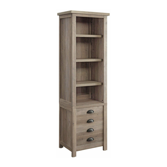
Modern Farmhouse Tower
If you have any questions regarding assembly or if parts are missing, DO NOT return this item to the
store where it was purchased. Please call our customer service number and have your instructions
and parts list ready to provide the model name, part name or factory number:
Pacific Standard Time: 8:30 a.m. - 4:30 p.m., Monday - Friday
Or visit our web site 24 hours a day, 7 days a week for product assistance at
THIS INSTRUCTION BOOKLET CONTAINS IMPORTANT SAFETY INFORMATION.
Stock # BH17-084-098-48
# BH17-084-099-97
ADULT ASSEMBLY REQUIRED
www.whalenstyle.com
Or e-mail your request to parts@whalenfurniture.com
PLEASE READ AND KEEP FOR FUTURE REFERENCE.
Date 2017-04-24 Rev. 0001-A Factory: KONRIC
866-942-5362
LOT NUMBER:
DATE PURCHASED:
/
/
Advertisement

Related Manuals for Better Homes and Gardens BH17-084-098-48


Summary of Contents for Better Homes and Gardens BH17-084-098-48
- Page 1 LOT NUMBER: DATE PURCHASED: Modern Farmhouse Tower Stock # BH17-084-098-48 # BH17-084-099-97 ADULT ASSEMBLY REQUIRED If you have any questions regarding assembly or if parts are missing, DO NOT return this item to the store where it was purchased. Please call our customer service number and have your instructions...
- Page 2 M A X I M U M R E C O M M E N D E D W E I G H T L O A D S MANUFACTURER: Whalen Furniture Manufacturing CATALOG: Modern Farmhouse Tower MODEL # BH17-084-098-48 / BH17-084-099-97 MADE IN CHINA MAXIMUM LOAD 50 lb. (22.6 kg) THIS UNIT IS INTENDED ONLY FOR USE WITHIN THE MAXIMUM WEIGHTS INDICATED.
- Page 3 IMPORTANT Before you begin: Open, identify and count all parts prior to assembly. Lay out parts on a flat and non- abrasive surface. You will need the parts identified on page 4 and 5 of this instruction manual. NOTE: IT IS VERY IMPORTANT TO USE GLUE WITH DOWELS. EXCESS GLUE CAN BE WIPED OFF WITH DAMP CLOTH.
- Page 4 Parts and Hardware List Please read completely through the instructions and verify that all listed parts and hardware are present before beginning assembly. A- Top Panel B- Left Upper Side Frame C- Right Upper Side Frame (Qty. 1) (Qty. 1) (Qty.
- Page 5 Parts and Hardware List Please read completely through the instructions and verify that all listed parts and hardware are present before beginning assembly. (1) Cam Lock (2) Cam Bolt (3) M8 x 30 mm Wood Dowel (Qty. 22+1 extra) (Qty. 22+1 extra) (Qty.
- Page 6 Assembly Instructions Cam Bolt (13 used in this step) ② 1. Unpack the unit and confirm that you have all the hardware and required parts listed. Assembly the unit on a carpeted floor or the empty carton to avoid any scratch. 2.
- Page 7 Assembly Instructions Door Stopper Cam Bolt M3.5 x 15 mm Flat Head Screw (1 used in this step) (9 used in this step) (2 used in this step) ② ⑤ ⑦ 3. Securely screw the Cam Bolts (2) into the designated small holes on the Fixed Shelf (D) at both sides. 4.
- Page 8 Assembly Instructions M4 x 38 mm Screw Wood Dowel (3 used in this step) (2 used in this step) ④ ③ 5. Insert two Wood Dowels (3) into the large holes on the front edge of Top Panel (A). Tap in with a rubber mallet, if necessary.
- Page 9 Assembly Instructions Cam Lock M8 x 30 mm Wood Dowel (1 used in this step) (2 used in this step) ① ③ 7. Attach the Bottom Front Stretcher (J) to the Bottom Panel (G) with two 30 mm Wood Dowels (3) and one Cam Lock (1).
- Page 10 Assembly Instructions Cam Lock Wood Dowel (6 used in this step) (6 used in this step) ① ③ 8. Attach the Bottom Panel assembly between the Lower Side Frames (E and F) with six 30 mm Wood Dowels (3) and six Cam Locks (1).
- Page 11 Assembly Instructions Cam Lock Wood Dowel (4 used in this step) (4 used in this step) ① ③ 9. Glue four Wood Dowels (3) into the top inner holes of the Lower Side Frames (E and F). 10. Position the Fixed Shelf (D) onto the inserted Wood Dowels (3) and attach it into place by engaging four Cam Locks (1).
- Page 12 Assembly Instructions Cam Lock Wood Dowel (2 used in this step) (2 used in this step) ① ③ 11. Attach the Middle Back Stretcher (I) between the Upper Side Frames (B and C) with two 30 mm Wood Dowels (3) and two Cam Locks (1).
- Page 13 Assembly Instructions Cam Lock Wood Dowel (5 used in this step) (6 used in this step) ① ③ 12. Combine the side frame assemblies together with six 30 mm Wood Dowels (3) and five Cam Locks (1).
- Page 14 Assembly Instructions Cam Lock Wood Dowel (4 used in this step) (4 used in this step) ① ③ 13. Glue four Wood Dowels (3) into the top inner holes of the Side Frames (B and C). 14. Position the Top Panel (A) onto the inserted Wood Dowels (3) and attach it into place by engaging four Cam Locks (1).
- Page 15 Assembly Instructions M3.5 x 15 mm Washer Head Screw (34 used in this step) ⑥ 15. Now, go back and securely tighten all the Cam Locks and Wood Screws. Make sure all the parts are tight and there are no gaps between the parts. This will help keep the unit square. 16.
- Page 16 Assembly Instructions #3 x 5/8” Zinc Screw (8 used in this step) ⑩ 17. Stand the assembled unit upright. 18. Pick up the Door Panel (M) and fasten the Hinge Bases to the hinge supports with four 5/8” Zinc Screws (10) in each. DO NOT fully tighten the screws.
- Page 17 Assembly Instructions Cam Lock Cover Shelf Pin (32 used in this step) (16 used in this step) ⑨ ⑧ 20. Insert the Shelf Pins (8) into the desired holes in the side frames (B, C, E and F). Make sure that you place the four Shelf Pins in the same level so the shelf is not tilted.
- Page 18 Assembly Instructions Tools required: Phillips screwdriver, power drill, 3/8” drill bit and rubber mallet. 22. Ask for assistance to position the tower at the desired location against a wall. If necessary, adjust the pre-attached floor levelers at the bottom of the tower to level the unit. Now, follow the instructions printed on the plastic bag containing the tipping restraint Hardware to attach the tip-over restraints to the unit and the wall.
-
Page 19: Care And Maintenance
Care and Maintenance Use a soft, clean cloth that will not scratch the surface when dusting. Use of furniture polish is not necessary. Should you choose to use polish, test first in an inconspicuous area. Using solvents of any kind on your furniture may damage your furniture’s finish. Never use water to clean your furniture as it may cause damage to the finish. - Page 21 NÚMERO de LOTE: FECHA de COMPRA: Torre Modern Farmhouse Serie # BH17-084-098-48 # BH17-084-099-97 ENSAMBLE REQUERIDO POR ADULTO Si tiene alguna pregunta acerca del ensamble o si alguna parte está faltante, no retorne este producto a la tienda que lo compró. Por favor llame a nuestro departamento de ayuda al cliente teniendo su instructivo y lista de partes para proveer el modelo, nombre de parte o el número de fábrica:...
- Page 22 M Á X I M O P E S O R E C O M E N D A D O FABRICANTE: Whalen Furniture Manufacturing CATÁLOGO: Torre Modern Farmhouse MODELO # BH17-084-098-48 / BH17-084-099-97 HECHO EN CHINA CARGA MÁXIMA 50 lb. (22.6 kg) ESTA UNIDAD DEBE UTILIZARSE CON LOS PESOS MÁXIMOS...
- Page 23 IMPORTANTE Antes de comenzar: Abra, identifique y cuente todas las partes antes del ensamble. Coloque las piezas sobre una superficie plana y no abrasiva. Tendrá que las partes identificadas en la página 4 de este manual de instrucciones NOTA: ES MUY IMPORTANTE PARA EL USO DE GOMA CON LOS PERNSO DE MADERA. EL. EXCESO DE PEGAMENTO SE PUEDE LIMPIAR CON UN PAÑO HÚMEDO.
- Page 24 Lista de partes y material de ferretería Por favor lea completamente las instrucciones y verifique que estén todas las partes antes de iniciar el ensamblado. A- Panel superior B- Marco lateral izquierdo superior C- Marco lateral derecho superior (Cant. 1) (Cant.
- Page 25 Lista de partes y material de ferretería Por favor lea completamente las instrucciones y verifique que estén todas las partes antes de iniciar el ensamblado. (1) Tuerca de fijación (2) Tornillo de fijación (3) Perno de madera de M8 x 30 mm (Cant.
- Page 26 Instructivo de ensamble Tornillo de fijación (13 usados en este paso) ② 1. Desempacar la unidad y confirmar que se tiene todo el material de ferretería y partes requeridas. Ensamblar la unidad en un piso alfombrado o en el cartón vacío para evitar rasguños. 2.
- Page 27 Instructivo de ensamble Tornillo de fijación Tornillo de cabeza plana de Tope de puerta M3.5 x 15 mm (9 usados en este paso) (1 usados en este paso) (2 usados en este paso) ② ⑤ ⑦ 3. Colocar los tornillos de fijación (2) en los agujeros chicos designados en la repisa fija (D) en ambos lados.
- Page 28 Instructivo de ensamble Tornillo de M4 x 38 mm Perno de madera (3 usados en este paso) (2 usados en este paso) ④ ③ 5. Insertar 2 pernos de madera (3) en los agujeros grandes en el borde frontal del panel superior (A). Golpear ligeramente con un mazo de goma, si es necesario.
- Page 29 Instructivo de ensamble Tuerca de fijación Perno de madera de M8 x 30 mm (1 usados en este paso) (2 usados en este paso) ① ③ 7. Adjuntar el soporte inferior frontal (J) al panel inferior (G) con 2 pernos de madera de 30 mm (3) y una tuerca de fijación (1).
- Page 30 Instructivo de ensamble Tuerca de fijación Perno de madera (6 usados en este paso) (6 usados en este paso) ① ③ 8. Adjuntar el ensamble del panel inferior entre los marco laterales inferiores (E y F) con 6 pernos de madera de 30 mm (3) y 6 tuercas de fijación (1).
- Page 31 Instructivo de ensamble Tuerca de fijación Perno de madera (4 usados en este paso) (4 usados en este paso) ① ③ Pegar con pegamento 4 pernos de madera (3) en los agujeros superiores internos de los marcos laterales inferiores (E y F). 10.
- Page 32 Instructivo de ensamble Tuercas de fijación Perno de madera (2 usados en este paso) (2 usados en este paso) ① ③ 11. Adjuntar el soporte posterior medio (I) entre los marcos laterales superiores (B y C) con 2 pernos de madera de 30 mm (3) y 2 tuercas de fijación (1).
- Page 33 Instructivo de ensamble Tuerca de fijación Perno de madera (5 usados en este paso) (6 usados en este paso) ① ③ 12. Combinar los ensambles de los marcos laterales con 6 pernos de madera de 30 mm (3) y 5 tuercas de fijación (1).
- Page 34 Instructivo de ensamble Tuerca de fijación Perno de madera (4 usados en este paso) (4 usados en este paso) ① ③ 13. Adjuntar con pegamento 4 pernos de madera (3) en los agujeros superiores internos de los marcos laterales (B y C). 14.
- Page 35 Instructivo de ensamble Tornillo cabeza de arandela de M3.5 x 15 mm (34 usados en este paso) ⑥ 15. Ahora, volver y apretar todas las tuercas de fijación y tornillos para madera. Asegurar que todas las partes esten apretadas y de que no hay huecos entre las partes, esto ayudara a mantener la unidad cuadrada.
- Page 36 Instructivo de ensamble Tornillo #3 x 5/8” zinc usados en este paso ⑩ 17. Poner la unidad ensamblada en posición vertical. 18. Levante el panel de la puerta (M) y sujete las bases de bisagra sobre con cuatro tornillos de 5/8” de zinc (10) en cada uno.
- Page 37 Instructivo de ensamble Tapa de la tuerca de fijación Perno de repisa (32 usados en este paso) (16 usados en este paso) ⑨ ⑧ 20. Insertar los pernos de repisa (8) en los agujeros deseados en los marcos laterales (B, C, E y F). Asegurar de poner los 4 pernos de repisa en el mismo nivel para que la repisa no esté...
- Page 38 Instructivo de ensamble Herramientas requeridas: Desarmador estrella, taladro, broca de 3/8” y mazo de goma. 22. Pida assistencia para posicionar la torre en el lugar deseado contra la pared. Si fuera necessario, ajuste los niveladores de piso pre-adjuntados en la parte inferior de la base para nivelar la unidad. Ahora, seguir las instrucciones impresas en la bolsa de plástico que contiene el juego de restricción de movimiento para adjuntar los topes de movimiento a la unidad y a la pared.
-
Page 39: Mantenimiento Y Cuidados
Mantenimiento y Cuidados Use una toalla suave y limpia para evitar daños y rayaduras. Uso de cera para pulir muebles no es necesario. Si desea usar cera, pruebela en un área que no sea visible para revisar su funcionamiento. Usar solventes de cualquier tipo puede dañar el acabado del mueble. Nunca use agua para limpiar la unidad, ya que le puede dañar el acabado.
Need help?
Do you have a question about the BH17-084-098-48 and is the answer not in the manual?
Questions and answers