Advertisement
Available languages
Available languages
Quick Links
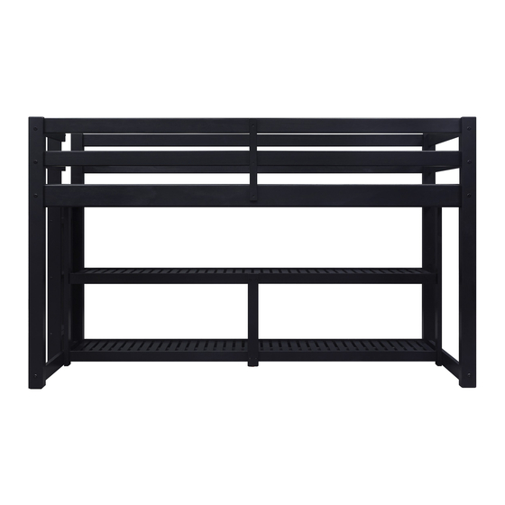
Greer Loft Storage Bed
Stock # BH17-084-097-45 Gray
If you have any questions regarding assembly or if parts are missing, DO NOT return this item to the
store where it was purchased. Please call our customer service number and have your instructions
and parts list ready to provide the model name, part name or factory number:
Pacific Standard Time: 8:30 a.m. - 4:30 p.m., Monday - Friday
Or visit our web site 24 hours a day, 7 days a week for product assistance at
THIS INSTRUCTION BOOKLET CONTAINS IMPORTANT SAFETY INFORMATION.
# BH17-084-098-45 Mocha
# BH17-084-098-46 White
# BHW-10018
# BHW-10019
ADULT ASSEMBLY REQUIRED
www.whalenstyle.com
Or e-mail your request to parts@whalenfurniture.com
PLEASE READ AND KEEP FOR FUTURE REFERENCE.
Date 2021-11-01
866-942-5362
Rev. 0001-B
LOT NUMBER:
DATE PURCHASED: /
Black
Natural
/
Advertisement

Subscribe to Our Youtube Channel
Related Manuals for Better Homes and Gardens Greer Loft BHW-10018


Summary of Contents for Better Homes and Gardens Greer Loft BHW-10018
- Page 1 LOT NUMBER: DATE PURCHASED: / Greer Loft Storage Bed Stock # BH17-084-097-45 Gray # BH17-084-098-45 Mocha # BH17-084-098-46 White # BHW-10018 Black # BHW-10019 Natural ADULT ASSEMBLY REQUIRED If you have any questions regarding assembly or if parts are missing, DO NOT return this item to the store where it was purchased.
- Page 2 ALWAYS USE GUARDRAILS ON BOTH LONG SIDES OF THE UPPER BUNK. IF THE BUNK BED WILL BE PLACED NEXT TO THE WALL, THE GUARDRAIL THAT RUNS THE FULL LENGTH OF THE BED SHOULD BE PLACED AGAINST THE WALL TO PREVENT ENTRAPMENT BETWEEN THE BED AND WALL. STRANGULATION HAZARD - Never attach or hang items to any part of the bunk bed that are not designed for use with the bed;...
- Page 3 TO HELP PREVENT SERIOUS OR FATAL INJURIES FROM ENTRAPMENT OR FALLS Follow the information on the warnings appearing on the upper bunk end structure and on the carton. Do not remove warning label from bed. Always use the recommended size mattress or mattress support, or both, to help prevent the likelihood of entrapment or falls.
- Page 4 Parts and Hardware List Please read completely through the instructions and verify that all listed parts and hardware are present before beginning assembly. A- Mattress Side Rail B- Guardrail C- Ventilated Shelf (Qty. 2) (Qty. 4) (Qty. 2) D- Headboard Front Post E- Headboard Back Post F- Footboard Front Post (Qty.
- Page 5 Parts and Hardware List Please read completely through the instructions and verify that all listed parts and hardware are present before beginning assembly. P- Left Ladder Support Q- Right Ladder Support R- Ladder Step (Qty. 1) (Qty. 1) (Qty. 3) S- Guardrail Support T- Shelf Support U- Mattress Support Slats...
- Page 6 ASSEMBLY OF THE HEADBOARD ⑤ ③ 1. Unpack the units and confirm that you have all hardware and required parts. 2. Insert the Wood Dowels (5) into the both end holes on the Headboard Rails (H, I and J) as a guide and attach the Headboard Front Post (D) to the Rails with four 100 mm Tapping Bolts (3).
- Page 7 ASSEMBLY OF THE HEADBOARD ② 4. Attach the Headboard Support (K) to the Rails (I and J) with four 32 mm Bolts (2).
- Page 8 ASSEMBLY OF THE LADDER ④ ⑤ 5. Insert the 50 mm Wood Dowels (5) into the large holes of Ladder Steps (R) at both ends. Attach Left and Right Ladder Supports (P and Q) to the Ladder Steps (R) using the 48 mm Tapping Bolts (4).
- Page 9 ASSEMBLY OF THE FOOTBOARD ③ ⑤ 6. Insert the Wood Dowels (5) into the both end holes on the Footboard Rails (M and N) as a guide and attach the Footboard Front Post (F) to the Rails with two 100 mm Tapping Bolts (3). 7.
- Page 10 ASSEMBLY OF THE FOOTBOARD ④ 8. Attach the assembly of the ladder to the Rails (M and N) with four 48 mm Tapping Bolts (4).
- Page 11 ASSEMBLY OF THE FOOTBOARD ⑤ ③ 9. Combine the Footboard Top Rails (L) with the Footboard Back Post (G) together with two 50 mm Wood Dowels (5) and two 100 mm Tapping Bolts (3).
- Page 12 ASSEMBLY OF THE FOOTBOARD ④ 10. Fasten the Footboard Top Rails (L) in place with two 48 mm Tapping Bolts (4).
- Page 13 ASSEMBLY OF THE FOOTBOARD ② 11. Attach the Footboard Support (O) to the Rails (M and N) with four 32 mm Bolts (2).
- Page 14 Assembly Instructions ② ⑤ 12. Attach two Ventilated Shelves (C) to the Footboard Support (O) and Front Post (F) with four 32 mm Bolts (2) and four 50 mm Wood Dowels (5).
- Page 15 Assembly Instructions ⑦ 13. Insert two Barrel Nuts (7) into the end of one Mattress Side Rail (A). 14. Attach the Mattress Side Rail (A) to the Footboard Front Post (F) using two 100 mm Bolts (1) through the drilled holes on the posts and screw into the Barrel Nuts (7).
- Page 16 Assembly Instructions ⑤ ③ 15. Attach two Guardrails (B) to the Footboard Front Post (F) with two 100 mm Tapping Bolts (3) and two 50 mm Wood Dowels (5).
- Page 17 Assembly Instructions ⑦ ② ⑤ ③ 16. Repeat steps 13 through 14 to attach the other Mattress Side Rail (A) to the Footboard Back Post (G). 17. Repeat steps 15 to attach the remaining Guardrails (B) to the Footboard Back Post (G). 18.
- Page 18 Assembly Instructions ② 19. Attach the Shelf Support (T) to the Ventilated Shelves (C) with four 32 mm Bolts (2).
- Page 19 Assembly Instructions ⑥ 20. With the pilot holes as a guide, align and attach the Guardrail Supports (S) to the center of both Guardrails (B) and the Mattress Side Rails (A) with 30 mm Screws (6).
- Page 20 Assembly Instructions ⑧ ⑧ 21. Lay out the Mattress Support Slats (U) onto the strips on the Mattress Side Rails (A). Make sure that the end slats located close to the Posts. Insert and screw the 35 mm Screws (8) into the countersunk holes on each slat.
-
Page 21: Quality Guarantee
Care and Maintenance Use a soft, clean cloth that will not scratch the surface when dusting. Use of furniture polish is not necessary. Should you choose to use polish, test first in an inconspicuous area. Using solvents of any kind on your furniture may damage the finish. ... - Page 23 NÚMERO de LOTE: FECHA de COMPRA: / Litera con area de almacenamiento Greer Serie # BH17-084-097-45 Gris # BH17-084-098-45 Moca # BH17-084-098-46 Blanco # BHW-10018 Negro # BHW-10019 Natural ENSAMBLE REQUERIDO POR ADULTO Si tienen alguna pregunta acerca del ensamble o si alguna parte está faltante, no retorne esté producto a la tienda donde lo compró.
- Page 24 SIEMPRE USAR LOS RIELES DE SEGURIDAD EN LOS 2 LADOS LARGOS DE LA LITERA SUPERIOR. SI LA LITERA SERA PUESTA CONTRA LA PARED, EL RIEL QUE CORRE LA LONGITUD COMPLETA DE LA LITERA DEBERA SER PUESTA CONTRA LA PARED PARA PREVENIR SER ATASCADO ENTRE LA LITERA Y LA PARED.
- Page 25 PARA AYUDAR A PREVENIR LESIONES SERIAS O FATALES POR ATASCAMIENTO O CAIDAS Siga la información en los avisos que aparecen en la estructura extrema de la litera superior y en el cartón. No retirar los avisos de la cama. ...
- Page 26 Lista de partes y material de ferretería Por favor lea completamente las instrucciones y verifique que estén todas las partes antes de iniciar el ensamblado. A- Riel lateral del colchón B- Riel de seguridad C- Repisa ventilada (Cant. 2) (Cant. 4) (Cant.
- Page 27 Lista de partes y material de ferretería Por favor lea completamente las instrucciones y verifique que estén todas las partes antes de iniciar el ensamblado. P- Soporte de escalera izquierdo Q- Soporte de escalera derecho R- Escalón (Cant. 1) (Cant. 1) (Cant.
- Page 28 ENSAMBLE DE LA CABECERA ⑤ ③ 1. Desempacar la unidad y confirmar que se tiene todo el material de ferretería y partes requeridas. 2. Insertar los pernos de madera (5) en ambos agujeros finales de los rieles de la cabecera (H, I y J) como guía y adjuntar el poste frontal de la cabecera (D) a los rieles con 4 tornillos de rosca de 100 mm (3).
- Page 29 ENSAMBLE DE LA CABECERA ② 4. Adjuntar el soporte de cabecera (K) a los rieles (I y J) con 4 tornillos de 32 mm (2).
- Page 30 ENSAMBLE DE LA ESCALERA ④ ⑤ 5. Insertar los pernos de madera de 50 mm (5) en los agujeros grandes de los escalones (R) en ambos lados. Adjuntar los soportes de escalera (P y Q) a los escalones (R) usando los tornillos de rosca de 48 mm (4).
- Page 31 ENSAMBLE DE LA PIECERA ③ ⑤ 6. Insertar los pernos de madera (5) en ambos agujeros finales de los rieles de piecera (M y N) como guía y adjuntar el poste frontal de la piecera (F) a los rieles con 2 tornillos de rosca de 100 mm (3). 7.
- Page 32 ENSAMBLE DE LA PIECERA ④ 8. Adjuntar la escalera ensamblada a los rieles (M y N) con 4 tornillos de rosca de 48 mm (4).
- Page 33 ENSAMBLE DE LA PIECERA ⑤ ③ 9. Combinar los rieles superiores de la piecera (L) con el poste posterior de la piecera (G) con 2 pernos de madera de 50 mm (5) y 2 tornillos de rosca de 100 mm (3).
- Page 34 ENSAMBLE DE LA PIECERA ④ 10. Sujetar los rieles superiores de la piecera (L) en su lugar con 2 tornillos de rosca de 48 mm (4).
- Page 35 ENSAMBLE DE LA PIECERA ② 11. Adjuntar el soporte de la piecera (O) a los rieles (M y N) con 4 tornillos de 32 mm (2).
- Page 36 Instructivo de ensamble ② ⑤ 12. Adjuntar 2 repisas ventilados (C) al soporte de la piecera (O) y al poste frontal de la piecera (F) con 4 tornillos de 32 mm (2) y con 4 pernos de madera de 50 mm (5).
- Page 37 Instructivo de ensamble ⑦ 13. Insertar 2 tuercas barril (7) en el extremo du uno de los rieles laterales del colchón (A). 14. Adjuntar el riel lateral del colchón (A) al poste frontal de la piecera (F) usando 2 tornillos de 100 mm (1) a través de los agujeros perforados en los postes y atornillar en las tuercas barril (7).
- Page 38 Instructivo de ensamble ⑤ ③ 15. Adjuntar 2 rieles de seguridad (B) al poste frontal de la piecera (F) con 2 tornillos de rosca de 100 mm (3) y 2 pernos de madera de 50 mm (5).
- Page 39 Instructivo de ensamble ⑦ ② ⑤ ③ Repetir los pasos 13 y 14 para adjuntar el otro riel lateral del colchón (A) al poste posterior de la piecera (G). 17. Repetir el paso 15 para adjuntar los rieles de seguridad (B) al poste posterior (G).
- Page 40 Instructivo de ensamble ② 19. Adjuntar el soporte de repisa (T) a los repisas ventilados (C) con 4 tornillos de 32 mm (2).
- Page 41 Instructivo de ensamble ⑥ 20. Usando los agujeros pilotos como guía, alinear y adjuntar los soportes del riel de seguridad (S) al centro de ambos rieles de seguridad (B) y a los rieles laterales del colchón (A) con tornillos de 30 mm (6).
- Page 42 Instructivo de ensamble ⑧ ⑧ 21. Descansar los soportes del colchón (U) en las tiras de los rieles laterales del colchón (A). Asegurar de que los soportes extremos esten cerca a los postes. Insertar y fijar los tornillos de 35 mm (8) en los agujeros avellanados en cada soporte.
-
Page 43: Mantenimiento Y Cuidados
Mantenimiento y Cuidados Use una toalla suave y limpia para evitar daños y rayaduras. Uso de cera para pulir muebles no es necesario. Si desea usar cera, pruebela en un área que no sea visible para revisar su funcionamiento. ...
Need help?
Do you have a question about the Greer Loft BHW-10018 and is the answer not in the manual?
Questions and answers