Azbil C15 Quick Reference Manual
Hide thumbs
Also See for C15:
- User's manual for installation & configuration (236 pages) ,
- User manual (150 pages)
Table of Contents
Advertisement
Quick Reference Guide
This guide offers a summary of key operations, parameter flowcharts, and settings, for convenient reference at
the operation site. This guide is made for repeated use. Dirt wipes off easily and even notes written with an oil-
based felt-tip pen can be removed with an eraser. If more detailed information on model C15 is needed, refer
to the user's manuals: CP-SP-1147E for basic operation and CP-SP-1148E for installation and configuration.
The most convenient way to configure the C15 is with the Smart Loader Package (model No. SLP-C35J50).
Please contact the azbil Group or a distributor for more information.
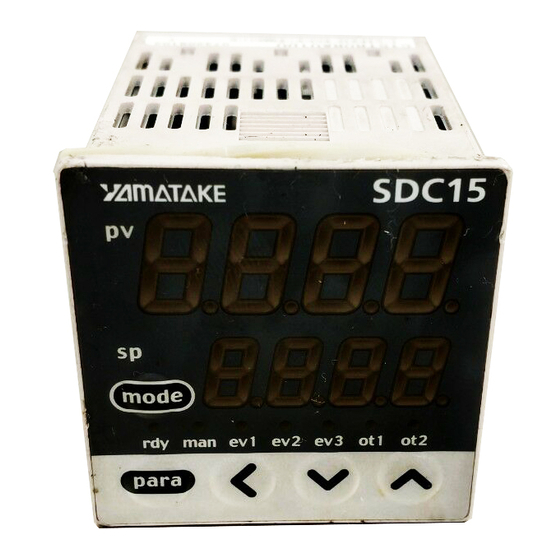
[mode] key
[para] key
Upper display
Lower display
Mode indicators
[mode] key
[para] key
[<], [ ] , [ ] keys
Loader connector
(Not for use in Japan)
This display shows either the PV value or the display value and set value for each displayed item. If an alarm is triggered, the
normal display and alarm code are displayed alternately. During auto tuning (AT), the rightmost decimal point flashes twice
repeatedly.
This display shows either the SP/MV/CT or the display value and set value for each displayed item. The rightmost decimal
point lights up or flashes to show RUN/READY mode or communications status, depending on the setting.
rdy:
Lights when READY (RUN mode if not lit)
man:
Lights when MANUAL (AUTO mode if not lit)
ev1, ev2, ev3: Lights when event relays are ON
ot1, ot2:
Lights when the control output is ON (always lit when the current output is used)
•
When this key is pressed and held for more than 1 second in the operation display mode, any of the following operations
from 0 to 7 which have been set previously can be executed:
0 : Mode key does not operate (Initial value)
1 : AUTO/MANUAL mode selection
2 : RUN/READY mode selection
3 : AT (Auto Tuning) start/stop selection
4 : LSP (Local SP) group selection
5 : Release all DO (Digital Output) latches
6 : Mode key does not operate
7 : ON/OFF selection of communication DI1
•
When pressing the [mode] key in the setup display mode, the display is changed to the operation display
•
This key is used to change the display item.
•
When this key is kept pressed for 2 s. or longer in the operation display mode, the display is then changed to the setup
display
Theses keys are used to increase or decrease the numeric value, or to shift the digit.
The Smart Loader connector is on the bottom of the C15. Use the dedicated cable that is included with the Smart Loader
Package to connect the controller to a PC.
for Model C15
Upper display
Indicators during AT
Lower display
Various indicators
Mode indicators
[ ], [ ], and [ ] keys
Loader connector (bottom panel)
1
CP-SP-1213E
: Initial value
Advertisement
Table of Contents

Subscribe to Our Youtube Channel
Related Manuals for Azbil C15


Summary of Contents for Azbil C15
- Page 1 Theses keys are used to increase or decrease the numeric value, or to shift the digit. Loader connector The Smart Loader connector is on the bottom of the C15. Use the dedicated cable that is included with the Smart Loader Package to connect the controller to a PC.
- Page 2 Flowchart of key operations and displays When the power is turned ON PV value LSP group Manipulated Heat manipulated Cool manipulated number variable variable variable SP value SP value MV value MV value MV value Timer remaining time 3 Upper and lower displays [para] key * Internal event 3 remain off for 6s after power...
- Page 3 Some items are not displayed depending on the availability of optional functions, model number, display setup ( ) and display level ( Pressing [para] key while changing settings has the effect of canceling and moving to the next item. ...
- Page 4 Operation examples letters : Items before operation Blue letters : Items during operation Execution of auto tuning (AT) Setup of PV input range type AT forces ON/OFF of the MV a number of times (a limit cycle) to cal- Press and hold [para] Start from the opera- culate PID values.
- Page 5 For step numbers indicated in red like , the following precaution applies: • If the key lock is set, the numerical value does not flash, and the value cannot be changed. To change a numerical value, cancel the key lock first. RUN/READY mode selection Setup of...
- Page 6 List of parameters : Essential parameters for PV measurement and control : Basic parameters : Required parameters when using optional functions List of operation displays [Extended tuning bank] Display Item Contents Initial value Setting value Display Item Contents Initial Setting AT type 0: Normal 1: Immediate response 2: Stable * Upper display: PV...
- Page 7 • Items marked in the tables are displayed in standard and/or high function configuration. • To change a user level, refer to Changing the user level in the lower right part of this page. [Lock bank] Display Item Contents Initial value Setting value User level 0: Simple configuration 1: Standard configuration...
- Page 8 2.04 or earlier, CT input failure ( ) is not displayed. AL 1 1 1-12-2 Kawana, Fujisawa Kanagawa 251-8522 Japan URL: https://www.azbil.com 1st edition: Mar. 2007 (W) © 2007–2019 Azbil Corporation. All Rights Reserved. 3rd edition: Apr. 2019 (B)
Need help?
Do you have a question about the C15 and is the answer not in the manual?
Questions and answers