Advertisement
Quick Links
CP-UM-5410EC
Single Loop Controller
User's Manual
"Installation"
Thank you for purchasing the C15M.
Before operating this product described in this User's Manual,
please take note of the following points regarding safety.
Be sure to keep this manual nearby for handy reference.
Please read the "Terms and Conditions" from the following URL
before ordering or use:
http://www.azbil.com/products/bi/order.html
NOTICE
Be sure that the user receives this manual before the product is
used.
Copying or duplicating this user's manual in part or in whole is
forbidden. The information and specifications in this manual are
subject to change without notice.
Considerable effort has been made to ensure that this manual is
free from inaccuracies and omissions. If you should find an error
or omission, please contact Azbil Corporation.
In no event is Azbil Corporation liable to anyone for any indirect,
special or consequential damages as a result of using this prod-
uct.
2006-2015 Azbil Corporation All Rights Reserved.
This manual explains handling precautions, mounting, wiring procedures,
PV range types, parameter list and main specifications only.
Unpacking
Check the following items when removing the C15MT from its package:
Name
Part No.
Mounting Bracket
81409651-001
Gasket
81409657-001
User's Manual
CP-UM-5410EC
(Not for use in Japan)
C15M
Q'ty
Remarks
1
1
1
This Manual
SAFETY PRECAUTIONS
WARNING
CAUTION
Note that incorrect wiring of the C15M can damage the C15M and
lead to other hazards. Check that the C15M has been correctly
wired before turning the power ON.
Before wiring, or removing/mounting the C15M, be sure to turn
the power OFF. Failure to do so might cause electric shock.
Do not touch electrically charged parts such as the power
terminals. Doing so might cause electric shock.
Do not disassemble the C15M.
Doing so might cause electric shock or faulty operation.
Use the C15M within the operating ranges recommended in the
specifications (temperature, humidity, voltage, vibration, shock,
mounting direction, atmosphere, etc.).
Failure to do so might cause fire or faulty operation.
Do not block ventilation holes.
Doing so might cause fire or faulty operation.
Wire the C15M properly according to predetermined standards.
Also wire the C15M using specified power leads according to
recognized installation methods.
Failure to do so might cause electric shock, fire or faulty operation.
Do not allow lead clippings, chips or water to enter the controller case.
Doing so might cause fire or faulty operation.
Firmly tighten the terminal screws at the torque listed in the
specifications. Insufficient tightening of terminal screws might
cause electric shock or fire.
Do not use unused terminals on the C15M as relay terminals.
Doing so might cause electric shock, fire or faulty operation.
We recommend attaching the terminal cover (sold separately)
after wiring the C15M.
Failure to do so might cause electric shock, fire or faulty operation.
Use the relays within the recommended service life.
Continuous use might cause fire or faulty operation.
If there is a risk of a power surge caused by lightning, use a surge
absorber (surge protector) to prevent fire or device failure.
Do not operate the keys with a propelling pencil or sharp-tipped
object. Doing so might cause faulty operation.
■ Location
Install the controller in the following locations:
· Common mode voltages for I/O excluding the power supply and relay
contact output: The voltage to ground is 30Vr.m.s max., 42.4V peak
max., and 60Vdc max.
· Not high or low temperature / humidity.
· Free from silicone gas and other corrosive gases such as sulfide gas.
· Less dust or soot.
· Appropriately processed locations to prevent direct sunlight, wind or rain.
· Less mechanical vibration and shock.
· Not close to the high voltage line, welding machine or electrical noise
generating source.
· The minimum 15 meters away from the high voltage ignition device for a
boiler.
· Less effect by the magnetic.
· No flammable liquid or gas.
· Indoors.
■ Mounting Procedure
· The mounting must be horizontal within 10 degrees tilted in back side
lowering or within 10 degrees tilted in back side rising.
· In the case of panel mount type (C15MT), the mounting panel should be
used with a thickness of less than 9 mm of firm board.
E1
Warnings are indicated when mishandling
this product might result in death or serious
injury to the user.
Cautions are indicated when mishandling
this product might result in minor injury to
the user, or only physical damage to this
product.
WARNING
CAUTION
Mounting
E1
Advertisement

Related Manuals for Azbil C15M


Summary of Contents for Azbil C15M
- Page 1 WARNING Be sure to keep this manual nearby for handy reference. Note that incorrect wiring of the C15M can damage the C15M and Please read the "Terms and Conditions" from the following URL lead to other hazards. Check that the C15M has been correctly wired before turning the power ON.
- Page 2 Caution RS-485 Communication Handling Precautions • Before wiring the C15M, verify the controller's model No. and terminal Nos. written on the label on the side of the body. Inspect all wiring once wiring work for the C15M has been completed.
-
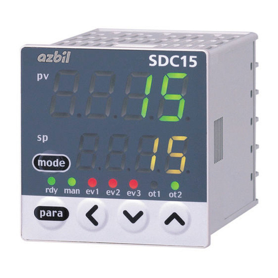
Page 3: Part Names And Functions
● PV Input range setup Part names and functions In the setup setting display mode [C01], press the [<] ] key • • to set the lower display to select a desired PV range type. SDC15 >> When no keys are pressed for 2 sec. or longer, the flashing of the numeric value is stopped to set the currently displayed value. -
Page 4: Maintenance
70.0Aac (800 turns, 1 time) Maintenance Formula; Number of turns ÷ (16 x number of power wire loops) x 1.4 Cleaning: When wiping out the C15M, use the soft and dried cloth. Display accuracy: ±5%FS Parts replacement: Do not replace the parts. Display resolution: 0.1Aac... - Page 5 User level details 0: Display in basic / standard / high function, C15M List of Parameters 1: Display in standard / high function, 2: Display in high function. [List of Operation Displays] Initial value may vary depending on model No.
- Page 6 CP-UM-5410EC [List of Setup Setting Displays] ■ Setup bank Bank selection: StUP Display Item Contents Initial User Display Item Contents Initial User value level value level PV input range Thermocouple (T): 1 to 6, 9 to 11, 13 to 21, 24, 25 CPL/MODBUS 0: CPL C 0 1...
- Page 7 ■ Event assignment bank Bank selection: EvCF Display Item Contents Initial User Display Item Contents Initial User value level value level E 1. C 1 to Operation type of 0: No event dI 1. 3 to Internal contact 0: Normally open (OFF, 0) 2 to 4 internal event 1 to 1: PV high limit...
- Page 8 Display Item Contents Initial User value level Ot 1. 6 to Control output 1 to Digits are called as 1st digit, 2nd digit, 3rd digit and 0000 2, event output 1 to 4th digit from the right end digit. Ot2. 6 Ev 1.
- Page 9 本机在通电前,请务必确认接线是否正确。 本机的接线或安装、拆卸时,请务必在切断电源的情况下进行。 中英文版的内容如有差异,以英文版为准。 请勿触摸电源端子等受电体。 要求 否则可能会触电。 请勿分解本机。 请确保把本使用说明书送到本产品使用者手中。 否则可能会触电及产生故障。 禁止擅自复印和转载全部或部分本使用说明书的内容。 今后内容变更时恕不事先通知。 本使用说明书的内容经过仔细审查校对,万一有错误和遗漏,请向本公司 注意 提出。 对客户应用结果,本公司有不能承担责任的场合,敬请谅解。 请在规格规定的使用条件(温度、湿度、电压、振动、冲击、安装 ©2006-2015 Azbil Corporation All Rights Reserved. 方向、环境等)范围内使用本机。 否则可能会引起火灾、产生故障。 请勿遮盖本机的通风口。 本书对使用上的注意事项和安装、接线、PV量程种类、参数一览、主要规 否则可能会引起火灾或产生故障。 格等进行说明。 请按照规定的基准、指定的电源及施工方法进行正确配线。 否则可能会引起火灾、触电、故障。 请确认 避免线头、切削粉、水等进入本机内部。 否则可能发生火灾、故障。 您购买的C15MT含有以下物品 81409651-001 1 个 安装件 请按照端子螺丝规格中记载的扭矩切实拧紧螺丝。...
- Page 10 设 置 接 线 ■ 安装场所 进行仪表电源配线时,请将本产品的主电源切断开关设置在操作员手能触 请把本机设置在如下场所。 及的范围内。 • 除供给电源及继电器接点输出外,输入输出模件的共模电压: 另外,进行AC电源型的仪表电源配线时,请配上滞后型(T)额定电流0.2A、 额定电压250V的保险丝。(IEC127) 对大地间的电压为30Vr.m.s.以下,峰值42.4以下,DC60V以下。 • 无高温﹑低温﹑高湿度﹑低湿度的场所。 仪表侧面的端子配列标号的含义如下表所示。 • 无硫化气等腐蚀性气体及硅气体的场所。 记 号 内 容 • 粉尘﹑油烟较少的场所。 ~ 交流 • 无直射阳光及风雨不能直接触及的场所。 注意、触电的危险 • 机械振动﹑冲击少的场所。 注意 • 远离高压线﹑焊接机附近及电气干扰发生源附近的场所。 • 远离如锅炉等有高压点火装置 15m 以上的场所。 使用上的注意事项 •...
- Page 11 ● PV输入量程的设定 各部件的名称和功能 设定显示「C01」下按[<]、[∨] 、[∧]键,在第2显示部上设定希望 的PV量程种类。 不需按键,只要经过2s以上时,闪烁将停止,PV量程种类的设定完 SDC15 成。 ① ● SP的设定 ② 运行显示的PV/SP显示中按[<]、[∨]、[∧]键, 变更第2显示部的 ④ mode SP。 ③ 不需按键,只要经过2s以上时,数值闪烁将停止,确定设定值。 para SP在参数设定显示下也可以设定。 PV量程表 ⑤ ⑥ ⑦ C01编号 C01 编号 传感器类型 量程 传感器类型 量程 ① 第1显示部: 显示PV值(现在的温度等)或设定项目。 Pt100 -200~+1200℃ -200~+500℃ ② 第2显示部: 显示SP值(设定温度值等)或各设定项目的设定...
- Page 12 型号构成表 : 19Vdc±15% 开路时电压 : 82Ω±0.5% 内部电阻 基本型号 安 装 控制输出 PV输入 电 源 选 项 语 言 规 格 : 24mAdc 以下(输出超过该值时,有可能损坏输 容许电流 C15M 出回路。) 盘安装型 最小OFF时间/ON时间 控制输出1(ot1) 控制输出2(ot2) : 时间比例周期小于10s时 1ms 继电器输出(NO) 继电器输出(NC) : 时间比例周期大于10s时 250ms 电压脉冲输出 无...
- Page 13 显示级别的含义 0:简单、标准、多功能显示, C15M参数一览表 1:标准、多功能显示 2:多功能显示 [ 运行显示一览表 ] 初始值有根据型号变化的情况。 ■ 运行显示 ■ PID 库 显 示 项 目 内 容 初始值 显示 级别 库选择 : PID SP (目标值) SP限幅下限(C07)~ 第1显示:PV SP限幅上限 (C08) 第2显示:SP 显 示 项 目 内 容 初始值...
- Page 14 1:加热MV (加热冷却控制用) 1:标准设定 2:冷却MV (加热冷却控制用) 2:多功能设定 3:PV 4:比率、偏置、滤波前PV LED监视 0:不使用 5:SP 1:RS-485通讯发送时闪烁 6:偏差(PV-SP) 2:RS-485通讯接收时闪烁 7:CT1电流值 3:全DI状态的OR(逻辑和) 8:CT2电流值 4:READY时闪烁 9:MFB (C15M时无效) CT1匝数 0: 800匝 10:SP+MV 1~40:CT的匝数除以100后的值 11:PV+MV CT1电力线貫通回数 0: 1回 控制输出1量程下限 -1999~+9999(小数点位置根据控 1~6: 回数 制输出1的种类变化) 100.0 控制输出1量程上限 CT2匝数 0: 800匝 1~40:CT的匝数除以100后的值...
- Page 15 ■ 事件组态库 库选择 : EVCF 显 示 项 目 内 容 初始值 显示 显 示 项 目 内 容 初始值 显示 级别 级别 0:无事件 0:常开 (OFF、0) 2~4 内部事件1~5 组态1 内部接点1~3 E1.C1 ~ dI1.3 ~ 1:PV上限 1:常闭 (ON、1) 动作种类 输入分配A E5.C1 dI3.3 2:PV下限...
- Page 16 显 示 项 目 内 容 初始值 显示 级别 0000 控制输出1~2、事件 输 从右侧开始1、2、3、4位 ot1.6 ~ 出1~3 反转A~D ot2.6 Ev1.6 ~ 0:不反转 第1位:反转A Ev3.6 1:反转 第2位:反转B 第3位:反转C 第4位:反转D 0:不反转 控制输出1~2、事件 ot1.7 ~ 1:反转 输出1~3 反转 ot2.7 Ev1.7 ~ Ev3.7 0:无 控制输出1~2、事件 输 ot1.8 ~...
Need help?
Do you have a question about the C15M and is the answer not in the manual?
Questions and answers