Page 1
INSTRUCTION MANUAL PIPE LASER TP-L5 SERIES TP-L5GV TP-L5G TP-L5BG For more information contact Synergy Positioning Systems or visit the Synergy Positioning Systems website at www.synergypositioning.co.nz TP-L5AV All branches: Phone 0800 867 266 Email: info@synergypositioning.co.nz
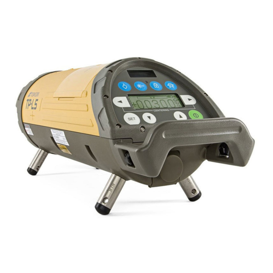
 TP-L5A 32956 90092 TP-L5B...
Page 3
“ STANDARD SYSTEM COMPONENTS” (p. iii) • The specifications and general appearance of the instrument are subject to change without prior notice and without obligation by Topcon Corporation and may differ from those appearing in this manual. • Some of the diagrams shown in this manual may be simplified for easier understanding.
Page 4
HOW TO READ THIS MANUAL Notes regarding manual style • Except where stated, "TP-L5" means TP-L5GV/G/BG/AV/A/B in this manual. • The specifications by the model are as follows. Auto alignment Upper/Lower Centerline Model Laser " Automatic alignment with the target Laser (TP-L5GV/G/AV/A only)"...
CONTENTS 1. PRECAUTIONS FOR SAFE OPERATION ................1 2. PRECAUTIONS ........................7 3. LASER SAFETY INFORMATION ..................13 4. PRODUCT OUTLINE ......................16 4.1 Parts and Functions of the Instrument................16 Control panel......................18 Key Operation (When the instrument is locked) ............21 ...
Page 7
CONTENTS 6.3 Setting Laser Line ......................36 Automatic Centering....................38 Automatic alignment with the target (TP-L5GV/G/AV/A only) ........39 6.4 Changing the laser beam mode..................42 7. STANDARD ACCESSORIES....................43 7.1 Self-centering Feet......................43 7.2 Single Point Foot......................44 7.3 Remote Controller (RC-200) ..................
1. PRECAUTIONS FOR SAFE OPERATION For the safe use of the product and prevention of injury to operators and other persons as well as prevention of property damage, items which should be observed are indicated by an exclamation point within a triangle used with WARNING and CAUTION statements in this instruction manual.
Page 10
1. PRECAUTIONS FOR SAFE OPERATION General Warning Do not use the unit in areas exposed to high amounts of dust or ash, in areas where there is inadequate ventilation, or near combustible materials. An explosion could occur. Do not perform disassembly or rebuilding. Fire, electric shock, burns or hazardous radiation exposure could result.
Page 11
1. PRECAUTIONS FOR SAFE OPERATION Caution Do not use the carrying case as a footstool. The case is slippery and unstable so a person could slip and fall off it. Do not place the instrument in a case with a damaged case or belt. The case or instrument could be dropped and cause injury.
Page 12
1. PRECAUTIONS FOR SAFE OPERATION Do not use batteries other than those designated. An explosion could occur, or abnormal heat generated, leading to fire. Do not use damaged power cords, plugs or loose outlets. Fire or electric shock could result. Do not use power cords other than those designated.
Page 13
1. PRECAUTIONS FOR SAFE OPERATION Do not use batteries or the battery charger if wet. Resultant shorting could lead to fire or burns. Do not connect or disconnect power supply plugs with wet hands. Electric shock could result. Caution Do not touch liquid leaking from batteries. Harmful chemicals could cause burns or blisters.
Page 14
1. PRECAUTIONS FOR SAFE OPERATION Do not carry the tripod with the tripod shoes pointed at other persons. A person could be injured if struck by the tripod shoes. Keep hands and feet away from the tripod shoes when fixing the tripod in the ground.
2. PRECAUTIONS Before starting work or operation, be sure to check that the instrument is functioning correctly with normal performance. Charging Battery • Be sure to charge the battery within the charging temperature range. Charging temperature range: 10 to 35 °C Warranty policy for Battery •...
Page 16
2. PRECAUTIONS Storage precautions • When storing the instrument, keep it in a place not exposed to direct sunlight and at the temperature range from -30 to 60°C. • Do not store the wet instrument in the carrying case. If any part of the instrument is wet, thoroughly wipe off with soft cloth and leave it dry before storing in the carrying case.
Page 17
2. PRECAUTIONS Measurement This instrument is designed for survey and survey related uses (that is, surveying coordinates, distance, angles and depths, and recording such measurements). This product should never be used: • Without the user thoroughly understanding this manual. • After disabling safety systems or altering the product. •...
Page 18
2. PRECAUTIONS Other precautions • Protect the instrument from heavy shocks or vibration. • When setting up the instrument, position it so the bubble in the digital level vial on the display is in the center position. • When you remove the instrument from the carrying case, be sure to open the cover of the case after laying the case down, right side up.
Page 19
2. PRECAUTIONS Exporting this product (Relating EAR) • This product is equipped with the parts/units, and contains software/technology, which are subject to the EAR (Export Administration Regulations). Depending on countries you wish to export or bring the product to, a US export license may be required. In such a case, it is your responsibility to obtain the license.
Page 20
2. PRECAUTIONS • The manufacturer, or its representatives, assumes no responsibility for consequential damage, and loss of profits by any disaster, (an earthquake, storms, floods etc.). A fire, accident, or an act of a third party and/or a usage any other usual conditions. •...
1040.10 and 1040.11 (Complies with FDA performance standards for laser products except for deviations pursuant to Laser Notice No.50, dated June 24, 2007.) TP-L5GV/AV TP-L5G/BG/A/B Warning Label Laser beam emitted from here (TP-L5GV/AV model only) TP-L5AV/A/B Laser beam emitted from here Laser beam emitted from here (TP-L5GV/AV model only)
Page 22
3. LASER SAFETY INFORMATION Warning • Use of controls or adjustments or performance of procedures other than those specified herein may result in hazardous radiation exposure. • Never intentionally point the laser beam at another person. The laser beam is injurious to the eyes and skin.
Page 23
3. LASER SAFETY INFORMATION • When the instrument is not being used, turn off the power. • When disposing of the instrument, destroy the battery connector so that the laser beam cannot be emitted. • Avoid setting the instrument at heights at which the path of the laser may strike pedestrians or drivers at head height.
Control panel Lock key Warning/Standby Indicator LED Beam mode key Centerline LED (TP-L5G/BG/A/B) Auto alignment key (TP-L5GV/AV) (TP-L5GV/G/AV/A only) Laser right/left key Laser right/left key (Line control/Digits shifting/ (Line control/Digit shifting/ Auto centering) Auto centering) Power key Setting key Laser up/down key (Value setting) The illumination of the display will be ON for 30 seconds whenever anyone key is pressed.
Page 27
Centerline LED / pressing. (Auto shut off after 30 minutes.) LD (GV/AV) key The mode of laser beam is switched alternately. "On mode" / "Blinking mode" / "Energy mode (TP-L5GV/G/ Beam mode key BG only)" “6.4 Changing the laser beam mode” (p.42)
Page 28
4. PRODUCT OUTLINE Key/LED Nomenclature Function Press to move the laser beam to the right or to the left. Active indicating digit shifts to the right or the left. “6.3 Setting Laser Line” (p.36) Laser right/left key By pressing both keys at the same time, the laser beam returns to the center automatically.
4. PRODUCT OUTLINE Key Operation (When the instrument is locked) When the instrument is locked, the operable/inoperable keys of the instrument and the remote control are as follows. RC-200 TP-L5 Centerline LED/LD key Laser ON/OFF switch Operable keys Operable keys Beam mode key Laser beam mode key Power key...
4. PRODUCT OUTLINE Indicators Battery warning indication Digital level vial, rotate Laser line indicator instrument until centered Remaining battery capacity is shown in 3 steps. Indicates the direction of the laser line. Power remaining for Centerline LED/LD (GV/AV) key operation Operating time is limited.
Page 31
4. PRODUCT OUTLINE Level vial display indicates instrument rotation status When the instrument is titled sideways or the unit is first turned on, the small level vial indicator on the display enlarges to fill the entire display to aid the user in accurate instrument setup.
Page 32
4. PRODUCT OUTLINE Rotation direction detection error Reposition the instrument horizontally. During laser position adjusting process WAIT The display will appear during the adjustment of the laser after the startup of the instrument. Operations can be performed just after "WAIT" disappears. ...
5. USING THE BATTERY • The battery was not charged at the factory. Charge the battery fully before using the instrument. 5.1 Battery BT-53Q (Rechargeable battery) Removing the battery • Before removing the battery, turn off the power to the instrument. Turn the battery knob to "OPEN", lift and remove the BT-53Q rechargeable battery.
5. USING THE BATTERY Battery charging Insert the BA-2 battery adapter into the Battery adapter BA-2 BT-53Q rechargeable battery as shown. Plug the AC/DC converter AD-13 into the BA-2. Insert the AC/DC converter power cord into the appropriate AC outlet. BT-53Q LED of the BT-53Q rechargeable battery will light up red.
Page 35
5. USING THE BATTERY • Charging while operating from DC12V external battery This function is useful when operating from the BT-53Q rechargeable battery that is low and needs charging. Using the instrument with 12vDC external battery in ambient temperature [10 to 35°C (50 to 95°F)], the rechargeable battery can be recharged while the instrument is in use.
Page 36
5. USING THE BATTERY • If the 12vDC external battery is disconnected while working, the power source will automatically switch to the BT-53Q rechargeable battery. • Be sure to charge the battery within the charging temperature range (10 to 35°C). •...
5. USING THE BATTERY 5.2 Battery Holder DB-53 (Dry battery holder) *Optional accessory Removing the battery Turn the battery knob to "OPEN", lift and remove the battery holder DB-53. Replacing the dry cell batteries Open battery holder DB-53 by turning the lid knob to "OPEN".
5. USING THE BATTERY 5.3 PC-17 (Power cable for 12vDC) *Optional accessory Red clip to positive terminal PC-17 Power cable for 12vDC Black clip to negative terminal 12 volt DC battery • Stop the engine while using automobile battery. •...
6. BASIC OPERATION 6.1 Setting up the Instrument Always position the instrument so the bubble in the digital level vial is centered. • The laser might move from side to side in order to adjust the position of laser beam after the instrument is turned ON (See WAIT display on p.24).
6. BASIC OPERATION 6.2 Grade setting procedure Direct entry of grade value (Example) Setting grade of -12.345% (Format ± AB.CDE%) • Input range: -15.000 to 40.000% (-150.00 to 400.00‰) • Setting grade is not possible when the instrument is locked. Procedure Key operation Display...
Page 41
6. BASIC OPERATION Press [ ] key to shift to digit A. Disit A is highlighted. Press [ ] or [ ] key to change value to "1". Press [ ] key to shift to digit B. Disit B is highlighted. Press [ ] or [ ] key to change value to...
Page 42
6. BASIC OPERATION Press [SET] key. After entering, the instrument starts repositioning the laser to the grade. The auto leveling indication blinks during the grade setting process. The laser beam blinks at the same time. • The grade value displayed on the screen will be set automatically if no value is entered within 15 seconds.
6. BASIC OPERATION Set grade value by moving laser Grade value can be set directly by moving laser up or down. Be sure that the lock is disengaged before operating. The grade display will increase or decrease according to the direction of the laser. Pressing the [ ] or [ ] key, the laser beam moves up or down.
6. BASIC OPERATION 6.3 Setting Laser Line Use the laser right/left key on the instrument display panel or the RC-200 remote control to move the horizontal laser position to the left or right required. The maximum adjusting range is 9 m (29.5 ft.) at a distance of 30 m (100ft.) The speed of the line travel is variable.
Page 45
6. BASIC OPERATION Maximum line adjust range...
6. BASIC OPERATION Automatic Centering Press both laser right and left keys at the same time. The laser will return to the center of the line adjustment range automatically. ・ Automatic centering is not possible when the instrument is locked. Laser line indication Press the [ ] and [...
6. BASIC OPERATION Automatic alignment with the target (TP-L5GV/G/AV/A only) When the alignment is placed on centerline so it is in the alignment path of the beam, the laser will search the horizontal center of the target and automatically align the beam to it. Set the alignment target as follows and press the automatic alignment key on the instrument or the RC- 200 remote control.
Page 48
6. BASIC OPERATION Target Set the target so the detection strips face the front of the instrument. • Large atmospheric motions could shorten the range of use of automatic alignment. To prevent atmospheric motions from occurring, limit the working range within the shade or use a blower (commercially-available) for working.
Page 49
6. BASIC OPERATION Display The display shows auto leveling is in process. After auto leveling is completed, automatic alignment starts. WAIT The display shows auto alignment is in process. Each step shows alignment progress. Automatic alignment in progress Automatic alignment will finish soon. Alignment is completed.
Two laser beam modes are available, ON and Blinking. A third mode, Energy-saving, is available on green laser beam models. By pressing the beam mode key, the beam mode will change alternatively. Press the beam mode key. TP-L5AV/A/B TP-L5GV/G/BG Display Display ON mode ON mode...
7. STANDARD ACCESSORIES 7.1 Self-centering Feet Four sets of centering feet are provided with the TP-L5. The feet provided with TP-L5 will center the laser beam inside the following diameters of pipe: 150mm (6"), 200mm (8"), 250mm (10") and 300mm (12") They can also be used to set laser on top of the pipe or on a flat surface.
7. STANDARD ACCESSORIES 7.2 Single Point Foot Use the single pointed foot when the TP-L5 is unstable due to setting up on rough surfaces. It is possible to use two self-centering feet for 200 mm (8") diameter with the single point foot when the surface is level.
7. STANDARD ACCESSORIES 7.3 Remote Controller (RC-200) The RC-200 allows you to remotely control most function of the TP-L5 as shown below. The RC-200 is convenient for aligning the beam while using a transit, or for saving power by temporarily putting the unit in standby mode using the ON/OFF switch. Signal aperture Signal lamp Automatic alignment mode key...
Page 54
7. STANDARD ACCESSORIES • Operating range by remote control: Approx.200 m (656 ft.) (Though the pipe from a forward position) Approx.25 m (82 ft.) (From above panel) • The laser ON/OFF switch controls the laser beam only, not for the instrument. To turn power OFF to the instrument, be sure to switch OFF the instrument after operation is finished.
Page 55
7. STANDARD ACCESSORIES • When using the remote controller, direct the signal aperture to the remote control receiving window on front of the TP-L5. Remote control receiving window (Laser beam can be received from above Remote control receiving window panel.) Laser line will travel in the opposite Laser line will travel in direction of the laser right/left key...
Page 56
7. STANDARD ACCESSORIES RC-200 Signal aperture Manhole Remote control receiving window Remote control receiving window RC-200 Signal aperture...
7. STANDARD ACCESSORIES Replacing battery for Remote Control, RC-200 Lift the battery cover on the back of the remote controller RC-200 is lifted up slightly by pressing toward the direction of the mark . When the lid lifts up, take it out. Replace the 4 old AAA alkaline batteries with new ones.
7. STANDARD ACCESSORIES 7.4 Target Select the size of target assembly appropriate for the pipe diameter. Target (s) Target (L) Detection strips (TP-L5GV/G/AV/A only) Fixing screw When laser beam strikes the detection strips in auto alignment mode, the laser beam starts alignment.
8. CHANGING OPERATING PARAMETERS 8.1 Operating Parameters The standard (default) setting for several operating parameters of the TP-L5 can be changed by the user. This table below lists the operating parameters that can be changed, the stand default setting and optional settings for each one. Options Functions Parameter...
Page 60
Allows user to input any 4-digit security (no preset code) code after S CODE is set to ON. the Security Code S CODE Change the CHANGE NAME Allows user to enter name that will display (TOPCON preset) during powerup. Default name is TOPCON. Company Name...
8. CHANGING OPERATING PARAMETERS 8.2 How To Change Operating Parameters EXAMPLE Change R-TILT DISPLAY, DISP1 from OFF to ON and disable the V-LED/LD (TP-L5GV/AV) automatic cut-off. Procedure Key operation Display Press Power ON key while pressing PARAMETERS and holding the Lock key.
Page 62
8. CHANGING OPERATING PARAMETERS Press SET key to accept new setting. PARAMETERS R-TILT DISPLAY V-LD - - - [ 30 ] Press [ ] key to select [---]. PARAMETERS R-TILT DISPLAY V-LD - - - [ 30 ] Press SET key to accept new setting. Display will change to operating mode.
8. CHANGING OPERATING PARAMETERS 8.3 How to Input (Change) Security Code To prevent unauthorized use of the TP-L5 a four-digit security can be set. The following table describes how to activate the security mode (S CODE) and select a four-digit code. When Security mode is set, it is necessary to input the code every time power is turned on (in Normal mode, Selecting mode and Checking &...
Page 64
8. CHANGING OPERATING PARAMETERS Press SET key. ENTER 01234 SECURITY 56789 CODE [_ _ _ _] SET Select a numeric character by ENTER 01234 pressing the [ ], [ ], [ ], [ ] keys. SECURITY 56789 Example: 7 CODE [_ _ _ _] SET Press SET key.
Page 65
8. CHANGING OPERATING PARAMETERS Press SET key. SECURITY CODE The display returns to menu. PARAMETERS S CODE [ ON] [CHANGE S CODE] Press SET key. *1 When security mode is ON, the security code must be input to operate. *2 "V-LED" is indicated when the TP-L5G/BG/A/B is used.
Page 66
8. CHANGING OPERATING PARAMETERS *3 When security code has been entered, but security mode is OFF, input of current security code is necessary to change security code. After all four digits are chosen and the SET key is pressed, each digit will highlight in sequence.
Page 67
8. CHANGING OPERATING PARAMETERS Press SET key. CHECK 01234 SECURITY 56789 CODE [_ _ _ _] SET Enter the security code which was Enter Code previously set. (see *3 on p.58) Select "SET" by pressing the [ CHECK 01234 ], [ ], [ ] keys.
8. CHANGING OPERATING PARAMETERS 8.4 How to change Company Name The company name displayed during power-up can be changed. The following characters can be used: Numeric digits 0 to 9; capital letters A to Z; period; comma; apostrophe; space; opened and closed parenthesis.
Page 69
8. CHANGING OPERATING PARAMETERS Press SET key. COMPANY NAME ENTER NEW NAME Select a character string by pressing the [ ] or [ ] keys. Select a character in the character string by pressing the [ ] or [ _ _ _ _ _ _ _ _ _ _ _ _ _ _ keys.
Page 70
8. CHANGING OPERATING PARAMETERS Press SET key. Repeat procedures until complete. _ _ _ _ _ _ _ _ _ _ _ _ _ _ Select "SET" by pressing the [ ] or ] keys. _ _ _ _ _ _ _ _ _ _ _ _ _ _ Press SET key.
Page 71
8. CHANGING OPERATING PARAMETERS Press SET key. The instrument returns to normal mode. *1 When security mode is ON, the security code must be input to operate. *2 "V-LED" is indicated when the TP-L5G/BG/A/B is used. *3 When security code has been entered, but security mode is OFF, input of current security code is necessary to change security code.
Page 72
8. CHANGING OPERATING PARAMETERS How to correct a character Procedure Key operation Display Select the left or right arrow by LASOR(1) _ _ _ _ _ _ _ pressing the [ ] or [ ] keys. _ _ _ _ _ _ _ _ _ _ _ _ _ _ Press [SET] key.
Page 73
8. CHANGING OPERATING PARAMETERS Select a character in the character LASOR(1) _ _ _ _ _ _ _ _ string by pressing the [ ] or [ _ _ _ _ _ _ _ _ _ _ _ _ _ _ keys.
9. CHECKS AND ADJUSTMENTS 9.1 Procedure To Check and Adjust Laser Calibration +00.000% Checking Calibration Make sure grade is set to 00.000% (0‰). Locate control points directly beneath the laser beam 1m (3.3 ft) in front of the TP-L5 and 60m (197ft.) from the first control point (see illustration above).
9. CHECKS AND ADJUSTMENTS Take elevation readings at both control points using the laser beam and the transit or level. If the distance between the readings at each point (x1 and x2) are the same, the unit does not need adjustment. If x1 and x2 are not the same, the unit requires adjustment as follows. ...
Page 76
9. CHECKS AND ADJUSTMENTS Press SET key. "INIT" is displayed, and then I N I T "LEVELING" is displayed. LEVELING Adjust the height of laser beam x1 and X2 measurements are equal (use LEVEL ] or [ ] key). •...
Page 77
9. CHECKS AND ADJUSTMENTS Press SET key after completing the adjustment. WAIT "WAIT" is displayed. When +00000 appears on the display, press the SET key again. Repeat checking procedure above to confirm accurate calibration. • If the adjustment range is exceeded, "E72" (error) will be displayed in step 5. Repeat checking and adjusting procedure.
9. CHECKS AND ADJUSTMENTS 9.2 Checking of Upper/Lower Laser (TP-L5GV/AV only) Set up the instrument on a single control point using the downward Target laser plummet. Set up a target approximately 3m Vertical direction (10ft.) above the instrument. Laser Move the target above the manhole...
Abnormal operation of internal memory Switch OFF the power, then ON E-99 again. system detected. • If error code remains after trying countermeasures above, please contact your Topcon dealer.
11. TROUBLESHOOTING Check to see the instrument referring to the error list or the following troubleshooting list when you notice the failure of the instrument. If the instrument can't be recovered or the failure isn't written in the following list, please contact your local dealer.
Page 81
11. TROUBLESHOOTING Conditions Causes Countermeasures Laser beam emits 1) The instrument is in lock mode. 1) Press the lock key on the instrument to release the lock but grade setting is function. not possible 2) The value entered is out of the 2) Grade entry must be in the grade range.
Page 82
11. TROUBLESHOOTING Conditions Causes Countermeasures The laser beam is 1) The laser beam is refracted due to 1) When the pipe is laid, the trench temperature differences within the must be backfilled immediately unstable. pipe. to help maintain temperature stability. 2) The laser beam is refracting and 2) Use a blower (commercially- reflecting due to fog and/or mist.
Page 83
11. TROUBLESHOOTING Conditions Causes Countermeasures The grade setting 1) Incorrect grade value was entered. 1) Confirm the input value ( ‰ or %) value of the TP-L5 and reset. 2) The bubble on the bubble tube 2) Adjust the laser and/or target so and the measured display of the instrument or the the bubble is centered.
Page 84
11. TROUBLESHOOTING Conditions Causes Countermeasures The charging lamp of 1) The charging temperature is out of 1) Recharging should take place in range. the temperature range of 10 to the internal battery ° C (50 to 95°F). BT-53Q is blinking 2) The battery BT-53Q is completely 2) Continue the charging for 30 slowly when...
12. OPTIONAL ACCESSORIES • AC/DC Converter AD-13 • Power cable for 12VDC PC-17 • Dry battery holder DB-53 • Drop manhole kit model 6 • Single pointed foot model 2 • Trivet stand model 3 • Trivet handle model 2 •...
Page 88
13. SPECIFICATIONS External power source : 9 to 20V Charging time per battery : about 9 hours ( Charging can take longer than the times stated above when temperatures are either especially high or low.) Charging temperature range : 10 to 35°C Operating temperature range : -20 to 50°C (-4 to 122 °F) Storage temperature range...
Operation of this equipment in a residential area is likely to cause harmful interference in which case the user will be required to correct the interference at his own expense. Declaration of Conformity Model Number: TP-L5 Trade Name: TOPCON CORPORATION...
Page 90
14. REGULATIONS Manufacture Name: TOPCON CORPORATION Address: 75-1, Hasunuma-cho, Itabashi-ku, Tokyo, 174-8580 JAPAN Country: JAPAN U.S.A. Representative Responsible party: TOPCON POSITIONING SYSTEMS,INC. Address: 7400 National Drive Livermore, CA94551, U.S.A Telephone number: 925-245-8300 California, Proposition65 U.S.A.
Page 91
14. REGULATIONS Region/ Directives/ Labels/Declarations Country Regulations California, Recycling and NY, Batteries U.S.A.
Page 92
14. REGULATIONS This Class A digital apparatus meets all requirements of Canadian Interference- Causing Equipment Regulations. Cet appareil numérique de la Class A respecte toutes les exigences du Reglement sur le matériel brouilleur du Canada. Canada ICES-Class A This class A digital apparatus complies with Canadian ICES-003. Cet appareil numérique de la classe A est conforme a la norme NMB-003 du Canada.
Need help?
Do you have a question about the TP-L5GV and is the answer not in the manual?
Questions and answers