Table of Contents
Advertisement
Quick Links
Advertisement
Table of Contents

Related Manuals for Topcon TRK-3 OMNIA


Summary of Contents for Topcon TRK-3 OMNIA
- Page 1 USER MANUAL AUTO KERATO-REFRACTO TONOMETER TRK-3 OMNIA...
-
Page 3: Introduction
(4) Pachymeter TRK-3 OMNIA is indicated for measuring central corneal thickness of the eye to aid in identify- ing corneal abnormalities and diagnosing ocular health and diseases. - Page 4 1. No part of this manual may be copied or reprinted, in whole or in part, without prior written permission. 2. The contents of this manual are correct to the best of our knowledge. Please inform us of any ambiguous or erroneous descriptions, missing information, etc. 3. This manual is original instructions. ©2024 TOPCON CORPORATION ALL RIGHTS RESERVED...
-
Page 5: Table Of Contents
CONTENTS INTRODUCTION ........................1 DISPLAYS AND SYMBOLS FOR SAFE USE .................6 DISPLAY..........................6 SYMBOL ..........................6 GENERAL SAFETY INFORMATION..................8 HOW TO USE THIS MANUAL....................12 GENERAL MAINTENANCE INFORMATION ................12 USER MAINTENANCE......................12 CLEANING THE MEASURING WINDOW..............12 CLEANING THE MEASURING NOZZLE AND WINDOW GLASS INSIDE THE MEASURING NOZZLE................12 DISCLAIMERS........................12 POSITIONS OF WARNING AND CAUTION INDICATIONS ..........13 STANDARD ACCESSORIES... - Page 6 SETTING THE PATIENT ID ..................47 SETTING THE PHYSICIAN ID ..................48 SETTING THE PATIENT ID (USING MWL) ..............49 PATIENT POSITIONING ....................51 SETTING THE SAFETY STOPPER................53 MEASUREMENT IN REF/KRT TONO/PACHY CONTINUOUS MEASUREMENT MODE ..56 CHECKING THE MEASUREMENT MODE -REF/KRT TONO/PACHY CONTINUOUS MEASUREMENT MODE..............56 SETTING THE AUTO MODE IN REF/KRT ..............57 ALIGNMENT AND MEASUREMENT IN REF/KRT ............57...
- Page 7 IT NETWORK ENVIRONMENT...................135 INPUT/OUTPUT INTERFACE SPECIFICATIONS.............136 SPECIFICATIONS OF ISOLATION TRANSFORMER TO BE CONNECTED ....136 ELECTROMAGNETIC COMPATIBILITY................137 SAFETY OF LASER PRODUCTS ..................140 REFERENCE MATERIAL ......................141 ABOUT THE BARCODE AND THE QR CODE OF THE BACK COVER ......141 TRK-3 OMNIA SOFTWARE LICENSE TERMS ..............142...
-
Page 8: Displays And Symbols For Safe Use
DISPLAYS AND SYMBOLS FOR SAFE USE In order to encourage the safe use of the instrument and to avoid danger to the operator and others as well as dam- age to properties, warnings are described in the manual and marked on the instrument body. We suggest you thoroughly understand the meaning of the following displays/icons and Safety Cautions, as well as read the manual, and strictly observe the instructions. - Page 9 Symbol Description Description (French) Unique Device Identification (UDI) Identification unique des dispositifs (IUD) Humidity limitation Limite d'humidité Atmospheric pressure limitation Limite de pression atmosphérique Temperature limit Limite de température Keep away from sunlight Tenir à l'abri du soleil Fragile, handle with care Fragile manipuler avec soin Keep dry Garder au sec...
-
Page 10: General Safety Information
GENERAL SAFETY INFORMATION CONTRAINDICATION Ensuring the Safety of Patients and Operators To prevent corneal damage, do not measure a patient with corneal disease or one who's had corneal surgery. WARNING Ensuring the Safety of Patients and Operators Be careful not to hit the patient's eyes or nose with the instrument during operation. The patient may be injured. - Page 11 CAUTION Important caution The following patients need extra attention. Patients with infectious disease such as Keratoconjunctivitis Epidemica Ensuring the Safety of Patients and Operators When operating the chinrest up/down button, be careful not to pinch the patient's hand. The patient may be injured.
- Page 12 When switching the left and right eyes by the control lever, be sure to return the measuring head to the backward side by tilting the control lever to the backward before moving the measuring head to the left or right. It causes injury by hitting the patient's eyes or nose.
- Page 13 Vulnerability and software update information is available at the following link. https://topconhealthcare.com/product-updates/ The manufacturer or your dealer will provide you with information about the end of security support for the device. Software updates include security updates such as SOUPs, etc. The user shall apply the latest software. If there is a possibility that some security incident has occurred, disconnect the device from the hospital network and take initial action according to hospital policy, such as running anti-virus software and checking access logs, if necessary.
-
Page 14: How To Use This Manual
TOPCON shall not take any responsibility for the loss of the data, loss of profit or other dam-... -
Page 15: Positions Of Warning And Caution Indications
POSITIONS OF WARNING AND CAUTION INDICATIONS To ensure safety, this instrument provides warning displays. Use the instrument correctly by observing the display instructions. If any of the following display labels are missing, contact your TOPCON dealer at the address listed on the back cover. -
Page 16: Standard Accessories
STANDARD ACCESSORIES The following are standard accessories. Make sure that all these items are included (quantity). Power cord (1) Chinrest tissue pin (2) Printer paper (2) Monitor cleaner (1) Chinrest tissue (1) Dust cover (1) Accessory case (1) User manual, Instruction manual, Cleaning procedure (1 each) Model eye (1) REF/KRT measuring window cap (1) -
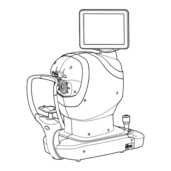
Page 17: Components
COMPONENTS COMPONENT NAMES Main body unit Measuring head Control panel Stylus pen holder Printer cover open button Printer cover MEASUREMENT switch Control lever Intraocular pressure measuring window Chinrest unit Measuring window Forehead rest * (for REF/KRT) Eye height mark Power supply unit Chinrest tissue pin POWER switch Chinrest *... -
Page 18: Operation Method Of Control Panel
OPERATION METHOD OF CONTROL PANEL The control panel is designed as a touch panel for performing various operations and settings. It displays images and shows information, including set conditions and measurement results. • Operate the control panel by your fingers or the accessory stylus pen. Do not use any sharp tool such as a ball point pen. - Page 19 Physician ID input button ..Displays the software keyboard. Enter the ID, name, etc. Displayed when “Physician ID” and “Use Physician ID” are set to ON on the Setup screen. R/L button........Selects the right/left eye. By tapping the button, the main body moves to the selected direction.
-
Page 20: Monitor Screen
Fog button ........Changes setting temporarily to perform fogging only in the first measurement or each time in the continuous measure- ment. All data button ........Displays all measurement data on the screen. Print out button ......Prints measurement results. Tap the button when no mea- surement data is present to feed the paper. -
Page 21: Control Panel Components (In Tono/Pachy Measurement Mode)
CONTROL PANEL COMPONENTS (IN TONO/PACHY MEASUREMENT MODE) MEASUREMENT SCREEN AUTO MODE MODE button Mode display/Mode switching Patient ID input button Physician ID input button Display R button L button Setting menu button Air check button T/P measurement mode Auto/Manual button selection button End button Start button... - Page 22 R button/L button.....Selects the right/left eye. By tapping the button, the main body unit moves to the selected direction. The selected but- ton is framed in purple. The layout where the R/L button is displayed reverses according to the position of the control panel.
-
Page 23: Monitor Screen
Meas. Count change button ...Switches the measurement count between one-time mea- surement and preset measurement count. -Preset measurement count (Runs the preset number of measurements) -One-time measurement (This is the factory default setting) All data button ........Displays all measurement data on the screen. Print out button ......Displayed when the instrument is in measurement standby. -
Page 24: Printer Output (In Ref/Krt Measurement Mode)
Refractive power measurement result (L) 43.50 7.77 43.25 7.80 43.25 7.79 -0.25 TOPCON logo mark Refractive power measurement result (R) TOPCON • C mark appears when the button is selected by manual Cataract operation. Adding the C mark occurs only for REF measurement values. - Page 25 R1-R2 7.80 7.77 43.25 7.79 R1-R2 -0.25 TOPCON • C mark appears when the button is selected by manual Cataract operation. Adding the C mark occurs only for REF measurement values. NOTE • The ( ) mark is attached when the measurement cannot be performed normally due to cataract, eyelids, eyelashes, blinking, etc.
-
Page 26: Printout Format Setting
FUNCTIONS ON SETUP SCREEN” on page 99. PRESET ITEM INITIAL Classic Barcode Operator ID Name Date Patient No/Patient ID Device ID number Common Serial number TOPCON logo Message Message data NULL NULL NULL NULL Line space Auto Cut Print order DATA DATA DATA... -
Page 27: Printer Output (In Tono/Pachy Measurement Mode)
Title of IOP ADJ Formula IOP ADJ FORMULA Adjustment Coefficient A : 520 B : 120 Topcon Logo mark TOPCON Message column Hello World As for the patient No., the result of the printing will differ depending on whether the patient ID is inputted or not inputted. - Page 28 Title of IOP ADJ Formula IOP ADJ FORMULA Center CCT Base/Adjustment Coefficient A : 520 B : 120 Topcon Logo mark TOPCON Message column Hello World • The “M” mark is printed on the value measured by manual measurement or measured by start button in Auto mode. (In the error of ERR, OVER, etc., NOTE the “M”...
- Page 29 IOP ADJ FORMULA Center CCT Base/ A : 520 B : 120 Adjustment Coefficient Topcon Logo mark TOPCON Message column Hello World • The “M” mark is printed on the value measured by manual measurement or measured by start button in Auto mode. (In the error of ERR, OVER, etc., NOTE the “M”...
-
Page 30: Preparations
PREPARATIONS • If the packaged box is damaged, please consult your authorized dealer or the offices listed on the back cover. • If the packaged box has been opened, please consult your authorized NOTE dealer or the offices listed on the back cover. •... - Page 31 After removing the joint, pull up the outer carton only. Remove the upper and lower bands fixing the inner packing material. Fixing band (upper) Fixing band (lower) Open the protective cushion to the right and left, then take off the vinyl sheet. Protective cushion Vinyl sheet PREPARATIONS...
-
Page 32: Installation
INSTALLATION • When moving the instrument, two people should lift from the bot- tom of the device. One person lifting the device may cause harm to his back or injury by falling parts. • When holding the bottom of the instrument, avoid touching a pro- jection of screws to prevent injury. -
Page 33: Connecting Power Cord
Remove the measuring window caps. Measuring window cap CONNECTING POWER CORD Be sure to connect the power plug to an AC 3-pin receptacle equipped WARNING with grounding. Connection with receptacle without grounding may cause fire and electric shock in case of short-circuiting. •... -
Page 34: Connecting External I/O Terminals
CONNECTING EXTERNAL I/O TERMINALS To avoid injury from electric shocks, do not connect anything other WARNING than the specified external equipment to the external I/O terminals. • To avoid electric shocks, do not touch the external connection terminal and the patient at the same time. •... -
Page 35: Data Input
USB bus power NOTE • Please connect USB devices while the POWER switch of this instrument is OFF. It may not correctly recognize USB devices if this instrument is in operation. • For questions about connections, contact your TOPCON dealer. PREPARATIONS... -
Page 36: Printer Paper Setting
• Be sure to use the specified printer paper. If you use the paper other than the specified, the printer may be broken or the instrument may not be able to use. • For printing paper, use the following paper specified by TOPCON. Item name Product code... -
Page 37: Supplying The Chinrest Tissue
Insert the printer paper in the direction shown below and pull out the paper end to your side by 7 to 8cm. Roll direction Bring the paper into the center, then close the printer cover. NOTE In case the printer cover is not firmly closed, printing will not start. SUPPLYING THE CHINREST TISSUE Set the chinrest tissue by chinrest tissue pins. -
Page 38: Region Selection Of The Initial Startup
REGION SELECTION OF THE INITIAL STARTUP Please select a region in the initial startup of this instrument. • This operation is done only at initial startup. • For an area besides Canada/Latin America, China, Europe, Germany and Japan, please choose the “General”. •... -
Page 39: Restore Default Settings
RESTORE DEFAULT SETTINGS If resetting the region to be used is required such as by setting the wrong region, perform the follow- ing operation. NOTE If the factory default is carried out, clear the setting information of all users. Tap the button Setting menu Setup screen is displayed. -
Page 40: Adjusting The Control Panel Position
ADJUSTING THE CONTROL PANEL POSITION Tapping the control panel controls operations including chinrest up-and-down movements, align- ment and measurement. It is possible to change the control panel position in the up-and-down and right-and-left directions. Adjust the control panel position optionally. •... -
Page 41: Basic Operations
BASIC OPERATIONS OPERATION FLOW CHART MEASURING PROCEDURE IN REF/KRT TONO/PACHY CONTINUOUS MEASUREMENT PREPARATION BEFORE MEASUREMENT Insert the power cord plug into the commercial power. TURNING ON THE INSTRUMENT (page 40) SELECTING THE MEASUREMENT MODE (page 43) CHECKING THE MEASURING NOZZLE (page 44) AIR CHECK (page 45) SETTING THE PATIENT ID (page 47) -
Page 42: Preparation Before Measurement
PREPARATION BEFORE MEASUREMENT • Do not put the patient's chin on the chinrest until the power is on. • If the POWER switch is turned ON immediately after turning OFF the NOTE POWER switch, it may be unable to restart by the protective function of power supply. -
Page 43: Brightness Adjustment Of Control Panel
The title screen and Measurement screen are displayed and the confirmation message of set- ting of safety stopper is displayed in a few seconds. Check the displayed contents and press button. • When pressing button, air automatically come out from the mea- NOTE surement nozzle and the check is performed. -
Page 44: Setting The Auto Contact Avoidance Function
SETTING THE AUTO CONTACT AVOIDANCE FUNCTION This instrument has an automatic contact avoidance function that detects when the measurement nozzle is too close to the patient during T/P measurement, then automatically stops the movement and retracts the measurement. This function is enabled at the factory. Shifts to the setting menu screen. -
Page 45: Selecting The Measurement Mode
SELECTING THE MEASUREMENT MODE This instrument has R/K measurement and T/P measurement, each of which has the following mea- surement modes. • R/K: REF/KRT measurement mode REF (Measurement of Spherical refractive power, Astigmatic refractive power and Direction of astigmatic axis), and KRT (Measurement of Cornea curvature radius, Direction of corneal principal meridian and Corneal refractive power) •... -
Page 46: Checking The Measuring Nozzle
CHECKING THE MEASURING NOZZLE Before TONO/PACHY measurement, a check of the measuring nozzle is required. Before measuring, check if there is any foreign matter on and CAUTION around the measuring nozzle. If there is any, it may enter and damage the patient's eye during the measurement. •... -
Page 47: Air Check
AIR CHECK Before TONO/PACHY measurement, an air check is required. This instrument is equipped with a function for checking correct operations of the measurement sys- tem inside the instrument. On the measurement standby screen of Auto mode in T/P mode, tap the button. - Page 48 If there is no object, a failure is suspected. Turn the POWER switch to OFF, unplug the power cord, and call your dealer or TOPCON at the address printed on the back cover of this manual.
-
Page 49: Setting The Patient Id
SETTING THE PATIENT ID Tap the button on the control panel. Patient ID input Tap the button and the patient ID input screen will pop up. Press the Patient ID input window and enter the Patient ID using the input buttons. Press the button after entering the ID to complete the entry. -
Page 50: Setting The Physician Id
SETTING THE PHYSICIAN ID Tap the button on the control panel. Physician ID input Tap the button and the physician ID input screen will pop up. Press the Physician ID input window and enter the Physician ID using the input buttons. Press button after entering the ID to complete the entry. -
Page 51: Setting The Patient Id (Using Mwl)
SETTING THE PATIENT ID (USING MWL) DICOM settings Make the necessary settings in advance. See “LIST OF SETUP ITEMS” for details on various settings. (see page 103) Enable MWL usage Patient ID Enter Press the button on the control panel. Enter the necessary search conditions and press the QUERY button. - Page 52 The search results screen appears. Select the required patient ID and press the button. OK Button Go back to the measurement screen and make sure the patient ID is updated. Patient ID BASIC OPERATIONS...
-
Page 53: Patient Positioning
PATIENT POSITIONING • Each time one patient is changed to another, replace the chinrest tissue with a new one. • To avoid electric shocks, do not touch the external connection terminal and the patient at the same time. CAUTION • When operating the chinrest up/down button, be careful not to pinch the patient's hand. - Page 54 Adjust the adjustable instrument table or the chair height for the patient to put his/her chin on the chinrest comfortably. Place the patient's chin on the chinrest and check that his/her forehead is touching to the fore- head rest. Press the button to adjust the chinrest height until the eye height mark of the UP/DOWN chinrest reaches the same height as the patient's eye.
-
Page 55: Setting The Safety Stopper
SETTING THE SAFETY STOPPER • Before measuring, set the safety stopper to prevent the intraocu- lar pressure measuring window from hitting the patient's eye. Set it respectively for the right and left eyes. • Set the safety stop from the side of the instrument. CAUTION Setting operations from other positions, it is not easy to check positions of the eye and intraocular pressure measuring window,... - Page 56 When the button is tapped, the Safety Stopper screen is called up. Safety Stopper Z-axis position Safety stopper position Safety stopper icon Z-axis position icon APPLY button Z-axis operating range OK button CANCEL button Operating the control panel, set the center of the Measurement screen to the cornea center of the patient.
- Page 57 By tapping the button, adjust the position of the z-axis posi- Measuring head forward/backward tion icon for the right/left eyes. At this moment, confirm alternately the distance between the patient’s eye and the measuring nozzle and the safety stopper screen, and adjust the position of the z-axis position icon.
-
Page 58: Measurement In Ref/Krt Tono/Pachy Continuous Measurement Mode
MEASUREMENT IN REF/KRTTONO/PACHY CONTINUOUS MEASUREMENT MODE In this mode the measurement is performed continuously left and right eye in REF/KRT and TONO/ PACHY. Before shipment the default setting is following order; right eye in REF/KRT, left eye in REF/KRT, left eye in TONO/PACHY and right eye in TONO/PACHY. -
Page 59: Setting The Auto Mode In Ref/Krt
SETTING THE AUTO MODE IN REF/KRT Check the Measurement screen. If the button is “AUTO”, the mode is Auto Auto/Manual mode. If “MANUAL” (Manual mode) is displayed, tap it and change to the Auto mode. ALIGNMENT AND MEASUREMENT IN REF/KRT Alignment can be operated from the control panel. - Page 60 • If the pupil is not displayed on the control panel, move the measuring head by press the control panel, checking the eye height mark on the measure- ment window as a guide (See page 51). • When the measuring head has reached the limit of movement (vertical/lat- eral directions), a yellow-colored limit mark appears on the control panel corner, showing it is the movement limit in that direction.
- Page 61 Alignment starts automatically, and measurement is performed. Move the measuring head to the other eye measurement position automatically and measurement is performed. The mea- surement results are displayed. • When the “Full Auto” of “R/L mode” is selected in the “Function(R/K)1” on the Setup screen, the instrument measuring head moves automatically to the other eye side for measuring.
-
Page 62: Setting The Auto Mode In Tono/Pachy
SETTING THE AUTO MODE IN TONO/PACHY Check the Measurement screen. If the button is “AUTO”, the mode is Auto Auto/Manual mode. If “MANUAL” (Manual mode) is displayed, tap it and change to the Auto mode. • When “IOP adjustment” is enabled, the corrected intraocular pressure value using the central corneal thickness base value and the adjustment coefficient is displayed on the Tono measurement data screen (when TONO and PACHY are measured). -
Page 63: Setting The Measuring Range
SETTING THE MEASURING RANGE In this instrument, the measuring range can be switched in 2 steps between “7-30” and “30-60”. Normally, “7-30” is used, but if the patient's intraocular pressure is high, switch it to “30-60”. The default setting is “7-30” upon power on. Check the Measurement screen. -
Page 64: Alignment And Measurement In Tono/Pachy
ALIGNMENT AND MEASUREMENT IN TONO/PACHY When the pupil is displayed, tap the display around the pupil. The measuring head moves to display the pupil image and alignment dot on the center of the screen. • If the pupil is not displayed on the control panel, move the measuring head by press the control panel, checking the eye height mark on the measure- ment window as a guide (See page 51). - Page 65 Alignment starts automatically. While moving the main body toward the patient, the focus of Measurement screen is changed, then measurement is performed. The measuring head moves automatically to the other eye side and measurement is per- formed. The measurement results are displayed. •...
-
Page 66: Displaying Measurement Values
DISPLAYING MEASUREMENT VALUES With regard to measurement values, for REF, KRT, TONO and PACHY, data of the latest measure- ment (only for TONO/PACHY, latest 3 measurements) are displayed on the control panel. numerical value only: Measurement was done correctly. numerical value with [ ]: When the reliability of measurement is low. (only TONO) ERROR: Measurement was not done correctly. -
Page 67: Print-Out Of Measurement Values
PRINT-OUT OF MEASUREMENT VALUES • To avoid a paper jam in the printer, do not feed the paper if it is partly cut or wrinkled. • To avoid discoloring of the printer paper (particularly the recording area) during storage, use a polypropylene bag and not one containing plasti- NOTE cizer (PVC, etc.). -
Page 68: Clearing Measurement Values
CLEARING MEASUREMENT VALUES Tap the button on the control panel. All clear All measurement values of both eyes are cleared. After clearing the measurement values, the measuring head moves to the NOTE “Meas. Start: Standby Pos.” position selected in the “Function(Common)1” on the Setup screen. -
Page 69: Displaying All Measurement Data
DISPLAYING ALL MEASUREMENT DATA It is possible to confirm all measurement data. Tap the button. All data The Data Display screen is displayed. Use the button to select the measurement data you want to REF / KRT / TONO / PACHY switching display. -
Page 70: Ref Measurement Data
REF MEASUREMENT DATA Right eye REF / KRT / TONO / PACHY switching button Left eye Measurement count Measurement item Measurement result values Exit button Measurement average values C mark appears when the mode is changed to the cataract mode manually during a measurement. -
Page 71: Krt Measurement Data
KRT MEASUREMENT DATA Right eye REF / KRT / TONO / PACHY switching button Left eye Measurement count Measurement item Measurement result values Exit button Measurement average values BASIC OPERATIONS... -
Page 72: Tono Measurement Data
TONO MEASUREMENT DATA • The display unit is varied according to the Settings of setup. Setup item: TONO display unit in intraocular pressure measurement “mmHg” in TONO measurement mode Right eye REF / KRT / TONO / PACHY switching button Left eye Measurement count Measurement item... -
Page 73: Pachy Measurement Data
PACHY MEASUREMENT DATA • The display unit is varied according to the Settings of setup. Right eye REF / KRT / TONO / PACHY switching button Left eye Measurement count Measurement item Measurement result values Exit button Measurement average values BASIC OPERATIONS... -
Page 74: Operation After Use
OPERATION AFTER USE Tap the button on control panel. A confirmation message for the end operation is displayed. Tap the button. Return the chinrest and measuring head to their last positions. The message of “End of operation in progress. Please wait until complete.” is displayed. The operation is complete, then the message of “End of operation complete. -
Page 75: Optional Operations
OPTIONAL OPERATIONS DISPLAYING THE PATIENT ID (PATIENT No.) OR OPERATOR ID Up to 20 characters of “Patient ID” or “Operator ID” managed by hospitals can be registered and displayed on the control panel or printer output. If no patient ID is inputted, the patient No. of each patient is allocated automatically. When “Required Patient ID”... -
Page 76: Manual Mode In Ref/Krt
MANUAL MODE IN REF/KRT • Adjust the height of the instrument table so that the patient can sit com- fortably. Otherwise, correct measurement values may not be obtained. • If the instrument is moved before measurement values are displayed, it NOTE may cause incorrect measurement results. - Page 77 • If the pupil is not displayed on the control panel, move the measuring head by pressing the control panel, checking the eye height mark on the measurement window as a guide (See page 51). • When the measuring head has reached the limit of movement (vertical/lat- eral directions), a yellow-colored limit mark appears on the control panel corner, showing it is the movement limit in that direction.
- Page 78 When the main body unit is brought closer to the patient's eye, Z alignment bars appear on the control panel screen. Outer alignment mark Z alignment bars Do not allow the eyelash and eyelid to cover the outer alignment mark to NOTE ensure stable measurement.
-
Page 79: Displaying Measurement Values
When the alignment dot becomes smaller in size and “Ready to measure” is displayed, tap the button to start measurement. If “Touch Measure” is set to “ON”, the measurement Start starts only by tapping the screen. (See page 106) “Touch Measure” is ON “Touch Measure”... -
Page 80: Measurement Of Cornea Diameter (In Ref/Krt)
MEASUREMENT OF CORNEA DIAMETER (IN REF/KRT) Tap the button. Target image Tap the button. Cornea diameter measurement NOTE The last measured image can be checked on this screen. The Cornea Diameter Measurement screen is displayed. Positioning bar Positioning bar Exit button R/L balance display Positioning bar control button (L) Positioning bar control button (R) - Page 81 If it has been measured, a still image is displayed, and if it has not been measured, “No Image” is displayed. Press the button to see the Live image. When the pupil is displayed, tap Live near the pupil. The measuring head moves to the position the pupil image and alignment dot are at the center of the screen.
- Page 82 Use the right button to move the right positioning bar to the right end of Positioning bar control the iris as seen from the control panel side. It is possible to move the positioning bar by tapping the positioning bar R/L NOTE balance display.
-
Page 83: Manual Mode In Tono/Pachy
MANUAL MODE IN TONO/PACHY Be careful not to get the finger or hand of the operator who is CAUTION opening the eyelids caught in the device. • Adjust the height of the instrument table so that the patient can sit com- fortably. -
Page 84: Alignment And Measurement
ALIGNMENT AND MEASUREMENT Alignment is operated on the control panel. Select the right/left eye by tapping the button/ button. When the pupil is displayed tap the pupil. The measuring head moves to the position the pupil image and alignment dot are at the center of the screen. •... - Page 85 When the measuring head is at the limit of movement in the forward direction, “Reaching set limit of stopper. Move measuring head.” is displayed, and when it is at the limit of movement in the backward direction, “FAR LIMIT” is displayed. If the position is detected, “TOO CLOSE” is displayed at a position closer than 3 mm to the patient's eye.
- Page 86 When the main body is brought closer to the patient's eye, Z alignment bars appear on the con- trol panel screen. Outer alignment mark Z alignment bars Do not allow the eyelash and eyelid to cover the outer alignment mark to NOTE ensure stable measurement.
-
Page 87: Displaying Measurement Values
Measurement starts by tapping the button. If “Touch Measure” is set to “ON”, the Start measurement starts only by tapping the screen. (See page 107) Touch Measure is ON Touch Measure is OFF • Even if fine alignment has not been achieved, measurement can be per- formed by tapping the button. -
Page 88: Iol Mode In Tono/Pachy
IOL MODE IN TONO/PACHY Alignment may not be performed normally with IOL inserted eye. If it occurs, NOTE carry out measurement in IOL mode. SETTING THE IOL MODE Check the Measurement screen. If is displayed, IOL mode is set. If no is displayed, tap the button to change to IOL mode. -
Page 89: One-Eye Measurement Mode
ONE-EYE MEASUREMENT MODE In auto mode, one eye measurement only can be measured. button or button side displayed in purple indicates the current measurement position. TO MEASURE ONLY THE LEFT EYE Tap the button to move the measuring head to the Left. When the moving is finished, tap the button again to display the lock icon on the... -
Page 90: To Measure Only The Right Eye
TO MEASURE ONLY THE RIGHT EYE The operation procedure is the same as when measuring only the left eye. When the lock icon is displayed (one-eye measurement mode), you can NOTE switch between the left and right eyes while keeping the locked state by tapping the button or button. -
Page 91: Operating The Control Lever
OPERATING THE CONTROL LEVER When switching the left and right eyes by the control lever, be sure to return the measuring head to the backward side by tilting the CAUTION control lever to the backward before moving the measuring head to the left or right. -
Page 92: Manual Mode In Ref/Krt
Measurement operation Measurement starts by pressing the MEASUREMENT switch at the top of the control lever. MANUAL MODE IN REF/KRT Set the “Change to M by lever” setting to ON to automatically switch to NOTE Manual model when the control lever is touched. Refer to “Change to M by lever”... -
Page 93: Alignment And Measurement
ALIGNMENT AND MEASUREMENT Select the right/left eye by tapping the button/ button or operating the control lever. Align the pupil display to the center of the screen. Use the control lever to align the center of the pupil within the alignment mark. At this time, tell the patient to look at red-roof house. - Page 94 If the instrument is too close to the patient's eye in comparison with the optimal alignment position, Z alignment red bars appear on the upper side of the center horizontal bar (light blue). If it is too far, Z alignment green bars appear on the lower side of the center horizontal bar (light blue). The number of bars are reduced accordingly as the optimal alignment reference position comes closer.
- Page 95 Measurement is performed and measurement values are displayed on the control panel. If you press and hold the MEASUREMENT switch of the control lever in the NOTE manual mode of REF/ KRT, perform the measurement once, over and over again. OPTIONAL OPERATIONS...
-
Page 96: Manual Mode In Tono/Pachy
MANUAL MODE IN TONO/PACHY Check the Measurement screen. If the button is “MANUAL”, the mode is Manual Auto/Manual mode. If “AUTO” (Auto mode) is displayed, tap it and change to “MANUAL”. SETTING THE MEASURING RANGE In this instrument, the measuring range can be switched in 2 steps between “7-30” and “30-60”. Normally, “7-30”... -
Page 97: Alignment And Measurement
ALIGNMENT AND MEASUREMENT Select the right/left eye by tapping the button/ button or operating the control lever. Use the control lever to align the center of the pupil within the alignment mark. At this time, tell the patient to look at the green alignment dot. While watching the anterior image, focus on the patient's eye by tilting control lever back and forth. - Page 98 The Z alignment bars appear when the alignment dot reaches within the alignment mark. Outer alignment mark Z alignment bars Do not allow the eyelash and eyelid to cover the outer alignment mark to NOTE ensure stable measurement. Otherwise, correct measurement values may not be obtained.
- Page 99 When the red or green Z alignment bars disappear and the alignment mark is turned green, the automatic measurement is performed or press the MEASUREMENT switch. * When “Auto Shoot” in “Function(Common)2” on the Setup screen is set to ON, operate the control lever to automatically start measurement once the alignment is complete.
-
Page 100: Adjusting The Height Of The Chinrest By Wide-Angle Anterior Observation Image
ADJUSTING THE HEIGHT OF THE CHINREST BY WIDE-ANGLE ANTERIOR OBSERVATION IMAGE If “Wide Angle” on the “Stand by screen” of the “Function(Common)2” of the setting screen is selected, it can adjust the chinrest position before measurement. The wide-angle anterior observation image screen is displayed when the power is turned on or when the button is pressed. -
Page 101: Setting Functions On Setup Screen
SETTING FUNCTIONS ON SETUP SCREEN OPERATING THE SETUP SCREEN Various functions can be set on the SETUP screen. PREPARATONS FOR SETTING Make sure that the power cord is connected. For connection, refer to “CONNECTING POWER CORD” on page 31. Turn ON the POWER switch. Tap the button on the control panel. -
Page 102: Outline Of Setup Screen Operations
OUTLINE OF SETUP SCREEN OPERATIONS Use the button and button to display the required page until the Next page Back page setting field you want to check or change is displayed in the Index Tap the and select the required setting field. Index Check the display of the setting descriptions for which you want to change the setting. -
Page 103: Pull-Down Menu
If the button appears in the Setting change operation part, tap button or ON/OFF button to change the setting. Instead of the button for the setting change operation part, the setting item may be ON/OFF selected from the pull-down menu. Alternatively, a numeric keypad for input (number key) and a keyboard may be displayed in a pop-up window. -
Page 104: Returning To The Measurement Screen
KEYBOARD: Tap the keyboard on the screen and enter characters. If there are several windows to enter, tap the window to enter the figure by keyboard. Tap the button to fix the entry. Enter window Tap the button to fix the setting change. NOTE The set value is updated when the button is pressed. -
Page 105: List Of Setup Items
LIST OF SETUP ITEMS The setup items consist of 30 indexes over 9 pages, divided by the items to be set up. System1 (Region: A=Canada / Latin America, C=China, E=Europe, D=Germany, J=Japan, G=General) Initial value (Region) Descriptions Options Details A C E D J G Buzzer (operation sound) does not sound. - Page 106 Network1 Initial value (Region) Descriptions Options Details A C E D J G LAN connection is off. LAN connection LAN connection is on. Does not output XML. XML file output Output XML. Upper and lowercase alphanumeric characters Shared Folder1 Set the shared folder 1 NULL “_”, “.”, “-”, “\”, space...
- Page 107 Function(Common)1 Initial value (Region) Descriptions Options Details A C E D J G Manual Default measurement mode is Manual. Meas. Start: A/M Select Auto Default measurement mode is Auto. Default measurement mode is RKTP R/KT/P continuous measurement. Meas. Start: Mode Select Default measurement mode is R/K measurement.
- Page 108 Function(R/K)1 Initial value (Region) Descriptions Options Details A C E D J G 1-10 Cont. Cycle The number of continuous measurements. Set by number display 0-99 When the measurement is error, Add Measure Set by number display. set the number of times of remeasurement. Every time Continuous fog is applied every time.
- Page 109 Function(T/P)1 Initial value (Region) Descriptions Options Details A C E D TONO is selected for the measurement mode at the start of T/P TONO measurement when “Meas. Start: Keep Prev. Mode” is INIT. Meas. Start: Measure Mode TONO/PACHY is selected for the measurement mode at the start of T/P measurement when “Meas.
- Page 110 Device ID number is printed. Serial No. is not printed. Serial number Serial No. is printed. TOPCON logo is not printed. TOPCON logo TOPCON logo is printed. Message is not printed. Message Message is printed.
- Page 111 Printer(R/K)1 Initial value (Region) Descriptions Options Details A C E D J G Print format of preset is All. Preset (All) Execution Refer to page 24 for details on the presetting. Print format of preset is Avg. Preset (Avg) Execution Refer to page 24 for details on the presetting.
- Page 112 Printer(REF) Initial value (Region) Descriptions Options Details A C E D J G VD (Vertex distance) value is not printed. VD (Vertex distance) value is printed. Cylinder sign is not printed. Cylinder sign Cylinder sign is printed. All the measurement value is printed. ...
- Page 113 Physician ID Initial value (Region) Descriptions Options Details A C E D J G Physician ID is not used. Use Physician ID Physician ID is used. Physician ID is not required. Physician ID request Physician ID is required. Physician ID is not fixed.
- Page 114 System Version Initial value (Region) Descriptions Options Details A C E D J G Main Application – Version of the main application is displayed. – – Version of the GUI application is displayed. – Export Initial value (Region) Descriptions Options Details A C E D J G Setting File is exported to the external USB device.
-
Page 115: Maintenance
MAINTENANCE To prevent damage and injury, do not install the instrument on an CAUTION uneven, unsteady or sloped surface. MAINTENANCE CHECKUPS Maintenance of this instrument includes maintenance items by the user and maintenance items by the manufacturer. USER MAINTENANCE ITEMS Item Inspection time Contents... -
Page 116: Inspection Of Measurement Accuracy
0.12D and measure. If the measurement result is significantly different from the value displayed NOTE on the model eye, call your dealer or TOPCON at the address printed on the back cover of this manual. MAINTENANCE AFTER USE • After using, refer to “HOW TO CLEAN THIS INSTRUMENT” on page 115. -
Page 117: How To Clean This Instrument
HOW TO CLEAN THIS INSTRUMENT CLEANING THE COMPONENTS THAT COME INTO CONTACT WITH THE PATIENT/OPERATOR • Clean with clean gauze soaked in rubbing alcohol before and after use and every time the patient/ operator changes. • If it is extremely dirty, dissolve the neutral detergent for tableware in lukewarm water, squeeze a cloth soaked in it, and wipe it. -
Page 118: Cleaning The Measuring Window
CLEANING THE MEASURING WINDOW Cleaning the REF/KRT measuring window • When dust or dirt adheres to the measuring window ... Blow off the dust or dirt with a blower. • When fingerprints or oil adheres to the measuring window... Blow off the dust and dirt with a blower and lightly wipe the surface with camera lens cleaner on a clean gauze. - Page 119 CLEANING THE MEASURING NOZZLE AND THE GLASS INSIDE THE MEASURING NOZZLE • If there is any foreign matter on or around the measuring nozzle, it may enter and damage the patient's eye during the measurement. If there is any, clean the measuring nozzle. •...
-
Page 120: Ordering Consumable Items
ORDERING CONSUMABLE ITEMS ORDERING CONSUMABLE ITEMS When ordering consumable items, tell the product name, product code and quantity to your dealer or TOPCON at the address listed on the back cover. Product name Product code Product name Product code Chinrest tissue... -
Page 121: Device Log Information
DEVICE LOG INFORMATION Logs can be exported to a maintenance USB flash drive designated by Topcon. Shifts to the setting menu screen. Tap the [Export] button of “System Log” listed in “Export” on page 9/9. MAINTENANCE... -
Page 122: Troubleshooting
TROUBLESHOOTING MESSAGE LIST Initializing. Please wait... Displayed when the main unit is being initialized at startup. Printer device might not be under An error has occurred with the built-in printer. normal operations after initializa- The printer may not be working properly, but you can continue to use it. tion. - Page 123 Start measurement by tapping Displayed when “Full Auto” measurement is possible. Tap the pupil to start pupil on screen. measurement automatically. Ready to measure. Displayed when measurement can be performed in Manual mode. Tap measurement position to Displayed as instruction of the measurement procedure in manual mode. Tap measure after manual focus.
- Page 124 Start alignment by tapping pupil Displayed on the Capture screen for corneal diameter measurement. Tap the on screen. pupil on the screen if you need alignment. Change of measurement head Displayed while switching the measurement target eye of the measuring head. position in progress (R/L).
- Page 125 Output data settings not set. Displayed when all output settings are OFF. Confirm that the output setting is Confirm settings. in the correct way. Printer failure. Displayed when the printer unit does not move normally, such as when the cut- Turn off/on unit and try again.
- Page 126 Duplicate IP address detected. Displayed when the IP address is duplicated. Confirm that the IP address set- Confirm in settings. ting of main instrument is in the correct way. (E14102) Cannot access network shared The network connection cannot be confirmed. Check the LAN cable connec- folder.
- Page 127 Error occurred during network Displayed when any of the shared folder settings fail. setup. Errors that occurred for each folder are displayed. Please check the network Check settings or connections. settings and connection. For details of the errors, check the description of each error. Shared Folder1 : Shared Folder2 : Shared Folder3 :...
- Page 128 Patient ID isn't selected. Displayed when a patient is not selected on the search result screen. Select a Select Patient ID in query result. patient for measurement and press the OK button. Success intercommunication Displayed upon successful intercommunication check with the server. check with MWL server.
-
Page 129: Air Check
If a problem is suspected, use the following check list. If following the instructions does not improve the condition, or if your problem is not included in the list, contact your dealer or TOPCON at the address on the back cover. CHECK LIST... -
Page 130: Printer Paper Jam
PRINTER PAPER JAM • To avoid injury to the operator, do not open or close the printer cover while the built-in printer is operating. • To avoid potential injury in case of malfunction, including a paper CAUTION jam, be sure to shut off the power before attempting to repair it. •... -
Page 131: Specifications And Performance
SPECIFICATIONS AND PERFORMANCE REF measurement Measuring range Spherical refractive power: ‒25 D to +22 D (Display value resolution: 0.12 D or 0.25 D) Astigmatic refractive power: 0D to ±10 D (Display value resolution: 0.12 D or 0.25 D) Direction of astigmatic axis: 0° to 180° (Display value resolution: 1° or 5°) (where, spherical refractive power + astigmatic refractive power ≤... -
Page 132: General Information On Usage And Maintenance
(4) Do not store the instrument where chemicals are stored or gas is generated. 3. Normal life span of the instrument: 8 years from delivery providing regular maintenance is performed [TOPCON data] Follow the respective handling methods for the transportation and storage conditions of external I/O devices. -
Page 133: Electric Rating
ELECTRIC RATING Source voltage: AC 100 V–240 V Frequency: 50–60 Hz Power input: 80 VA DIMENSIONS AND WEIGHT Dimensions: 332–422 mm (W) × 569–658 mm (D) × 504–760 mm (H) Weight: 23.2 kg SYSTEM CLASSIFICATION • Types of protection against electric shock: This instrument is classified as Class I equipment. -
Page 134: Operation Principle
OPERATION PRINCIPLE Refractometry: The light source (SLD) for refraction measurement incorporated in the measuring head emits luminous flux for refraction measurement and project it onto the retina. The camera incorporated in the measur- ing head receives the reflected image from the retina. The instrument software installed in the measur- ing head performs arithmetic processing of the reflected image and calculates the spherical refractive power, the astigmatic refractive power and the direction of astigmatic axis necessary for the correction lens to correct the vision of the subject eye to normal vision. -
Page 135: Disposal
This Product Contains a coin cell. You cannot replace batteries by yourself. When you need to replace and/or dispose bat- teries, contact your dealer or TOPCON listed on the back cover. EU Battery Directive NOTE This symbol is applicable for EU members states only. -
Page 136: Patient Environment
PATIENT ENVIRONMENT When the patient or inspector comes into contact with the devices (including the connecting devices) or when the patient or inspector is in contact with the person that touches the devices (including the con- necting devices), the patient environment is shown below. In the patient environment, use devices conforming to IEC 60601-1. -
Page 137: Requirements For The External Device
TLS1.2 or other encryp- tion for SQL server TCP/IP communication. The TRK-3 OMNIA can be connected to an IT network such as a personal computer or refractor (brand name “COMPU VISION CV-5000”) to output measurement results and patient information by operating the main unit. -
Page 138: Input/Output Interface Specifications
Device to be connected - NAS, Database Local area network Measurement result (output format: .xml) (LAN)* * TRK-3 OMNIA can connect directly to the IT network. Shared folder (USB) TRK-3 OMNIA Barcode reader Connection specifications - Wired LAN connection: 1000Base-T... -
Page 139: Electromagnetic Compatibility
Guidance and manufacturer's declaration - electromagnetic emissions The TRK-3 OMNIA is intended for use in the electromagnetic environment specified below. The customer or the user of the TRK-3 OMNIA should assure that it is used in such an environment. Emissions test... - Page 140 Guidance and manufacturer's declaration - electromagnetic immunity The TRK-3 OMNIA is intended for use in the electromagnetic environment specified below. The customer or the user of the TRK-3 OMNIA should assure that it is used in such an environment. Immunity test...
- Page 141 Guidance and manufacturer's declaration - electromagnetic immunity The TRK-3 OMNIA is intended for use in the electromagnetic environment specified below. The customer or the user of the TRK-3 OMNIA should assure that it is used in such an environment. Immunity test...
-
Page 142: Safety Of Laser Products
SAFETY OF LASER PRODUCTS • Use of controls or adjustments or performance of procedures other than those specified herein may result in hazardous radia- CAUTION tion exposure. • Do not remove the enclosures. Laser high-power is radiated. Light source REF measurement Laser product class Class 3B Output power... -
Page 143: Reference Material
ABOUT THE BARCODE AND THE QR CODE OF THE BACK COVER The barcode and the QR code of the back cover indicates the parts management code of the manual. Manufacturer 75-1 Hasunuma-cho, Itabashi-ku, Tokyo, 174-8580 Japan. Phone: +81-(0)3-3558-2522/2506 Fax: +81-(0)3-3966-5106 www.topcon.co.jp Parts management code 12345678-01-A Printed in Japan 2405-100TH... -
Page 144: Trk-3 Omnia Software License Terms
Plc and its licenser posses the copyright and the intellectual property right of the “Qt” software installed in TRK-3 OMNIA. TOPCON CORPORATION grants to you the right to use this TRK-3 OMNIA Software under the terms and condi- tions outlined below. -
Page 145: Limited Warranty
6. LIMITED WARRANTY 6.1 In the event that a hidden material defect is found by USER, USER shall notify TOPCON in writing of such defect directly or through its subsidiary, affiliate, distributor or agent within ninety (90) days after USER has received the SOFTWARE. -
Page 146: Governing Law
Japan. 10. ENTIRE AGREEMENT These LICENSE TERMS constitute the entire agreement between USER and TOPCON with respect to the sub- ject matter hereof, and shall supersede and cancel any and all prior written or oral agreements, undertakings, negotiations, communications, commitments, representations, publications and advertisement, etc. - Page 147 Marked on the rating nameplate. • Period of use: Please inform us of the date of purchase. • Defective condition: Please provide us with as much detail as possible. AUTO KERATO-REFRACTO TONOMETER TRK-3 OMNIA USER MANUAL Revision 2.00 Date of issue 2024-5-30 Published by TOPCON CORPORATION 75-1 Hasunuma-cho, Itabashi-ku, Tokyo, 174-8580 Japan.
- Page 148 AUTO KERATO-REFRACTO TONOMETER TRK-3 OMNIA TOPCON EUROPE MEDICAL B.V. (EU Importer) (European Representative)(European Sole Sales Company) Essebaan 11 2908 LJ Capelle a/d IJssel THE NETHERLANDS Phone: +31-(0)10-4585077 FAX: +31-(0)10-4585045 E-mail: medical@topcon.eu https://topconhealthcare.eu About Us https://global.topcon.com/about/group/ Manufacturer 75-1 Hasunuma-cho, Itabashi-ku, Tokyo, 174-8580 Japan.
Need help?
Do you have a question about the TRK-3 OMNIA and is the answer not in the manual?
Questions and answers