
Subscribe to Our Youtube Channel
Related Manuals for Speck BADUJET Perla


Summary of Contents for Speck BADUJET Perla
- Page 1 Translation of original operation manual Perla Riva Stella Overhang counter swim unit WG23.130.050-P...
- Page 2 All rights reserved. Contents may not be distributed, duplicated, edited or transferred to third parties without the written permission of SPECK Pumpen Verkaufsgesellschaft GmbH. This document and all attached documents are not subject to update service! Subject to technical modifications!
-
Page 3: Table Of Contents
Table of contents Table of contents About this document ............... 7 Using this manual ..............7 Target group................7 Other applicable documents ............7 1.3.1 Symbols and means of representation ........7 Safety ....................9 Intended use ................9 2.1.1 Possible misuse .............. - Page 4 Table of contents Transport ................. 16 Lifting the overhang counter swim unit ........16 Storage ................... 17 Returns ................... 17 Installation ..................18 Installation site (Qualified specialist) ........18 5.1.1 Assembly site ..............18 5.1.2 Installation position .............. 18 5.1.3 Checklist ................
- Page 5 Table of contents Decommissioning ..............31 6.4.1 Suggestion for winter conditions .......... 31 Faults ....................32 7.1.1 Check the pump after the overload switch has tripped ..34 7.1.2 Spare parts lists ..............34 Maintenance ................... 35 Care Instructions ..............35 Warranty .................
- Page 6 Glossary Unit Pump built into the system. Pressure line Pipe connected to the pressure discharge. Pump Machine with motor. Suction line Pipe connected to the suction discharge. 6 EN 09|2018...
-
Page 7: About This Document
About this document About this document Using this manual This manual is a component of the pump/unit. The pump/unit was manufactured and tested according to the generally accepted rules of technology. However, if the pump/unit is used incorrectly, not serviced enough or tampered with, danger to life and limb or material damage could result. - Page 8 About this document NOTICE Notes to prevent material damage, for better understanding or to optimise the workflow. Important information and technical notes are specially marked to explain correct operation. Symbol Meaning Instructions for a one-step action. Directions for a multi-step action. ...
-
Page 9: Safety
Safety Safety Intended use For installation in all types of swimming pool as a talking point, for fitness training, as a wave or air bubble bath, for underwater massage, after medical consultation, for endless no-turn swimming. Observing the following information is vital for intended use: •... -
Page 10: Safety Regulations
Safety – The personnels' responsibilities, for example working on the product, electric equipment or hydraulic systems, are set based on their qualifications and the job description. – The personnel have read this manual and understand the necessary working steps. Safety regulations The operator of the system is responsible for the adherence to all relevant statutory regulations and guidelines. -
Page 11: Rotating Parts
Safety Only use hoisting and load-bearing equipment which is suitable and technically sound. Do not stand under suspended loads. 2.7.2 Rotating parts There is a risk of shearing and crushing due to exposed rotating parts. Only perform servicing when the pump/unit is not in operation. -
Page 12: Suction Danger
Safety 2.7.5 Suction danger The following dangers can result: – Sucking towards, sucking in or jamming of the body or body parts, clothing, jewellery – Knotting of the hair Maintain installation distance to the pool wall of ≤ 45 mm ... -
Page 13: Dry Running
Safety 2.9.2 Dry running If run dry, mechanical seals and synthetic parts can be destroyed within only a few seconds. Do not allow the pump to run dry. This also applies to checking the rotation direction. Purge air from pump and suction line prior to start-up. 2.9.3 Overheating The following factors can result in the pump overheating:... -
Page 14: Safe Use Of The Product
Safety 2.9.8 Safe use of the product Safe use of the product is no longer guaranteed in the following instances: If the pipework is not in proper condition. If the pump seizes. See point 2.8 on page 12. ... -
Page 15: Description
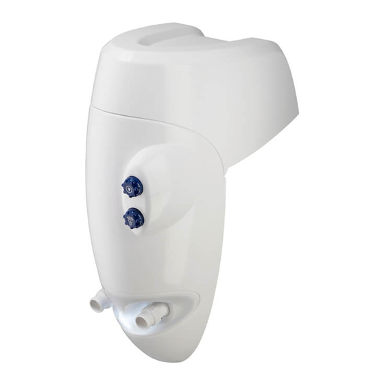
Description Description Components 54/1 WG23.130.051-P Fig. 2 Cover Light ON/OFF (2/1) Unit ON/OFF Cover (41) Light protection cover (54/1) Nozzle(s) Function The overhang counter swim unit draws water from the swimming pool via a suction line and pumps it back into the swimming pool via the pressure line through the nozzle(s). -
Page 16: Transport And Intermediate Storage
Transport and intermediate storage Transport and intermediate storage Transport Check the delivery conditions. – Check the packaging for transport damage. – Determine damages, document them with photographs and contact the distributor. Lifting the overhang counter swim unit DANGER Goods being transported can fall and result in death or crushing of limbs! The lifting hooks on the motor are only designed to hold weight of the motor. -
Page 17: Storage
Transport and intermediate storage Storage NOTICE Corrosion is possible due to storage in humid conditions with fluctuating temperatures! Condensation can corrode windings and metal parts. Store the pump/unit in a dry environment at a temperature which is as constant as possible. NOTICE Damage or loss of individual parts! ... -
Page 18: Installation
Installation Installation Installation site (Qualified specialist) 5.1.1 Assembly site Select the assembly site and prepare it in accordance with Fig. 4. If the unit is being used in an above ground pool, the telescopic support foot must be used, for attachment instructions See "Fig. -
Page 19: Securing The Unit
Installation 5.1.7 Securing the unit Set the unit on the metal vibration buffers and secure it with hexagonal bolts (32), toothed locked washers (31) and flat washers (30). See "Fig. 6". "Fig. 7" on page 21 5.1.8 Distance compensation Maintain the same overall distance between the housing and the pool edge. - Page 20 Installation Attaching the unit with the telescopic support foot WG23.130.063-P Fig. 5 Part Piece Description Article no. Elbow 231.9007.001 Telescopic support foot 231.9851.000 Hexagon bolt M12x35, Ks 586.9331.235 Lock Washer Ø13, A2 587.6797.120 Washer Ø13, A2 587.1251.200 Washer Ø8,4, A2 587.9021.080 Lock Washer Ø8,4, A2 578.6797.080...
- Page 21 Installation Fastening the unit to the ground WG23.130.061-P Fig. 6 WG23.130.062-P Fig. 7 Part Piece Description Article no. Dowel, M8, Brass 230.6006.006 Rubber metal buffer M8x36 230.6006.005 Washer Ø8,4, A2 587.9021.080 Lock washer Ø8,4, A2 587.6797.080 Hexagon bolt M8x25, A2 587.9330.825 09|2018 EN 21...
-
Page 22: Assembly Recommendation
Installation Assembly Recommendation Fig. 8 Electrical connection (Qualified specialist) WARNING Risk of electric shock due to incorrect connections! Electrical connections must always be carried out by authorised specialists. Observe VDE and utility company regulations. Install pumps for swimming pools and their protection according to DIN VDE 0100-702. -
Page 23: Connection By Customer
Installation Adjust minimum diameter of the electrical pipes to accommodate the motor output and pipe length. If hazardous situations can occur, provide an emergency off switch according to DIN EN 809. The builder/operator must make a decision according to this standard. 5.3.1 Connection by customer WARNING... -
Page 24: Wiring Diagram 3-Phase 400/230V 50 Hz
Installation 5.3.2 Wiring diagram 3-phase 400/230V 50 Hz Control box 3,15A 97 95 Pump 230V SELV Power: 230 V 1 N AC 50 Hz Connection by customer Pump Fusing at customer to DIN VDE 0100-702 Direction of rotation clockwise WG23.130.056-2-P Fig. -
Page 25: Commissioning/Decommissioning
Commissioning/Decommissioning Commissioning/Decommissioning Commissioning NOTICE The pump/unit can be damaged if it runs dry! Ensure that the pump/unit is always full of water. This also applies to checking the rotation direction. 6.1.1 Fill the overhang counter swim unit with water Remove the cover. -
Page 26: Checking How Easily The Pump Rotates
Commissioning/Decommissioning OPEN CLOSE WG23.130.065-2-P Fig. 12 Safety Switch When replacing the cover make sure the key snaps snugly into the safety switch. WG23.130.059-2-P Fig. 13 6.1.2 Checking how easily the pump rotates After longer idle periods, the pump must be checked for how easily it rotates while it is switched off. -
Page 27: Switch The Overhang Counter Swim Unit On
Commissioning/Decommissioning 6.1.3 Switch the overhang counter swim unit on Pre-requisites: • Unit must be filled with water • Cover must be on NOTICE The pump can be damaged if it runs dry! Purge air from the pump and suction line. Switch the pump/unit on. -
Page 28: Led Colour Variations
Commissioning/Decommissioning NOTICE The pump/unit may be damaged due to operation with a closed volume regulator. Only operate the pump/unit with an open volume regulator. 6.2.3 LED colour variations The LED colour variations can be changed by pressing the button (2) repeatedly within five seconds. -
Page 29: Do Not Stand On The Cover
Commissioning/Decommissioning 6.2.7 Do not stand on the cover NOTICE Damage to the cover. Do not stand on or load the cover. Do not use the cover as a starting block. 6.2.8 Optimal unit function NOTICE The unit may not function optimally if the water level is insufficient. ... -
Page 30: Using The Massage Hose
Commissioning/Decommissioning Fig. 15 Using the massage hose WARNING Injury due to incorrect use! Consult a doctor before using the massage hose on the affected body parts. No liability is accepted for misuse of the massage hose. Children may not use the massage hose! ... -
Page 31: Decommissioning
Commissioning/Decommissioning BADU Jet Stella Close the air regulation valve before the massage otherwise waer may leak out due to the increased pressure. Place a blind coupling exactly on one of the nozzles and latch it in. Put the coupling of the massage hose on the second nozzle and also latch it in. -
Page 32: Faults
Faults Faults NOTICE It is normal for a few drops of water to escape from the mechanical seal from time to time. This is especially true during the break-in period. Depending on the water quality and number of operating hours, the mechanical seal can begin to leak. - Page 33 Faults Problem: Pump seizes. Possible cause Solution Mechanical seal is stuck. Turn the motor shaft. See point 6.1.2 on page 26. Clean pump and pump parts. Problem: Pump leaks. Possible cause Solution Mechanical seal is worn or Have a professional replace the mechanical damaged.
-
Page 34: Check The Pump After The Overload Switch Has Tripped
Have an electrician test the power supply, fuses and power consumption. If the built-in or external overload switch switches the motor off again, notify Customer Services. 7.1.2 Spare parts lists Spare parts lists for each pump can be found on the website www.speck-pumps.com. 34 EN 09|2018... -
Page 35: Maintenance
Maintenance Maintenance NOTICE Before maintenance work, close all shut-off valves and drain all pipes. When? What? Regularly Check the pump is not leaking Check the stability of the unit, all impurities should be removed Check the electrical contacts in general Separate potential connector ... -
Page 36: Warranty
Failure to comply with the safety instructions may void the warranty. 8.2.1 Safety related spare parts – Safety switch (cover) – Guide wall – Telescopic support foot Service addresses Service addresses can be found on our website www.speck- pumps.com. 36 EN 09|2018... -
Page 37: Disposal
Disposal Disposal Collect harmful media and dispose of it according to the regulations. At the end of its service life, the pump/unit or individual components must be disposed of correctly. Disposal in the household waste is not permitted! ... -
Page 38: Technical Data
Technical data Technical data Technical data BADU Jet BADU Jet BADU Jet 50 Hz Perla Riva Stella Jet pump 21-81/32 G 21-81/31 RG 21-81/33 G 21-81/32 RG Pump flow rate 40/40 58/54 [m³/h] Voltage 3~/1~ [V] 400/230 / 400/230 / 400/230 Power input P 2.07/2.12... -
Page 39: 10.1 Dimensional Drawing
Technical data 10.1 Dimensional drawing BADU Jet Perla/BADU Jet Riva ≤45 mm ≤45 mm (EN 13451) (EN 13451) WG23.130.054-P Fig. 16 BADU Jet Stella ≤45 mm ≤45 mm (EN 13451) (EN 13451) WG23.130.055-P Fig. 17 09|2018 EN 39... -
Page 40: Index
Index Index Assembly Recommendation 22 Maintenance 35 Mechanical seal 32 Commissioning 25 Connection by customer 19, 23 Operation 27 Decommissioning 25, 31 Qualified specialist 18, 19, 22 Disposal 37 Securing the unit 19 Electrical connection 19, 22 Spare parts 10 Storage 17 Suggestion for winter conditions 31 Faults 12, 32...
Need help?
Do you have a question about the BADUJET Perla and is the answer not in the manual?
Questions and answers