Table of Contents
Advertisement
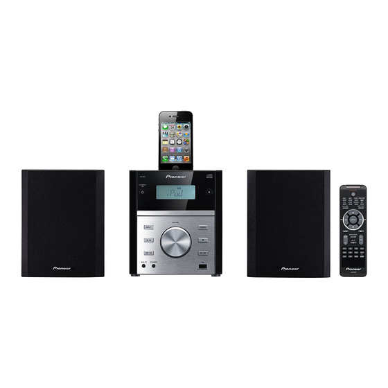
DVD Receiver System
X-EM21V
X-EM11V
THIS MANUAL IS APPLICABLE TO THE FOLLOWING MODEL(S) AND TYPE(S).
Model
Type
X-EM21V
YXE8
X-EM21V
LXE
X-EM21V
AXQ5
X-EM11V
AXQ5
PIONEER CORPORATION
PIONEER ELECTRONICS (USA) INC. P.O. Box 1760, Long Beach, CA 90801-1760, U.S.A.
PIONEER EUROPE NV Haven 1087, Keetberglaan 1, 9120 Melsele, Belgium
PIONEER ELECTRONICS ASIACENTRE PTE. LTD. 253 Alexandra Road, #04-01, Singapore 159936
PIONEER CORPORATION
Power Requirement
AC 220 V to 240 V
AC 220 V to 240 V
AC 220 V
AC 220 V
1-1, Shin-ogura, Saiwai-ku, Kawasaki-shi, Kanagawa 212-0031, Japan
2012
X-EM21V
Region
No.
2
3
5
5
K-MZV AUG.
ORDER NO.
RRV4374
Remarks
2012 Printed in Japan
Advertisement
Table of Contents

Related Manuals for Pioneer X-EM11V


Summary of Contents for Pioneer X-EM11V
- Page 1 PIONEER CORPORATION 1-1, Shin-ogura, Saiwai-ku, Kawasaki-shi, Kanagawa 212-0031, Japan PIONEER ELECTRONICS (USA) INC. P.O. Box 1760, Long Beach, CA 90801-1760, U.S.A. PIONEER EUROPE NV Haven 1087, Keetberglaan 1, 9120 Melsele, Belgium PIONEER ELECTRONICS ASIACENTRE PTE. LTD. 253 Alexandra Road, #04-01, Singapore 159936...
-
Page 2: Safety Information
SAFETY INFORMATION This service manual is intended for qualified service technicians; it is not meant for the casual do-it- yourselfer. Qualified technicians have the necessary test equipment and tools, and have been trained to properly and safely repair complex products such as those covered by this manual. Improperly performed repairs can adversely affect the safety and reliability of the product and may void the warranty. -
Page 3: Table Of Contents
CONTENTS SAFETY INFORMATION................................2 1. SERVICE PRECAUTIONS ..............................4 1.1 NOTES ON SOLDERING ............................... 4 1.2 NOTES ON REPLACING THE MECHA ASSY....................... 4 2. SPECIFICATIONS................................. 5 3. BASIC ITEMS FOR SERVICE .............................. 6 3.1 CHECK POINTS AFTER SERVICING ........................... 6 3.2 JIGS LIST .................................. -
Page 4: Service Precautions
1. SERVICE PRECAUTIONS 1.1 NOTES ON SOLDERING • For environmental protection, lead-free solder is used on the printed circuit boards mounted in this unit. Be sure to use lead-free solder and a soldering iron that can meet specifications for use with lead-free solders for repairs accompanied by reworking of soldering. -
Page 5: Specifications
• General information AC power.... 220 V to 240 V, 50 Hz/60 Hz (YXE8, LXE) 220 V, 50 Hz (AXQ5) Operation power consumption....28 W(X-EM21V) 18 W(X-EM11V) Standby power consumption ........≤ 0.6 W USB Direct........USB 1.1/2.0 (Full Speed) Dimensions –... -
Page 6: Basic Items For Service
3. BASIC ITEMS FOR SERVICE 3.1 CHECK POINTS AFTER SERVICING Items to be checked after servicing To keep the product quality after servicing, confirm recommended check points shown below. Procedure Check points Confirm whether the customer complain has been solved. The customer complain must not be reappeared. -
Page 7: Pcb Locations
3.3 PCB LOCATIONS Note: This photo is X-EM21V. The iPod dock is not equipped with in X-EM11V. • Rear view iPOD ASSY (X-EM21V only) DISPLAY LCD SMPS ASSY ASSY VOL ASSY AUX ASSY MAIN ASSY USB ASSY MECHA ASSY NOTES: Parts marked by “NSP”... -
Page 8: Block Diagram
4. BLOCK DIAGRAM 4.1 OVERALL WIRING DIAGRAM 1/8- VOL ASSY (X-EM21V: X-EM21V-04800-00) MAIN ASSY (X-EM11V: X-EM11V-04800-00) (X-EM21V/YXE8: X-EM21V-02800-00- (X-EM21V/LXE: X-EM21V-02800-00-A (X-EM21V/AXQ5: X-EM21V-02800-00 (X-EM11V/AXQ5: X-EM11V-02800-00 DISPLAY LCD ASSY (X-EM21V: X-EM21V-03800-00) 1.KEY (X-EM11V: X-EM11V-03800-00) 2.VOL- 235-110080-210 3.VLO+ 4.IR 5.LCD+5V 11/80 6.CD-VDD 7.GND *1.00mm... - Page 9 MECHA ASSY (EM2-100002-356) CN701 1.M+ V-02800-00-E) 2.M- 3.OP-SW -02800-00-A) 4.GND 5.CL-SW V-02800-00-C) V-02800-00-C) XP902 1.SL+ 2.SL- 3.LIMIT 4.GND 5.SP+ 1.F+ 6.SP- 2.F- 3.T+ 4.T- 7.LDSW 8.RFO CN902 10.B 11.F 12.RFGND 13.VREF_OPU *0.50mm 14.A+5V 15.E 16.RFGND 17.VR_CD 18.VR_DVD 19.PUH_CDLD 20.MDI 21.A+5V 22.RFGND 23.PUH_DVDLD 24.RFGND...
-
Page 10: Overall Block Diagram
4.2 OVERALL BLOCK DIAGRAM MAIN ASSY AUX ASSY IC503 IC504 iPOD ASSY IC602 (X-EM21V only) IC101 IC703 IC701 DISPLAY LCD IC801 LCD801 ASSY IC704 U901 IC702 U903 MECHA ASSY U904 U905 X-EM21V... - Page 11 AUX ASSY IC504 IC501 IC601 X-EM21V only IC302 U907 IC703 U906 IC704 U901 SMPS ASSY U905 X-EM21V...
-
Page 12: Diagnosis
5. DIAGNOSIS 5.1 TROUBLESHOOTING [1] Operations with a DVD or CD not possible 1. Focus RF system check 2. Tracking system check 3. Spindle motor system check 4. Miscellaneous 1. Focus RF system check After a DVD or CD is placed, the tray can be closed, but "NO DISC" is displayed. 1. - Page 13 3. Spindle motor system check Does the unit try to start playing when the OPEN/CLOSE button is pressed without a disc loaded? 1. Can the spindle motor turn a little? The circuit of the spindle-motor driver is normal. (See the waveforms in Fig. 4.) Check the peripheries of Pin 114 of U901 and 2.
- Page 14 [2] Operations with a USB memory device not possible "NO USB" is displayed. 1. Check power from U901 (SPHE8202RQ-D) and XP906. 2. Check the communication line between IC701 (CA6817) and U901 (SPHE8202RQ-D). [3] Data in a USB memory device cannot be played. Data in the USB memory device cannot be played even if the USB operation key is pressed.
- Page 15 [4] Operations with an iPod are not possible (only for the X-EM21V) The message "iPod" remains displayed on the LCD. 1. Check power from IC403 (IPOD+5V). 2. Check the iPod communication line between IC701 (CA6817) and CN601. Check of the iPod system Select the iPod function, by pressing the INPUT button on the main unit (iPod button on the remote control unit), then insert an iPod into the iPod dock to connect it with the DOCK connector.
- Page 16 [5] No power Check if the voltage at Pins 1 and 2 of CN1102 The SMPS Assy or the connection cable may be Is the Power indictor lit? on the SMPS Assy and of CN402 on the MAIN defective and require replacement. Assy is 13 V.
- Page 17 Has the protection circuit for TDA7491HV TDA7491HV (IC302) of the POWER amplifier is (IC302) of the POWER amplifier been activated defective. Replace the MAIN Assy. (is the signal level from Pin 28 high)? Has overvoltage protection been activated for Has undervoltage protection been activated for TDA7491HV (IC302) of the POWER amplifier ? TDA7491HV (IC302) of the POWER amplifier? (Is the voltage at Pins 6, 7, 12, and 13 20 V or...
- Page 18 [7] No picture (DVD) [COMPOSITE] To the flowchart "Operations with a DVD or CD Is sound output? not possible". U901 (SPHE8202RQ) is defective. Check the output from Pin 69 of U901. (Fig. 13) Replace the MAIN Assy. L909 or D910 or XP905 (VIDEO) is defective. Check the output from XP905 (VIDEO).
-
Page 19: How To Evaluate Ld Deterioration Of Pickup Assy
5.2 HOW TO EVALUATE LD DETERIORATION OF PICKUP ASSY If CD cannot be played, LD of pickup Assy may be deteriorated. • Carry out the evaluation in the following procedure, uisng CD disc equals to STD-905, YEDS-7. Evaluate the waveform of U901 pin 92 (refer to the photo) of MAIN Assy. →... -
Page 20: Protection Circuit
5.3 PROTECTION CIRCUIT [AMP IC periphery circuit] [STBY pin (Pin 20) periphery circuit] Pin 28 (DIAG): Error diagnosis output terminal [Protection operation] Over-voltage protection (OVP) If the supply voltage (IC302 pins 6,7,12,13) exceeds 20 V (nominal) the over-voltage protection is activated which forces the outputs (SP-OUT 2,3,8,9,10,11,16,17) to the high-impedance state. -
Page 21: Ic Information
5.4 IC INFORMATION (TDA7491HV)(MAIN ASSY: IC302) 20 W + 20 W dual BTL class-D audio amplifier • Block Diagram • Pin Function Name Type Description SUB_GND POWER Connect to the frame OUTPUTB Positive PWM for right channel PGNDB POWER Power stage round for right channel PVCCB POWER Power supply for right channel... -
Page 22: Disassembly
• Rear/Bottom view Bottom section • Rear view (6) Disconnect the antenna cable. Antenna cable (7) Disconnect the one connector. (CN402) CN402 MAIN Assy MAIN Assy Note: This photo is X-EM21V. The iPod dock is not equipped with in X-EM11V. X-EM21V... - Page 23 [2] Front Section (1) Unhook the two hooks. Front Note: This photo is X-EM21V. The iPod dock is not equipped with in X-EM11V. (2) Disconnect the one flexible cable. (CN601)(X-EM21 only) (3) Disconnect the one flexible cable and three connectors.
- Page 24 [3] Diagnosis (1) Reassemble the front section. Front section (2) Reassemble the bottom section. Bottom section (3) Connect the speaker cable connection jig. MAIN Assy Speaker cable connection jig (GGD1814) • Rear view [4] MAIN Assy and MECHA Assy (1) Disconnect the two connectors. Clamper section (CN701, XP902) (2) Remove the MAIN Assy by removing the four...
-
Page 25: Each Setting And Adjustment
8. EACH SETTING AND ADJUSTMENT 8.1 NECESSARY ITEMS TO BE NOTED After replacing the MAIN Assy, be sure to check the version of the firmware, and if it is not the latest one, update to the latest version. 8.2 SPECIAL KEY FUNCTION SPECIFICATIONS Function Model Operation... -
Page 26: Updating Of The Firmware (Dvd Microcomputer)
8.4 UPDATING OF THE FIRMWARE (DVD MICROCOMPUTER) Procedures 1 Decompress the supplied file (with the extension .RAR). The decompressed file will have the extension .BIN. 2 Copy the .BIN file mentioned in Step 1 to a USB memory device. 3 Connect a TV to the unit. 4 Press the INPUT button of the unit to set it to USB mode. - Page 27 X-EM21V...
-
Page 28: Exploded Views And Parts List
9. EXPLODED VIEWS AND PARTS LIST NOTES: Parts marked by “NSP” are generally unavailable because they are not in our Master Spare Parts List. The > mark found on some component parts indicates the importance of the safety factor of the part. Therefore, when replacing, be sure to use parts of identical designation. - Page 29 8 Poly Bag (Speaker) 710-250021-00 9 Cushion (One Pair) 874-EM1121-002 10 Gift Box See Contrast table (2) (2) CONTRAST TABLE X-EM21V/YXE8, LXE, AXQ5 and X-EM11V/AXQ5 are constructed the same except for the following: Mark Symbol and Description X-EM21V/YXE8 X-EM21V/LXE X-EM21V/AXQ5 X-EM11V/AXQ5...
-
Page 30: Exterior Section
9.2 EXTERIOR SECTION X-EM21V X-EM21V only only X-EM21V only Note: Apply silicon bond GYA1011 at replacing the antenna. Be careful to attach it too much. Bond (GYA1011) AXQ5 only X-EM21V... - Page 31 238-217040-203 19 Top Panel See Contrast table (2) 20 Front Panel Assy See Contrast table (2) (2) CONTRAST TABLE X-EM21V/YXE8, LXE, AXQ5 and X-EM11V/AXQ5 are constructed the same except for the following: Mark Symbol and Description X-EM21V/YXE8 X-EM21V/LXE X-EM21V/AXQ5 X-EM11V/AXQ5...
-
Page 32: Schematic Diagram
10. SCHEMATIC DIAGRAM 10.1 MAIN ASSY (1/8) X701 Q703 32.768KHZ IC703 S8550 24LC02 PWR-EN +3.3V XOUT R718 1 A0 +3.3V R779 2 A1 3 A2 4 GND R781 Q704 P-EN S8550 Q701 S8550 R721 RESET +3.3V +3.3V R771 100K R787 Region Setting 1 VSS_D RX1/GP5... - Page 33 2).COMPONENTS MARKED WITH HAVE CRITICAL PWR-EN CHARACTERISTICS. ONLY REPLACE WITH THE COMPONENT OF THE SAME TYPE NUMBER 3).SUBJECT TO CHANGE WITHOUT NOTICE DVD-EN OPEN CLOCK DATA DVD-RX DVD-TX ACC-POW ACC-DET MAIN ASSY (X-EM21V/YXE8: X-EM21V-02800-00-E) (X-EM21V/LXE: X-EM21V-02800-00-A) (X-EM21V/AXQ5: X-EM21V-02800-00-C) (X-EM11V/AXQ5: X-EM11V-02800-00-C) X-EM21V...
-
Page 34: Main Assy (2/8)
10.2 MAIN ASSY (2/8) FM COB PWB. FMANT ANT-FM IC101 Si4704/05 DOUT (TU) C109 C115 LOUT C114 RFGND ROUT D103 0.1U C102 C116 C117 0.01U 0.01U C101 R102 C105 C104 X101 C113 32.768KHZ FB300R L105 TU-RET C112 1000P CAUTION: 1).DISCONNECT POWER CORD BEFORE SERVING 2).COMPONENTS MARKED WITH HAVE CRITICAL CHARACTERISTICS. - Page 35 MAIN ASSY (X-EM21V/YXE8: X-EM21V-02800-00-E) (X-EM21V/LXE: X-EM21V-02800-00-A) (X-EM21V/AXQ5: X-EM21V-02800-00-C) (X-EM11V/AXQ5: X-EM11V-02800-00-C) 100uH L404 TU-VCC A+5V (TU) C115 L-CH C114 R-CH AVCC C116 C117 R101 0.01U 0.01U AVCC R123 FB300R 330R L101 (TU) TU-L C119 R124 100K (TU) Q103 L-CH S9014 L107...
-
Page 36: Main Assy (3/8)
10.3 MAIN ASSY (3/8) IC503 D2761 R502 A+8V CN501 C659 C660 CON-2.0-8P (AU) 3300pF 3300pF C657 AUX-L (AU) C658 2 OUTL OUTR A-LCH 2.2U R566 R565 R570 2.2U 8.2k 8.2k 180k AUX-R (AU) C574 C573 AUX-L AUX-DET R569 2.2U 2.2U R568 D508 180k... - Page 37 C570 C594 R622 R551 C585 R558 R539 HL-IN HL-IN HP-L C630 100R R616 220U6.3 AF-L 1U/OR Note:Component Value Format(X-EM21V/X-EM11V) 22.1K Example:R563 (5.6k/1.5k) C647 (iPod) R633 IPOD-L 2.2U MAIN ASSY (X-EM21V/YXE8: X-EM21V-02800-00-E) 22.1K (X-EM21V/LXE: X-EM21V-02800-00-A) (X-EM21V/AXQ5: X-EM21V-02800-00-C) C641 R638 IPOD-R (X-EM11V/AXQ5: X-EM11V-02800-00-C) 2.2U...
-
Page 38: Main Assy (4/8)
10.4 MAIN ASSY (4/8) L303 FB/AI 0.1U C340 36 VSS SUBGND 35 SVCC OUTPB C342 34 VREF OUTP_B 33 INNB PGNDB R329 2.2U R303 C319 C304 32 INPB PGND_B AF-L 4.7K R340 31 GAIN1 PVCCB R339 30 GAIN0 PVCC_B C341 29 SVR OUTNB IC302... - Page 39 MAIN ASSY (X-EM21V/YXE8: X-EM21V-02800-00-E) (X-EM21V/LXE: X-EM21V-02800-00-A) (X-EM21V/AXQ5: X-EM21V-02800-00-C) (X-EM11V/AXQ5: X-EM11V-02800-00-C) : AUDIO SIGNAL ROUTE (L ch) Speaker-L L303 +13V FB/AI JK301 C316 L307 0.22/M 8 OHM / 10W 33UH(A) L308 33UH(A) C323 L301 0.22/M 33UH(A) L302 8 OHM / 10W...
-
Page 40: Main Assy (5/8)
10.5 MAIN ASSY (5/8) Q410 B772 M+7V +13V A+8V R402 Q404 S8050 R428 A+5V 4.7R R412 R401 PWR-EN R438 820R Q402 S9014 4.7R R427 820R Q408 S8550 AU_12V +13V R433 R432 PWR-EN R419 Q409 PWR-EN S9014 33uH(A) L401 IPOD+5V IC401 ATD2502 U+5V Vout... - Page 41 MAIN ASSY (X-EM21V/YXE8: X-EM21V-02800-00-E) (X-EM21V/LXE: X-EM21V-02800-00-A) (X-EM21V/AXQ5: X-EM21V-02800-00-C) (X-EM11V/AXQ5: X-EM11V-02800-00-C) Q411 A8550 +13V R421 Q404 S8050 R412 R436 820R PWR-EN Q407 S9014 R427 820R C429 33uH(A) 8 SS 0.01U 7 EN +13V 6 COMP 5 FB IC403 TG1484 for X-EM21V +3.3V...
-
Page 42: Main Assy (6/8)
10.6 MAIN ASSY (6/8) DV33 Crystal R929 R929 4.7K 4.7K XP904 XP904 R930 R930 Y901 Y901 R931 R931 4pin/2.0mm 4pin/2.0mm EC954 EC954 10uF16V 10uF16V C914 C914 C913 C913 27MHz 27MHz 33pF 33pF 33pF 33pF C915 C915 C916 C916 C917 C917 R933 R933 Q911... - Page 43 MAIN ASSY (X-EM21V/YXE8: X-EM21V-02800-00-E) modify (X-EM21V/LXE: X-EM21V-02800-00-A) (X-EM21V/AXQ5: X-EM21V-02800-00-C) R928 R928 FV33 URST# (X-EM11V/AXQ5: X-EM11V-02800-00-C) R930 R930 TP901 TP901 EC954 EC954 10uF16V 10uF16V R932 R932 URST# B1-U1-U1 R933 R933 Q911 Q911 2N3904 2N3904 SOT-23 SOT-23 C919 C919 C1014 C1014 0.1uF 0.1uF...
-
Page 44: Main Assy (7/8)
10.7 MAIN ASSY (7/8) RF3.3V RFGND A+5V BC906 BC906 EC910 EC910 SPM- R922 R922 0.1uF 0.1uF 47uF/16V 47uF/16V U903 U903 VOTK+ RFGND Q909 Q909 VOTK- LDO_CD MO5V VOLD+ VOLD- LDSW 2SB1132(R/type) 2SB1132(R/type) VCC2 PUH_CDLD VCTL VREF_OPU BC908 0.1uF BC908 0.1uF RFGND BC909 0.1uF BC909... - Page 45 MAIN ASSY (X-EM21V/YXE8: X-EM21V-02800-00-E) (X-EM21V/LXE: X-EM21V-02800-00-A) (X-EM21V/AXQ5: X-EM21V-02800-00-C) (X-EM11V/AXQ5: X-EM11V-02800-00-C) MO5V SPM- SP-A U903 U903 VOTK+ VOFC+ Inor=155mA VOTK- VOFC- D902 D902 Istandby:8mA SPM+ VOLD+ VOSL- SPM- MO5V 1N4001 1N4001 VOLD- VOSL+ LOAD+ D903 1N4001 D903 1N4001 VCC2 VOTR+ LOAD-...
-
Page 46: Main Assy (8/8)
10.8 MAIN ASSY (8/8) 27K1% 27K1% R960 R960 C950 C950 120pF 120pF DVD_L DVD_R R961 R961 R962 R962 4.7K1% 4.7K1% (DVD) (DVD) R963 R963 (DVD) EC923 EC923 10uF16V 10uF16V C951 C951 0.1uF 0.1uF REFA U906A U906A C953 C953 LM4558 LM4558 R965 R965 R966... - Page 47 B/U_O G/Y_O RCA/VIDEO/OUT RCA/VIDEO/OUT C965 C965 C961 C961 C963 C963 C962 C962 100pF 100pF 100pF 100pF 100pF 100pF 100pF 100pF DVD_MUTE MAIN ASSY (X-EM21V/YXE8: X-EM21V-02800-00-E) (X-EM21V/LXE: X-EM21V-02800-00-A) (X-EM21V/AXQ5: X-EM21V-02800-00-C) C966 C966 C967 C967 (X-EM11V/AXQ5: X-EM11V-02800-00-C) 1000pF 1000pF 1000pF 1000pF X-EM21V...
-
Page 48: Ipod, Usb And Aux Assys
10.9 iPOD, USB and AUX ASSYS USB ASSY (X-EM21V: X-EM21V-06800-00) (X-EM11V: X-EM11V-06800-00) CN503 CON-2.0-4P JK501 USB-JACK USB-VCC FB 0805 L502 USB-VCC 2.2R R579 XP906 2.2R R578 U-GND FB 0805 L513 U-GND CN504 CON-2.0-2P CN403 iPOD ASSY (X-EM21V-07800-00)(X-EM21V ONLY) (iPod) : AUDIO SIGNAL ROUTE (iPod L ch) - Page 49 AUX ASSY (X-EM21V: X-EM21V-05800-00) : AUDIO SIGNAL ROUTE (L ch) (X-EM11V: X-EM11V-05800-00) (AU) : AUDIO SIGNAL ROUTE (AUX L ch) FB300R L523 C535 (AU) R512 FB300R L504 330R 2.2U C519 R529 JK503 L503 FB300R 330R 2.2U (AU) CN506 CON-2.0-8P (AU)
-
Page 50: Display Lcd And Vol Assys
10.10 DISPLAY LCD and VOL ASSYS DISPLAY LCD ASSY (X-EM21V: X-EM21V-03800-00) (X-EM11V: X-EM11V-03800-00) R805 8.2k SW808 P.BASS PROG. RANDOM REPEAT ALBUM DIVX DOLBY SLEEP DISC IPOD PAUSE PLAY TIMER P.BASS ROCK JAZZ CLASSIC MONO LCD801 Q804 S9014 R827 C807 SEG6... - Page 51 VOL ASSY (X-EM21V: X-EM21V-04800-00) (X-EM11V: X-EM11V-04800-00) R805 R804 R820 R819 R818 R817 AD-KEY 8.2k 3.3k 1.8k 1.2k 820R 680R SW808 SW807 SW806 SW805 SW804 SW803 P.BASS STOP SKP+ SKP- PLAY/PAUSE INPUT VOL801 CN804 ENCODER-VR CON-2.0-4P VOL- VOL- VOL+ VOL+ AD-KEY...
-
Page 52: Smps Assy
10.11 SMPS ASSY SMPS ASSY (X-EM21V: X-EM21V-12800-69) (X-EM11V: X-EM11V-12800-69) • NOTE FOR FUSE REPLACEMENT CAUTION - FOR CONTINUED PROTECTION AGAINST RISK OF FIRE, REPLACE WITH SAME TYPE AND RATINGS OF FUSE. R1108 U1103 100K C1101 FUSE1101 RV1101 LN3C69 222M/1KV T2A L 250V... - Page 53 CY1101 102M/1KV R1108 R1109 PT1101 CN1102 100K 100K SR8100 L1101 D1108 +13V 10UH/4A +13V R1119 C1107 471/50V CN402 D1105 IN4007 SR8100 D1109 LF1103 540UH R1123 R1126 R1127 560k R1124 2.2k IC1102 EL817 5.1K C1117 0.1UF R1125 R1129 CY1103 102M/1KV X-EM21V...
-
Page 54: Pcb Connection Diagram
11. PCB CONNECTION DIAGRAM 11.1 MAIN ASSY SIDE A SIDE A MAIN ASSY MECHA MECHA CN703 CN801 XP902 CN701 ASSY ASSY COB11 IC402 Q701 Q412 Q401 IC404 IC401 Q414 Q704 Q703 IC701IC703 IC704 Q404 Q411 Q304-Q307 IC302 Q913-Q916 IC502 Q301 IC601 Q501 Q505... - Page 55 SIDE B SIDE B MAIN ASSY CN701 XP902 CN703 NOTE FOR PCB DIAGRAMS : 2. View point of PCB diagrams. Connector Capacitor 1. The parts mounted on this PCB include all necessary parts for several destinations. SIDE A For further information for respective destinations, be sure to check with the schematic diagram.
-
Page 56: Ipod, Usb, Aux, Display Lcd And Vol Assys
11.2 iPOD, USB, AUX, DISPLAY LCD and VOL ASSYS SIDE A SIDE A DISPLAY LCD ASSY VOL ASSY CN804 XP906 CN403 CN501 iPOD ASSY CN503 CN504 CN506 USB ASSY CN602 AUX ASSY CN601 D E F X-EM21V... - Page 57 SIDE B SIDE B DISPLAY LCD ASSY Q802-Q804 IC801 Q801 VOL ASSY CN804 iPOD ASSY CN504 CN503 CN506 USB ASSY CN602 AUX ASSY D E F X-EM21V...
-
Page 58: Smps Assy
11.3 SMPS ASSY SIDE A SIDE A AC IN AC1101 SMPS ASSY Q1101 IC1103 CN402 SIDE B SIDE B SMPS ASSY AC1101 X-EM21V...
Need help?
Do you have a question about the X-EM11V and is the answer not in the manual?
Questions and answers
CD player does not work does not reconise the CD
The Pioneer X-EM11V CD player may not recognize CDs for the following reasons:
1. No disc is inserted.
2. The disc is inserted upside down.
3. Moisture condensation is present on the lens.
4. The disc is dirty or damaged.
5. The disc is not finalized or is in an incorrect format.
6. The disc type is not supported by the player (e.g., CPRM-compatible discs or improperly recorded CD-R/RW).
This answer is automatically generated