Pioneer XV-DV740 Service Manual
Hide thumbs
Also See for XV-DV740:
- Operating instructions manual (74 pages) ,
- Service manual (124 pages)
Table of Contents
Advertisement
Quick Links
DVD/CD RECEIVER
XV-DV740
XV-DV440
THIS MANUAL IS APPLICABLE TO THE FOLLOWING MODEL(S) AND TYPE(S).
Model
Type
XV-DV740
KUCXJ
XV-DV440
KCXJ
For details, refer to "Important symbols for good services".
PIONEER CORPORATION
PIONEER ELECTRONICS (USA) INC. P.O. Box 1760, Long Beach, CA 90801-1760, U.S.A.
PIONEER EUROPE NV Haven 1087, Keetberglaan 1, 9120 Melsele, Belgium
PIONEER ELECTRONICS ASIACENTRE PTE. LTD. 253 Alexandra Road, #04-01, Singapore 159936
PIONEER CORPORATION 2004
Power Requirement
AC120V
AC120V
4-1, Meguro 1-chome, Meguro-ku, Tokyo 153-8654, Japan
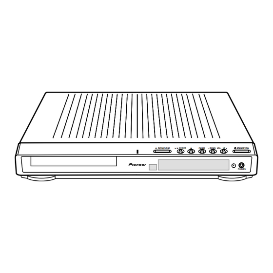
0 OPEN/CLOSE
6 DVD/CD
7
FM/AM
– DOWN
VOL.
UP +
STANDBY/ON
PHONES
XV-DV740
Regional restriction
codes (Region No.)
T-ZZK MAY 2004 printed in Japan
ORDER NO.
RRV2946
Remarks
Advertisement
Table of Contents
Troubleshooting

Related Manuals for Pioneer XV-DV740


Summary of Contents for Pioneer XV-DV740
- Page 1 PIONEER CORPORATION 4-1, Meguro 1-chome, Meguro-ku, Tokyo 153-8654, Japan PIONEER ELECTRONICS (USA) INC. P.O. Box 1760, Long Beach, CA 90801-1760, U.S.A. PIONEER EUROPE NV Haven 1087, Keetberglaan 1, 9120 Melsele, Belgium PIONEER ELECTRONICS ASIACENTRE PTE. LTD. 253 Alexandra Road, #04-01, Singapore 159936...
-
Page 2: Safety Information
PIONEER Service Manual. A subscription to, or additional copies Also test with plug reversed of, PIONEER Ser vice Manual may be obtained at a (Using AC adapter Earth nominal charge from PIONEER. plug as required) - Page 3 Fuji Photo Film Co. Ltd. • Also compatible with KODAK Picture CD This player supports the IEC's Super VCD stan- dard for superior picture quality, dual soundtracks, and widescreen support. VIDEO Super Video CD (Super VCD) XV-DV740...
-
Page 4: Table Of Contents
7.1.9 TROUBLE SHOOTING ......................... 96 7.1.10 DSP TROUBLE SHOOTING ....................... 99 7.1.11 DISASSEMBLY ..........................101 7.2 IC ................................110 7.3 EXPLANATION ............................113 7.3.1 SEQUENCE AFTER POWER ON ...................... 113 7.3.2 PROTECTION CIRCUIT ........................114 7.4 CLEANING............................. 118 8. PANEL FACILITIES ............................119 XV-DV740... -
Page 5: Specifications
(L = 1.5m)(XDE3046) (XXD3076) STANDBY/ON FM/AM L1/L2 TUNER LINE Yellow DISPLAY OPEN CLOSE RETURN DVD MENU TUNE+ ST– ENTER • AM Loop Antenna • Dry Cell Battery TUNE– MUTE SOUND (ATB7013) (R6P, AA) MASTER VOLUME TV CONTROL INPUT OPEN XV-DV740... -
Page 6: Exploded Views And Parts List
For the applying amount of lubricants or glue, follow the instructions in this manual. (In the case of no amount instructions, apply as you think it appropriate.) 2.1 PACKING 8, 14, 17 Front side XV-DV740... - Page 7 • • • • • • • • • • • • • • • • • • Operating Instructions XRC3147 (French) (2) CONTRAST TABLE XV-DV740/KUCXJ and XV-DV440/KCXJ are constructed the same except for the following : Mark Description XV-DV740/KUCXJ XV-DV440/KCXJ Operating Instructions XRE3084...
-
Page 8: Exterior Section
2.2 EXTERIOR SECTION Refer to "2.4 01 LOADER ASSY". Refer to "2.3 FRONT PANEL SECTION". XV-DV740... - Page 9 AEB7206 S Cover AEB7262 NSP 34 PCB Spacer (3x6) AEC7156 Locking Card Spacer AEC7372 (2) CONTRAST TABLE XV-DV740/KUCXJ and XV-DV440/KCXJ are constructed the same except for the following : Mark Description XV-DV740/KUCXJ XV-DV440/KCXJ CONTROL Assy XWZ3882 XWZ3896 Rear Panel XNC3298...
-
Page 10: Front Panel Section
2.3 FRONT PANEL SECTION XV-DV740... - Page 11 F.L Barrier XEC3055 Foot XMR3088 Display Window XAK3450 Front Panel See Contrast table (2) FUNC. Button XAD3185 (2) CONTRAST TABLE XV-DV740/KUCXJ and XV-DV440/KCXJ are constructed the same except for the following : Mark Description XV-DV740/KUCXJ XV-DV440/KCXJ Front Panel XMB3155 XMB3170 XV-DV740...
-
Page 12: Loader Assy
JGZ17P028FTC Screw VBA1094 Flexible Cable (24P) VDA1947 Tray VNL1920 Connector Assy 2P VKP2253 Floating Rubber VEB1351 Belt VEB1330 Stabilizer VNE2253 Loading Base VNL1917 Float Base DVD VNL1918 Drive Cam VNL1919 Gear Pulley VNL1921 Loading Gear VNL1922 Drive Gear VNL1923 XV-DV740... - Page 13 Rear View Daifree Daifree No. 23 No. 23 GEM1036 GEM1036 Tray Tray Concave of unevenness Concave of unevenness Inner side of a ditch Daifree GEM1036 Top View Bottom View Side of the rib Concave of unevenness Daifree Daifree GEM1036 GEM1036 XV-DV740...
-
Page 14: Traverse Mecha Assy-S
15 (Torque : 0.15 ± 0.01 N•m) Silicone Adhesive GEM1037 DVDM CN101 (Pickup Assy) 4 (Adjustment screw) Silicone Adhesive GEM1037 Screw Tight 15 (Torque : 0.15 ± 0.01 N•m) GYL1001 (Adjustment spring) To DVDM CN105 (Spindle Motor) DVDM CN104 (Stepping Motor) XV-DV740... - Page 15 Guide Bar VLL1514 Sub Guide Bar VLL1515 Leaf Spring VNC1023 Joint Spring VNC1019 Support Spring VNC1020 NSP 11 Mechanism Chassis VNE2248 • • • • • • Spacer VNL1913 Joint 03 VNL1949 Tapping Screw VBA1092 Screw BBZ20P050FTC Screw PMA26P100FTC XV-DV740...
-
Page 16: Block Diagram And Schematic Diagram
LINE 2 IN (OPT DIGITAL) CN5620 CN8011 IC8501 AK4114 DSPD56367PV150 IC8201 FM/AM TUNER DolbyDigital Decoder Dolby PrologicII DTS Decoder UNIT CN5701 DSP ASSY ATTENUATOR IC8401 LINE 1 IC3001 AK4529 - 6dB - 10dB INPUT BUFFER IC3003 SELECTOR TV IN CODEC XV-DV740... - Page 17 HP ASSY HEADPHONE 6CH AMP ASSY POWER AMP POWER MODULE SW MIX/GAIN ASSY(2/2) SPEAKER RELAY ANDREW IC3059 FL/FR FL/FR IC3301 STK402- IC3062 BD3814FV E-VOL Center CENTRE IC3401 6ch E-vol STK402- SL/SR SL/SR 3ch Power IC3056 IC3057 IC3058 JA3001 LINE XV-DV740...
-
Page 18: Loab Assy And Overall Wiring Diagram
POWER ASSY (XWZ3885) AC5V AC5V FLAC FLAC DVD ASSY (AXA7131) 1/3- DVDM ASSY (AWM7878) (RF) : RF SIGNAL ROUTE : FOCUS SERVO LOOP LINE : TRACKING SERVO LOOP LINE : STEPPING SERVO LOOP LINE LOAB ASSY (VWG2279) PICKUP ASSY-S (OXX8005) XV-DV740... - Page 19 52045-0545 52044-0545 AKN7003 HP L JA3001 GNDA AKP7050 HP R HP DET HP ASSY HP MUTE 5pinFFC (XWZ3869) 1/4- CONTROL ASSY (XWZ3882 : XV-DV740) (XWZ3896 : XV-DV440) CN5601 CN5611 52044-1545 52045-1545 VFDP XFLRST FLCS FLCK FLDATA DISPLAY ASSY VFL+5 (XWZ3874)
-
Page 20: Dvdm Assy(1/3)
3.3 DVDM ASSY(1/3) DVDM ASSY (AWM7878) XV-DV740... - Page 21 : FE DATA SIGNAL ROUTE : FOCUS SERVO LOOP LINE : TRACKING SERVO LOOP LINE : STEPPING SERVO LOOP LINE XV-DV740...
-
Page 22: Dvdm Assy(2/3)
3.4 DVDM ASSY(2/3) DVDM ASSY (AWM7878) XV-DV740... - Page 23 : S VIDEO SIGNAL ROUTE (Y) (PR/R) : VIDEO SIGNAL ROUTE (PR/R) (CY/G) : VIDEO SIGNAL ROUTE (CY/G) (PB/B) : VIDEO SIGNAL ROUTE (PB/B) : AUDIO SIGNAL ROUTE (DIGITAL) (C/V) (C/V) (CY/G) (C/V) (PB/B) (C/V) (CY/G) (CY/G) (PB/B) (PB/B) (PR/R) (PR/R) (PR/R) 10 11 XV-DV740...
-
Page 24: Dvdm Assy(3/3)
3.5 DVDM ASSY(3/3) DVDM ASSY (AWM7878) 1.8V Reg. 1.8V Reg. XV-DV740... - Page 25 : VIDEO SIGNAL ROUTE (C/V) : S VIDEO SIGNAL ROUTE (Y) : S VIDEO SIGNAL ROUTE (Y) (PR/R) : VIDEO SIGNAL ROUTE (PR/R) (CY/G) : VIDEO SIGNAL ROUTE (CY/G) (PB/B) : VIDEO SIGNAL ROUTE (PB/B) : AUDIO SIGNAL ROUTE (DIGITAL) XV-DV740...
-
Page 26: Dsp Assy (1/2)
X8201 stby GNDD P/SN DAUX XSS3003 R8220 XTL0 MCKO2 L8202 24.576MHz R8209 stby XTL1 BICK R8221 R8216 stby SDTO GNDD GNDD V5D1 L8204 L8203 QTL1013 QTL1013 GNDD MCLK LCKI R8340 R8322 100k IEDO R8320 100k IEIT R8321 100k GNDD XV-DV740... - Page 27 DSP ASSY CKSRYB104K16-T (FL) CKSRYB105K6R3-T : AUDIO SIGNAL ROUTE (Front L ch) (AWX8526) CEV***M**-T (SL) : AUDIO SIGNAL ROUTE (Surround L ch) RS1/16S***J-T : AUDIO SIGNAL ROUTE (Center ch) UNLESS OTHERWISE NOTED (SW) : AUDIO SIGNAL ROUTE (Sub Woofer ch) XV-DV740...
-
Page 28: Dsp Assy (2/2)
Level shifter TIO0 R8518 4.7k PB13 PB10 BCKO 96DTS R8519 LCKI GNDD BUSY 43 44 C8512 470p C8513 1394 LSSN R8526 GNDD R8809 GNDD CN8011 AKP7073 D8501 1SS355 Q8503 GNDD UN5112 Q8504 (2/2) UMD2N CN5618 Q8504 (1/2) UMD2N GNDD XV-DV740... - Page 29 BASIC MODEL NO USE C8550 AAC&96DTS NO USE R8541 MCACC YB 0.1 AAC&96DTS C8551 &MCACC X8501 VSS1171 CH470p 20MHz R8534 R8531 R8533 R8550 R8551 Q8501 (3/3) BASIC 0Ω 0Ω IC8502 MODEL TC7WU04FU DVD-A MCACC 0Ω 0Ω UN5212 1394 GNDD XV-DV740...
-
Page 30: 6Ch Amp Assy
3.8 6CH AMP ASSY 6CH AMP (AZW7283) CN3651 to FAN Motor CN3001 (FL) (SW) (SL) Non Distortion Circuit CN3002 XV-DV740... - Page 31 SEARCH : 2.3A AT NORMAL : 950mA 30PDA20-FC6 (FL) (SW) (SL) (FL) : AUDIO SIGNAL ROUTE (Front L ch) (SL) : AUDIO SIGNAL ROUTE (Surround L ch) : AUDIO SIGNAL ROUTE (Center ch) (SW) : AUDIO SIGNAL ROUTE (Sub Woofer ch) XV-DV740...
-
Page 32: Control(1/4), Trade3 And Trade2 Assys
DSPSS (DVD) (DVD) DSPSS (DVDL) (DVDL) RECL XDSPRST DSPRST DSPCLK DSPCLK DSPDO DSPDO DSPDI DSPDI DECMUTE DECMUTE MODC MODC DSP MUTE DSP MUTE XDSPMUTE MUTE OUT MUTE OUT DSPAOUT CN5618 CN5619 CN5620 AKP7062 AKP7062 AKP7073 TRADE 3 ASSY (XWZ3868) XV-DV740... - Page 33 : AUDIO SIGNAL ROUTE (L ch) CONTROL ASSY (DVD) : AUDIO SIGNAL ROUTE (DVD Lch) (XWZ3882 : XV-DV740) : AUDIO SIGNAL ROUTE (DIGITAL) (FL) : AUDIO SIGNAL ROUTE (Front L ch) (XWZ3896 : XV-DV440) VE+5 VFL+5 (SL) : AUDIO SIGNAL ROUTE (Surround L ch)
-
Page 34: Control Assy(2/4)
3.3k DSP MUTE GNDA Q3071 GNDD DTA124EUA Difference of the Andrew circuit GNDD All resistors are : RS1/16***J-T DSPMUTE All capacitors are : CKSRYB***K**-T VA-12 XV-DV740 XV-DV440 XV-DV740 XV-DV440 Wiring Wiring VA-12 KUCXJ KCXJ KUCXJ KCXJ R3107 C3141 0.018/25 4.3k 5.6k... - Page 35 CONTROL ASSY (XWZ3882 : XV-DV740) (XWZ3896 : XV-DV440) VA+12 ANDREW CIRCUIT C3143 STBY R3103 STBY R3155 R3157 BA4558F IC3056 (1/2) C3141 (FL) R3703 C3189 10/16 Q3067 R3159 R3153 STBY STBY R3162 8.2k STBY GNDD R3161 STBY R3154 Q3067 STBY R3160 STBY 8.2k...
-
Page 36: Control Assy(3/4)
R3006 STBY R3014 SELECTOR (FL) R3007 C3017 R3015 10/50 L3007 1.8k Q3001 STBY R3021 R3009 4.7k STBY 2SD2114K(VW) STBY L3009 Q3002 R3022 4.7k GNDA GNDS L3008 STBY 2SD2114K(VW) C3018 R3016 R3008 1.8k 10/50 GNDA REC MUTE VE+56 VA-12 GNDA XV-DV740... - Page 37 CONTROL ASSY (XWZ3882 : XV-DV740) (XWZ3896 : XV-DV440) 1/4, 4/4 VA+12 6dB ATT 10dB ATT IC3003 C3019 BA4558F 10/50 (FL) C3037 VA+5 W395 R3023 10/50 1.5k VA+5 (1/2) Q3005 Q3009 2SC4081(QR) 2SC4081(QR) R3047 R3031 LIN1 (1/2) (1/2) VA+12 Q3006 2SC4081(QR)
-
Page 38: Control Assy(4/4) And Hp Assys
3.12 CONTROL ASSY(4/4) and HP ASSYS CONTROL ASSY (XWZ3882 : XV-DV740) (XWZ3896 : XV-DV440) VD+5 Q3906 2SA1576A(QR) STBY Q3065 DTA124EUA R3918 GNDD VA-12 HPAC1 VA-12 GNDD HPAC VA+12 D3901 DAP202K-TLB IC3901 CN3902 NJM4565M R3935 C3919 (FL) 52045-0545 47/16 (FL) (FL) - Page 39 MA111 Q5577 VE+5 2SA1037K(QR) GNDD GNDU VE+5 GNDU VE+5 R5492 R8883 R5494 Q5576 100k 2SA1037K(QR) Q5575 SR TXD DTC124EUA D5571 Q5579 MA111 DTC124EUA GNDU GNDU REMOCON R5496 GNDU :FLch AUDIO SIGNAL ROUTE (FL) :DIGITAL AUDIO SIGNAL ROUTE GNDU GNDU XV-DV740...
-
Page 40: Power Assy(1/2)
MUTEC MUTE FLIN Guard GND GNDA R133 FRIN R9504 R9501 SWIN STBY R9505 SLIN R9503 GNDX SRIN GNDA GNDD Thermal sensor VPR+8 W125 CKT for D11 VPR+8 DVDPOWER VA-12 CN5521 CN5522 to TRADE2 ASSY CN5521 to TRADE2 ASSY CN5522 XV-DV740... - Page 41 STBY C8884 STBY GNDD C9901 STBY CHASSISGND CN901 • NOTE FOR FUSE REPLACEMENT from DVDM ASSY CAUTION - FOR CONTINUED PROTECTION AGAINST RISK OF FIRE. :AUDIO SIGNAL ROUTE REPLACE WITH SAME TYPE AND RATINGS OF FUSE. :VIDEO SIGNAL ROUTE XV-DV740...
-
Page 42: Power Assy(2/2) And Trade1 Assys
GNDV R9904 (PB/B) R8832 Cb/B Y1out STBY GNDV F8831 C8831 150 (F) (PR/R) R9905 STBY XCH3017 Cr/R STBY 1000/6.3 R8841 GNDV Y(S) 150 (F) R9906 Cout STBY F8841 GNDV STBY (C/V) R8842 R9907 STBY 150 (F) GNDV R9908 STBY XV-DV740... - Page 43 GNDREG GNDREG XPROTECT XPROTECT TUNER TUNER VD+5 VD+5 VA-12 VA-12 CN8802 VP+15 VP+15 AKP7179 VFL+5 VFL+5 MUTEC SENSE+8 MUTE MUTEC FLIN MUTE GNDA FLIN GNDA FRIN FRIN SWIN SWIN SLIN SLIN SRIN Chassis SRIN GNDA VPR+8 VPR+8 VPR+8 VPR+8 XV-DV740...
-
Page 44: Video Assy
75 (F) STBY Y2out R8954 Cb(D) STBY R8961 R8963 STBY 75 (F) Cbout (Cb) C8961 470/6.3 R8964 R8962 STBY STBY Cr(D) R8973 R8971 Crout (Cr) C8971 STBY 75 (F) 470/6.3 R8974 R8972 STBY STBY GNDV (CY/G) GNDV (PB/B) GNDV (PR/R) XV-DV740... - Page 45 JA8951 VKB1150 L8951 Y(Green) VTL1086 YGND (Blue) L8961 CbGND VTL1089 (Red) CrGND L8971 VTL1089 (PR/R) : VIDEO SIGNAL ROUTE (PR/R) (CY/G) : VIDEO SIGNAL ROUTE (CY/G) (PB/B) : VIDEO SIGNAL ROUTE (PB/B) GNDS XV-DV740...
-
Page 46: Dispaly Assy
0.022 61 60 57 56 52 51 VE+5 IC5601 PT6302LQ-003 5951 FL DRIVER Vout GP1UM27XK 23 24 26 27 CN5601 52044-1545 GNDLED TIMERLED VE+5 REMOCON KEY1 FLAC1 FLAC2 C5681 GNDFL 0.01 VFL+5 FLDATA FLCK FLCS XFLRST VFDP VFDP GNDFL XV-DV740... -
Page 47: Power Led
ALL INDUCTORS ARE IN µH DISPLAY ASSY S5921 : STANDBY/ON LAU***J S5922 : UP + VOLUME S5923 : – DOWN NO MARK DIODE S5924 : FM/AM S5925 : 7 (STOP) 1SS133 S5926 : 6 DVD/CD (PLAY/PAUSE) S5927 : 0 OPEN/CLOSE XV-DV740... -
Page 48: Waveforms
IC501 - pin 26 [S Video out-C] V: 1V/div. H: 10µsec/div. IC501 - pin 20 [Component Video out-Y] V: 1V/div. H: 10µsec/div. IC501 - pin 18 [Component Video out-Pb] V: 2V/div. H: 10µsec/div. IC501 - pin 16 [Component Video out-Pr] V: 2V/div. H: 10µsec/div. XV-DV740... -
Page 49: Pcb Connection Diagram
Resistor array 3-terminal regulator 4.1 LOAB ASSY SIDE A SIDE B LOAB ASSY LOAB ASSY VNP1836-C LOAB PNE-1B1 S101 LOAD+ VWG2279- CN602 C102 LOAD- CN602 VWG2346- C101 CN601 (VNP1836-C) (VNP1836-C) CN601 CN602 CN601 CN601 CN602 CN103 LOADING MOTOR ASSY XV-DV740... -
Page 50: Dvdm Assy
C734 R663 Q726 Q726 C422 R662 R732 R726 R619 R725 C733 IC601 R611 R421 IC601 C1562 R562 R618 R561 IC421 C684 R1081 C671 CONTACT R617 R1069 C659 SIDE R616 (L600) C561 CN607 C698 R600 C605 R603 R602 (ANP7463-B) CN8801 XV-DV740... - Page 51 C643 C639 IC603 R543 C603 R1049 IC603 R522 R972 R523 ICT FC R973 R974 R604 R502 C571 R503 R571 R513 C562 C521 C563 R521 Q977 Q521 C501 Q501 R501 R9521 Q521 C511 Q511 R9501 Q501 R511 R9511 Q511 (ANP7463-B) XV-DV740...
-
Page 52: Dsp Assy
4.3 DSP ASSY SIDE A SIDE A DSP ASSY (ANP2022-B) XV-DV740... - Page 53 R8515 C8544 R8523 C8520 R8309 C8518 C8542 R8310 C8521 R8311 C8540 R8528 R8312 R8313 R8529 R8314 C8539 R8326 C8538 C8529 C8534 C8535 R8537 L8502 R8603 L8602 C8531 R8801 R8812 R8811 R8813 R8602 C8014 C8013 C8606 C8605 C8608 C8607 (ANP2022-B) XV-DV740...
-
Page 54: 6Ch Amp Assy
4.4 6CH AMP ASSY SIDE A SIDE A DC FAN MOTOR 6CH AMP ASSY CN3651 Q3384 CN3011 Q3383 IC3303 IC71 IC3301 CN3012 Q3654 IC81 IC3401 (ANP7461-A) XV-DV740... - Page 55 Q3532 Q3534 Q3332 Q3334 IC3301 Q3331 Q3333 Q102 Q3651 Q101 Q3653 Q106 Q103 Q107 Q3652 Q104 Q111 Q121 Q3433 Q3431 IC3401 Q3301 Q3371 Q3302 Q3372 Q3434 Q3432 Q3504 Q3502 Q3572 Q3401 Q3471 Q3533 Q3531 Q3402 Q3472 Q3501 Q3571 (ANP7461-A) XV-DV740...
-
Page 56: Control Assy
C3190 W196 C3150 W214 W197 W212 W427 C3149 W198 W204 W206 W202 W164 C3906 W174 W177 W175 W126 W130 C3912 C3918 C3917 CONTACT SIDE C3923 CN3902 C3920 KN5501 W101 C3919 W104 W102 W103 CN5611 CONTACT SIDE CN3902 CN5611 CN3901 XV-DV740... - Page 57 W227 XWZ3892 W228 XWZ3864 XWZ3896 XWZ3881 W226 XWZ3865 XWZ3898 XWZ3882 W188 XWZ3866 XWZ3883 W187 XWZ3867 XWZ3884 W174 KN5791 XWZ3878 XWZ3886 W177 W175 W185 XWZ3887 W145 XWZ3888 W126 XWZ3889 W130 W437 W147 W438 W439 W440 W106 W107 (XNP3083-B) 5611 CN5601 XV-DV740...
- Page 58 UTEST Q5578 R5563 R5561 R5565 Q5575 R5555 Q5579 Q3173 XWZ3862 XWZ3863 XWZ3864 XWZ3865 C5508 XWZ3866 R5590 XWZ3867 XWZ3878 Q5501 XWZ3879 R5510 XWZ3880 R5519 XWZ3881 XWZ3882 Q5572 XWZ3883 XWZ3884 Q5571 XWZ3886 XWZ3887 XWZ3888 Q8307 Q3003 XWZ3889 XWZ3890 XWZ3892 XWZ3896 XWZ3898 XV-DV740...
- Page 59 VFL+5 Q5501 IC3901 VFDP GNDFL R5584 FLAC2 R5590 10.FLAC1 MUTE Q5572 SUBAC GNDD Q5501 Q5571 VE+56 IC3901 GNDD GNDU Q5595 GNDD 5.DOUT 1.NC Q5572 R5596 Q8307 Q3003 Q3908 Q5595 Q3907 R3936 D3901 Q3908 Q3907 R3939 R3940 (XNP3083-B) CN5611 CN3902 XV-DV740...
-
Page 60: Trade2,Trade3 And Hp Assys
TRADE2 ASSY XWX3071 CONTROL CN5511 CN5512 (XNP3070-B) CN5511 CN5512 CN5501 CN5502 HP ASSY PCB BINDER CONTACT SIDE 1.HP MUTE 2.HPDET 3.HP R CN3901 3901 4.GNDHP 5.HP L CN3902 W442 W443 HP ASSY XWZ3869 (XNP3083-B) G H I G H I XV-DV740... - Page 61 CN5522 CN5521 Q114 XWX3071 TRADE2 ASSY Q115 Q115 CN5511 CN5512 (XNP3070-B) CN5512 CN5511 HP ASSY CN3901 Q3921 R3919 C B E Q3901 CN3901 E B C Q3903 (XNP3083-B) Q3921 Q3903 G H I G H I Q3922 Q3901 Q3902 XV-DV740...
-
Page 62: Power Assy
GNDSL C3631 C3633 W134 W133 AC IN W130 W129 RISK OF FIRE REPLACE FUSE AS MARKED. IC51 PRODUCTIO W124 C8821 GNDV CN8807 CN8801 CONTACT CN8803 CONTACT SIDE SIDE W116 5 pin CONTACT SIDE 9 pin CN8801 CN8807 CN8001 CN903 XV-DV740... - Page 63 DVDMUTE PCB BINDER 2SB1565(EF) VEF1040- W152 V+12 NJM78M56FA 94V-0 W137 GNDD CN5102 IC51 CN901 W132 PRODUCTION CODE W138 W139 W124 GNDV POWER ASSY XWZ3870 W806 XWZ3871 W807 XWZ3885 W805 CN8801 XWZ3873 W808 XWZ3872 W811 XWZ3893 W812 CN8801 (XNP3084-B) CN903 XV-DV740...
- Page 64 GNDV 9.GNDD 18.DVDPOWER 17.XDVDRST 8.VDET 16.SYS_CS1 7.NC 15.SYS_CS2 6.DVDMUTE 14.SCLK 5.WAKEUP 13.SDATA 4.TXD 12.MDATA 3.RXD GNDD 11.ACK 2.RTS 10.GNDD 1.CTS CN5102 GNDC 94V-0 POWER ASSY XWZ3870 W806 XWZ3871 W807 XWZ3885 W805 XWZ3873 W808 CN8801 XWZ3872 W811 XWZ3893 W812 CN8801 XV-DV740...
- Page 65 Q3637 GNDSR Q3611 Q3638 Q3611 D3613 Q3639 Q3640 GNDSL R3630 R3615 D3635 NEUTRAL LIVE PRIMARY VD+5 GNDD GNDV 0 1 2 3 0 1 2 3 4 5 6 7 8 9 CN8803 CN8807 CN8801 CN8807 (XNP3084-B) CN8803 CN8801 XV-DV740...
-
Page 66: Trade1, Video And Display Assys
4.8 TRADE1, VIDEO and DISPLAY ASSYS SIDE A TRADE 1 ASSY CN3001 CN3002 CN3011 CN3012 IC24 IC25 CN3021 CN3022 (XNP3084-B) CN3031 CN3032 DISPLAY ASSY OPN/CLS PLAY/PAUSE S5926 S5927 W506 V5601 5951 DISPLAY ASSY XWZ3874 94V-0 CN5601 XV-DV740... - Page 67 SIDE A VIDEO ASSY (XNP3084-B) VOL DOWN VOL UP POWER ON LAY/PAUSE STOP BAND S5926 S5925 S5924 S5923 S5922 S5921 V5601 D5931 C5680 C5678 D5662 (XNP3084-B) XV-DV740...
- Page 68 C8872 R8861 L8961 R8853 R8876 R8866 R8975 R8862 R8854 C8962 R8875 R8865 R8980 R8966 R8851 R8981 R8965 94V-0 VIDEO ASSY XWZ3875 XWZ3891 (XNP3084-B) DISPLAY ASSY POWER ON VOL UP BAND STOP VOL DOWN DISPLAY ASSY XWZ3874 94V-0 Q5691 IC5601 XV-DV740...
- Page 69 ATTENTION_ REMPLACER LE IC LINKS COMME INDIQUE DE CHEZ LITTELFUSE INC. (XNP3084-B) CN3022 CN3021 IC24 IC25 1.NC GNDLED TIMERLED VE+5 PLAY/PAUSE OPN/CLS STOP 5.REMOCON FLAC1 FLCS FLAC2 XFLRST GNDFL 15.VFDP 10.VFL+5 FLDATA FLCLK GNDFL CN5601 (XNP3084-B) IC5601 Q5692 Q5693 XV-DV740...
-
Page 70: Pcb Parts List
RS1/16S471J RS1/16S122J R3157, R3158 RS1/16S562J RS1/16S362J Mark No. Description Part No. Mark No. Description Part No. > IC421 PQ018EH01ZP PARTS LIST FOR XV-DV740 > IC411 PQ018EZ01ZP LOAB ASSY > IC441 PQ20WZ11 SWITCHES AND RELAYS > IC401 R1224N102H S101 VSK1011 IC601... - Page 71 L8504,L8701,L8702 QTL1013 C126, C346 CKSRYB223K50 CHIP SOLID INDUCTOR C202, C205, C212, C215 CKSRYB472K50 C402, C403, C405, C409 (10uF/16V) DCH1165 CAPACITORS C8209,C8210 CCSRCH100D50 RESISTORS C8421 CCSRCH101J50 R201 RAB4C220J C8007,C8008,C8201,C8212,C8214 CCSRCH471J50 R211 RAB4C390J C8404,C8409-C8414,C8416,C8417 CCSRCH471J50 R100, R1011-R1013,R111, R210 RS1/10S0R0J C8419,C8505,C8507,C8509 CCSRCH471J50 XV-DV740...
- Page 72 RN1901 CN3651 2P PLUG KM200SA2 Q101, Q103 UMB1N Q102, Q104 UMH1N > D3321-D3326 1SR139-400 CONTROL ASSY D3327,D3328 1SR139-400 SEMICONDUCTORS > D3421-D3426 1SR139-400 IC3003,IC3051-IC3053,IC3055-IC3058 BA4558F-HT D3427,D3428 1SR139-400 IC3062 BD3814FV D3387,D3388,D3651-D3655 1SS133 IC3901 NJM4565M D101, D102, D104, D3657,D42 1SS355 IC5501 PDC114B XV-DV740...
- Page 73 C3069,C3070 CEJQ100M16 All Resistors RS1/16S###J C3035,C3036 CEJQ100M35 C5595,C5596 CEJQ220M25 OTHERS CN5511,CN5512,CN5521,CN5522 AKP7075 C3065,C3066 CEJQ470M16 23P SOCKET C5504,C5789,C5793,C5795 CKSRYB102K50 C3025,C3026,C3033,C3034 CKSRYB103K50 C3067,C3068,C3083,C3084 CKSRYB103K50 C3091,C3092,C3115,C3116 CKSRYB103K50 HP ASSY SEMICONDUCTORS C3147,C3148,C3159,C3160 CKSRYB103K50 C3169-C3172,C5506,C5508,C5571 CKSRYB103K50 Q3903 DTA124EUA C5573,C5580,C5794,C5798,C5799 CKSRYB103K50 Q3901,Q3921 XP4506 C3121-C3124,C3180,C3182,C3186 CKSRYB104K16 XV-DV740...
- Page 74 CN8003 7P FFC CONNECTOR VKN1267 TRANSFORMERS KN1, KN2 WRAPPING TERMINAL VNF1084 > ATT7079 JA3301 6CH SPEAKER JACK XKE3021 > AN1 AC INLET 1P XKP3042 SWITCHES AND RELAYS D. HEAT SINK XNH3030 RY3641-RY3643 ASR7017 > XSR3008 TRADE 1 ASSY CAPACITORS XV-DV740...
- Page 75 SWITCHES AND RELAYS S5921-S5927 VSG1024 CAPACITORS C5674 CCSRCH470J50 C5661,C5663 CCSRCH471J50 C5564 CEAL101M6R3 C5679,C5680 CEAL1R0M50 C5678 CEAL220M35 C5953 CEAL470M16 C5671-C5673 CKSRYB102K50 C5677,C5681 CKSRYB103K50 C5562,C5563,C5665,C5666,C5675 CKSRYB223K50 C5952 CKSRYB223K50 C5676 CHIP VARISTOR VCX1001 RESISTORS All Resistors RS1/16S###J OTHERS CN5601 15P FFC CONNECTOR 52044-1545 XV-DV740...
-
Page 76: Adjustment
[Electrical Part] screw screw Electrical adjustments are not required. 6.2 JIGS AND MEASURING INSTRUMENTS Test mode remote control Screwdriver (large) Screwdriver (medium) TV monitor unit (GGF1381) Screw tight (GYL1001) DVD test disc Precise screwdriver Soldering iron (GGV1025) XV-DV740... -
Page 77: Necessary Adjustment Points
Exchange the Traverse Mechanism point Electric point ∗ After adjustment, screw locks Mechanical Ÿ Exchange the Spindle Motor point with the Screw tight. Electric point Exchange PCB Assy Mechanical Exchange PC Board point LOAB and DVDM ASSY Electric point XV-DV740... -
Page 78: Test Mode
Perform only trace, video and audio outputs are nothing. < When playback with the target address of disc (DVD)> For example, when playback with # 30000 CHP/TIM During PLAY Press keys in order 030000 TEST MODE: OFF POWER GGF1381 Test mode remote control unit XV-DV740... -
Page 79: Mechanism Adjustment
(Refer to "6.1 ADJUSTMENT ITEMS AND LOCATION".) Spacer for Height adjustment Note: Turn a flat side Before removing the flexible cable for the into bottom pickup, soldering of the pickup circuit is necessary. For details, see "7.1.11 DISASSEMBLY". XV-DV740... - Page 80 J : Min J : Min If error rate is OK, Disc playback normally. locks a root of • The measurement of block error rate tangential and radial adjustment screws with the Screw tight. Screw tight: GYL1001 Test mode end XV-DV740...
-
Page 81: General Information
Perform only trace, video and audio outputs are nothing. = Screen display ON/OFF 1. Turn off the display by pressing the [AUDIO] (A8-1E) key of the remote control unit. 2. Turn on the display by pressing the [DISPLAY] (A8-43) key of the remote control unit. XV-DV740... - Page 82 • After the search, perform only trace and video and audio outputs are nothing. 4. Release the Search address input • Clear the address by pressing the [CLEAR] (A8-45) key. Release the address input mode when pressing the [CLEAR] key once again. XV-DV740...
-
Page 83: Display Specifications Of The Test Mode
Kinds of version / firmware of the FE. Scart terminal output [SK – ∗ ∗] RAM or ROM (Display only the WY model which can do the output setting of scart terminal.) VIDEO : [00] S-VIDEO : [01] : [02] XV-DV740... -
Page 84: Functional Specification Of The Shortcut Key
• Region confirmation mode (ESC + AUDIO [Test mode remote control unit] + "1"-"8" [Test mode remote control unit] keys) After you press the AUDIO key while holding the ESC key pressed and then input the region number, if the number is different from that set in the unit, an error message is displayed, and the tray opens. XV-DV740... -
Page 85: Specification Of Model Information Display
(version of ST core software) softwareVersion . softwareRevision / buildNumber 0 F.E VERSION Version of FRONT END (version of mechanism controller CHIP software) MainVersion / Kinds of firmware RAM or ROM - Remote control code = Key code of Main unit XV-DV740... -
Page 86: Functional Specification Of The Service Mode
00 0 0 0 01 0 0 1 02 0 1 0 03 0 1 1 04 1 0 0 05 1 0 1 06 1 1 0 07 1 1 1 Character in bold : Item name : Information display XV-DV740... -
Page 87: Mechanical Error History
PLL lost timeout 0x93 DECODER ERROR 0xa∗ DECODER TIMEOUT 0xb∗ Note : 0 x & & ID lost error 0xa3 ID lost timeout 0xb3 DEVICE ERROR 0xd∗ code SRAM error 0xd1 (Only this part is displayed to a display) XV-DV740... - Page 88 Do move to inner and outer periphery 1. Stepping motor of the stepping in the test mode? 2. Inside switch Stepping move timeout 0 x 54 Did timeout at stepping movement Do indicate "S-04" at the most inner 3. Driver periphery of the stepping? XV-DV740...
- Page 89 SRAM error 0 x d1 Cannot access SRAM 2. Front End IC Is not bus line short-circuiting? 3. Front End-SRAM bus line FAILSAFE (0 x e∗) 1. software runaway Unexpected error 0 x e1 Unexpected error 3. Software bug XV-DV740...
- Page 90 DVD/CD S E R V I C E LINE2 S E R V I C E TUNER S E R V I C E S E R V I C E LINE1 S E R V I C E XV-DV740...
- Page 91 Refer to "7.1.10 DSP TROUBLE SHOOTING". Service Test mode connecting point Connecting point CONTROL ASSY DSP MUTE 1.MUTE OUT R5566 R5531 R5547 R5526 TEST TEST SIDE B R5546 C5510 UTEST R5563 R5561 R5555 Q3173 C5508 R5510 R5519 SIDE B Q5571 XV-DV740...
-
Page 92: Id Number And Data Setting
ID number. 0 0 0 0 0 0 0 0 1 Note: If you press the PLAY button before inputting a 9-digit ID number, the unit returns to Step 2 without doing anything <PLAY> Enter else. Input ID Number ! XV-DV740... - Page 93 [Player's ID Number Setting] ID Number ? [ 0 0 0 0 0 0 0 0 1 ] Compare > 0 0 0 0 0 0 0 0 1 OK? <PLAY> Enter <STOP> Memory Clear Input ID Number ! XV-DV740...
- Page 94 • Indication when the data have not been set If no ID data are set after the ID number is changed, the message "NO ID DATA" flashes on the screen and FL display for a few seconds after the power is turned on or during Stop mode. XV-DV740...
-
Page 95: Method For Diagnosing Degradation Of The Lds On The Pickup Assy
1.5 V or higher, the 780-nm LD is degraded. PICKUP ASSY DVDM ASSY CN101 CN101 CN104 CN121 R102 R101 V+5D IC201 GNDD R220 R221 (650) (780) R222 Q201 Q211 C222 R223 R202 R212 R391 C306 Front side SIDE A XV-DV740... -
Page 96: Trouble Shooting
Pins 18 of the KEY input terminal is 5 V. If it is All operation keys are disabled. has already been pressed. not, check if the operation switch on the line is in failure. * Vdd= Approx. 5V (depending on the unit) ex.) 0.85Vdd= 0.85 × 5 (V) = 4.25 (V) XV-DV740... -
Page 97: Dvd Section
(An opening screen is LOADING SW (LOAB S101) displayed on the monitor) • Is a LOAD-DRVC signal reaching ? BACK END IC (DVDM IC601) • Does the voltage of CN105 pin 1 change by pressing the Inside switch. Inside switch XV-DV740... - Page 98 Are there scratches or dirt on the disc ? Disc playback Is there a problem with the format of the disc? Disc (block noise, freeze, other) No sound (Picture is normal) Is signal output from DOUT signal (CN901-pin 21) on the DVDM Assy ? DVDM CN901-pin 21 XV-DV740...
-
Page 99: Dsp Trouble Shooting
When the analog audio output of a DSP module is unusual but the above error information is not displayed, the fault is probably in the CODEC IC (IC8401) and the peripheral circuits. As the µ-com has not received data from the CODEC IC, it cannot detect the fault and display the error information. XV-DV740... - Page 100 DSPHREQ CCLK IC8201 DECMUTE DECMUTE CDTI DIRERR DIRERR Level Shifter CDTO INT0 * This connection diagram displays the connection between the U-com, DSP, DIR and CODEC. IC8401 CCLK The pin order is different from the true assignment. CODEC CDTI XV-DV740...
-
Page 101: Disassembly
(The test disc is clamped.) Press the STANDBY/ON button to turn off the power. Pull out the power cord from the outlet. Test disc Slit Tray open Tray Screwdriver (small) Tray panel Screwdriver (small) Projection Drive cam 01 LOADER Assy Bottom view XV-DV740... - Page 102 Remove the two screws. Disconnect the one flexible cable. Disconnect the two connectors. Remove the CONTROL Assy. CONTROL Assy Bottom view CN5701 CN5501 CN5502 CONTROL Assy CN5611 CN3902 Front panel section XV-DV740...
- Page 103 IC8401 : AK4529VQ R8415 : 4.7Ω If the above parts are damaged, the audio signal can not be output. DSP Assy Rear panel DSP holder Lead wire Jig cable (GGD1266) ×2 CONTROL Assy 6CH AMP Front panel section Diagnosis XV-DV740...
- Page 104 Connect the two jig cables. Jig cable (GGD1160) Lead wire CONTROL Assy (for ground) Jig cable (GGD1266) ×2 6CH AMP CN8801 CN5102 CN923 POWER Assy CN901 01 LOADER Assy Front panel section (reverse state) Spacer DVDM Assy Spacer Spacer Jig cable (GGD1222) Diagnosis XV-DV740...
- Page 105 *1 : To protect from the electrostatic resisting pressure. Tray Drive Cam Note when reinserting the Tray When reinserting the Tray, first align the triangle printed on the Loading Base and the pin of the Drive Cam, then insert the Tray. Front Side Loading Base Triangle XV-DV740...
- Page 106 Dislodge the flexible cables from their packaged for the spindle motor Front Side placement. Flexible cable Flexible cable for the pickup for the stepping motor Bottom View Remove the four hooks. Traverse Mecha. Assy-S × 2 Remove the Traverse Mecha. Assy-S. × 2 XV-DV740...
- Page 107 Remove the flexible cable for the pickup. Flexible cable for the pickup Bottom View Adjustment screw Adjustment screw (Skew screw) Remove the two skew screws and two skew springs. (Skew screw) Remove the Pickup Assy-S. Pickup Assy-S Skew spring Skew spring XV-DV740...
- Page 108 Joint Spring Silicone Adhesive GEM1037 Joint 03 Silicone Adhesive GEM1037 Arrangement of the flexible cable Arrangement of the flexible cable for the spindle motor for the stepping motor : Conductive surface : Conductive surface Hook Hook Bottom View Bottom View XV-DV740...
- Page 109 Reference line Hook Fold the flexible cable as indicated in the photo Fold the flexible cable along the hook Hook the part folded in Step 1 to the hook Reference Hook Pass the cable below the hook line Hook XV-DV740...
- Page 110 XRECMUTE REC OUTPUT MUTE ON/OFF XMUTEC Cch MUTE ON/OFF REAR RELAY ON/OFF RYFSC FRONT/SW/CENTER RELAY ON/OFF 3/5 v convert control for SR+ function (3/5CONVERT) TIMERLED Control TIMER LED LEVELSHIFT VOL 0 to 5 : H VSS4 VSS4 VDD4 VDD4 XV-DV740...
- Page 111 WIRE LESS OUTPUT SELECT A INPUTSELB AUDIO INPUT SELECT B INPUTSELA AUDIO INPUT SELECT A XTL0 Selection X'tal to DIR DIRERR LOCK/UNLOCK from DIR DIRRST Reset to DIR /CODEC DIRCS Chip select to DIR/CODEC PB7/D7 DIRDO Data input from DIR/CODEC XV-DV740...
- Page 112 • PortE and PortF can be selected for input or output by each 2 bits. • In case of without RDS, it is best that RDSDATA and RDSCLK are assigned as I/O port which can be set output and output low level. XV-DV740...
-
Page 113: Explanation
• If no pulse is input to the AC terminal (Pin 4) for about 60 msec when the microcomputer is in Memory Backup mode, it will not do any processing. • The unit will recover from Memory Backup mode if a reset command is input to the XRESET terminal (Pin 8). XV-DV740... -
Page 114: Protection Circuit
1.83 ohms or less, Q3601 begins to operate, Q3639 is turned on, Q3640 (E, C, and B)is turned on, and the level of XPROTECT becomes MID. → The microcomputer detects the XPROTECT level and shuts the power to the unit off. XV-DV740... - Page 115 Q106 is turned on, and the level of the XPROTECT line becomes D3658, Q3651 (E, C, B) is turned off, Q3651 (E2, B2, C2) is low. ← The microcomputer detects the XPROTECT level and shuts turned on, and the level of XPROTECT becomes low. the power to the unit off. XV-DV740...
- Page 116 Q111 on, and the level of the XPROTECT line becomes low. The microcomputer detects the XPROTECT level (2) When negative (-) DC voltage was generated at the SP and shuts the power to the unit off. terminal Q3638 is turned on, and XPROTECT is activated. XV-DV740...
- Page 117 (2) When the VDET signal to the microcomputer is interrupted because of defective soldering of the 30-pin connector or incomplete insertion of FFC → The VDET level is lowered by the pull-down resistor (1 Mohms) on the side of the microcomputer. XV-DV740...
-
Page 118: Cleaning
Before shipping out the product, be sure to clean the following positions by using the prescribed cleaning tools: Position to be cleaned Cleaning tools Pickup lenses Cleaning liquid : GEM1004 Cleaning paper : GED-008 Position to be cleaned Cleaning tools Fans Cleaning paper : GED-008 XV-DV740... -
Page 119: Panel Facilities
Press to switch to the tuner function, then to toggle between the FM and AM bands. VOLUME buttons Use to adjust the volume. STANDBY/ON Press to switch the system on or into standby. PHONES jack Headphone jack. Timer indicator Lights when the wake-up timer is set. XV-DV740... - Page 120 Lights when the wake-up timer is set. Lights during multi-angle scenes on a DVD disc. Lights when the sleep timer is active. 11 2 PRO LOGIC II Lights during Dolby Pro Logic II decoding. 12 2 DIGITAL Lights during playback of a Dolby Digital source. XV-DV740...
-
Page 121: Remote Control
Press to switch the system on or into standby. Use to select channels on the TV. Function select buttons VOL +/– Press to select the source you want to listen to Use to adjust the volume on the TV. (DVD (CD). TUNER, TV, LINE) XV-DV740... - Page 122 Use to display the top menu of a DVD disc in the play position (this may be the same as pressing DVD MENU). HOME MENU Press to display (or exit) the on-screen menu for Initial Settings, Play Mode functions, etc. XV-DV740...
-
Page 123: Plasma Display
CONTROL IN jack of this unit plasma display through a media receiver to the CONTROL If you have a Pioneer plasma display (models OUT jack of your plasma display. PRO-1110HD, PRO-910HD, PDP-5040HD and Before you can use the extra SR+ features, you PDP-4340HD), you can use an SR+ cable (see need to make a few settings in the unit. -
Page 124: Jigs List
DVD Data Disc GGV1133 (*) diagnosis (ID data setting) DVD Data Disc GGV1174 (*) diagnosis (ID data setting) (*) : GGV1133 is now released, however GGV1174 will be released in MAY/2004. Until GGV1174 is released, use GGV1133 data disc. XV-DV740...
Need help?
Do you have a question about the XV-DV740 and is the answer not in the manual?
Questions and answers