Table of Contents
Advertisement
Advertisement
Table of Contents

Related Manuals for Gilson Test-Master TM-6


Summary of Contents for Gilson Test-Master TM-6
-
Page 1: Diagram
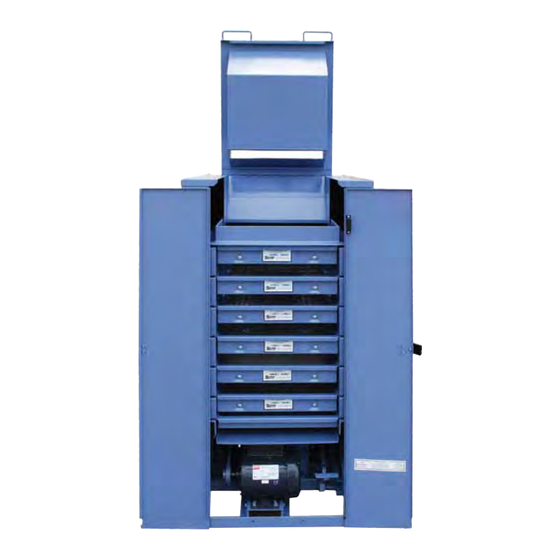
Operating Manual gilson test-Master® testing Screens tM-5 & tM-6 Rev: 04/12/2013 pHOne: 800-444-1508 FaX: P.O. Box 200, Lewis Center, Ohio 43035-0200 800-255-5314 740-548-7298 e-mail: customerservice@gilsonco.com Website: www.globalgilson.com 740-548-5314... -
Page 2: Safety Instructions
Gilson Company, Inc. Gilson Test-Master Testing Screen: TM-5 & TM-6 ® SaFetY inStruCtiOnS Whether you are the owner, employer, operator, or maintenance person for this machine, safety is your responsibil- ity. You are responsible for operating and maintaining this equipment in compliance with these instructions and for using common sense. -
Page 3: Table Of Contents
Gilson Company, Inc. Gilson Test-Master Testing Screen: TM-5 & TM-6 ® TAbLe Of cONTeNTS Page Safety Instructions Table of contents unpacking Set-up Site Selection Leveling Initial Test Shutdown Operating Instructions General Instructions Timer Set-Up & Operation Test Times Sample Sizes... -
Page 4: Unpacking
Gilson Company, Inc. Gilson Test-Master Testing Screen: TM-5 & TM-6 ® 1.0 unpaCking: 2.2 Leveling Your Gilson Test-Master , crated for shipping, weighs be- At the operating site, set the Test-Master on the floor. ® ® tween 600—700lbs, depending on which model you have The machine will rest on three leveling feet, one at each and how many trays are packed inside. -
Page 5: Initial Test
® to run, an electrical connection has probably come To clamp trays in place: loose in shipping. Call Gilson Company, Inc. Techni- 1. First be sure they are inserted fully. cal Support line at 800.444.1508 (8AM - 5PM EST) 2. Pump the foot pedal, using short strokes until trays Monday - Friday. -
Page 6: Timer Set-Up & Operation
3.2 Timer Set-Up & Operation 8. Using both handles on the hopper, lift it to feed the sample into the machine. When the sample is loaded, This unit is equipped with an easy-to-operate Gilson interval lower the hopper back into the Test-Master ®... -
Page 7: Pan Options
If you have any ques- short test times to avoid degradation of the sample. tions, please call the Gilson Company, Inc. Technical Support line at 800.444.1508 (8am - 5pm EST) Monday If you are running a test which does not require all six trays thru Friday. -
Page 8: Disassembly
Gilson Company, Inc. Gilson Test-Master Testing Screen: TM-5 & TM-6 ® 4.2 Disassembly 4.2.2 blocking/unblocking the Separator 4.2.1 Outer case Removal For some maintenance procedures, you need to block the separator to hold it in the clamped position WIThOuT To access internal parts for maintenance, you must the use of hydraulics. -
Page 9: Drive Belt & Pulley
Gilson Company, Inc. Gilson Test-Master Testing Screen: TM-5 & TM-6 ® Review and completely understand all safety and mainte- c. To reseat or replace the timing belt, remove the bolts nance instructions before attempting to inspect or adjust at the top of the tensioning bracket. This allows the belts. -
Page 10: Drive Assembly
Maintenance to other parts of the drive assembly require removal of the drive case. Please call Gilson to request 4. Reinstall guide block, including the shims, leaving the instructions for these procedures. - Page 11 STAND BOTH THE SAFETY AND MAINTENANCE IN- and the oil should appear clear. STRUCTIONS. IF YOU HAVE ANY QUESTIONS, PLEASE CALL CALL GILSON COMPANY, INC. TECHNICAL a. Some discoloration of the oil is acceptable; visible SUPPORT LINE AT 800.444.1508 (8AM - 5PM EST) dirt is not acceptable.
- Page 12 Preparation For Maintenance three to five day process) or purchase a new pump. Call and Disassembly instructions 1—5 and 7—10. Gilson Company for instructions. Then proceed: It is sometimes possible to repair pumps in the field by 1.
-
Page 13: Wire Cloth & Screen Trays
Maintenance to the hydraulic cylinders requires their re- To Remove Plunger & Replace O-Rings: moval from the Test-Master . Please call Gilson to request ® Remove the 2 plunger guide screws. instructions for this procedure. Slide out plunger and O-Ring assembly. -
Page 14: Parts Lists & Diagrams
Gilson Company, Inc. Gilson Test-Master Testing Screen: TM-5 & TM-6 ® 5.0 partS liStS & diagraMS: 5.1 replacement Parts List To aid in parts identification, refer to the figures indicated. When ordering, please specify the Model No. and Serial No. which are found on the nameplate of your machine. -
Page 15: Parts List For Diagram
Gilson Company, Inc. Gilson Test-Master Testing Screen: TM-5 & TM-6 ® 5.2 Parts List for Diagram 1 Part or Key No. Description No. Req'd Diagram bASe fRAMe & GuIDe PIN ASSeMbLY PARTS RPTM-BFGPA1 Base Frame RPTM-BFGPA2 Leveling Foot with Jam Nut RPTM-MTRMOUNT Motor Mount with Cap Screws (2) &... - Page 16 Gilson Company, Inc. Gilson Test-Master Testing Screen: TM-5 & TM-6 ® Page 16...
-
Page 17: Diagram 1
Gilson Company, Inc. Gilson Test-Master Testing Screen: TM-5 & TM-6 ® 5.4 Parts List for Diagram 2 Part or Key No. Description No. Req'd Diagram DRIVe ASSeMbLY PARTS Drive Case Drive Case Mounting Cap Screws & Washers Drive Case Cover & Mounting Bolt —... - Page 18 Gilson Company, Inc. Gilson Test-Master Testing Screen: TM-5 & TM-6 ® Page 18...
-
Page 19: Diagram 2
Gilson Company, Inc. Gilson Test-Master Testing Screen: TM-5 & TM-6 ® 5.6 Parts List for Diagram 3 Part or Key No. Description No. Req'd Diagram hYDRAuLIc SYSTeM PARTS Pump Pedal with Arm, Cap Screws (2), Lock Nuts (2), & Key with Set Screw... - Page 20 Gilson Company, Inc. Gilson Test-Master Testing Screen: TM-5 & TM-6 ® Page 20...
-
Page 21: Maintenance Flow Chart
Gilson Company, Inc. Gilson Test-Master Testing Screen: TM-5 & TM-6 ® Page 21...
Need help?
Do you have a question about the Test-Master TM-6 and is the answer not in the manual?
Questions and answers