Aerco AM Series Technical Instructions
Heat exchanger maintenance & replacement, water heaters
Hide thumbs
Also See for AM Series:
- Application manual (30 pages) ,
- User manual (28 pages) ,
- Technical instructions (10 pages)
Table of Contents
Advertisement
Quick Links
TECHNICAL INSTRUCTIONS
Heat Exchanger Maintenance & Replacement
For all models of AM Series
Boilers, Including:
Boilers:
• AM 399B
• AM 500B
• AM 750B
• AM 1000B
Water Heaters:
• AM 399W
• AM 500W
• AM 750W
• AM 1000W
Revised: 01/18/2015
TID-0137_0A
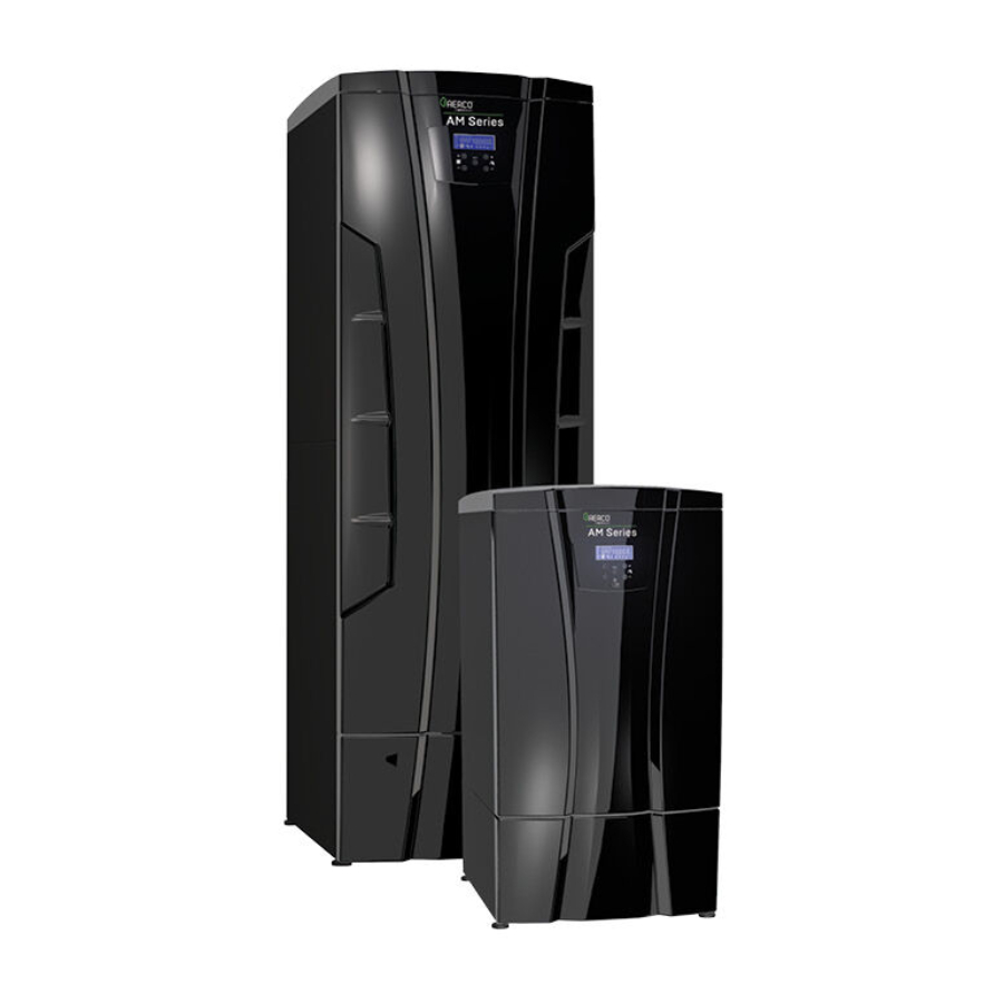
AM Series Boiler
AERCO International, Inc. • 100 Oritani Dr. • Blauvelt, NY 10913
Ph.: 800-526-0288
AM Series Heat Exchanger Module
TID-0137_0A
Page 1 of 36
01/18/2015
Advertisement
Table of Contents

Related Manuals for Aerco AM Series


Summary of Contents for Aerco AM Series
- Page 1 Water Heaters: • AM 399W • AM 500W • AM 750W • AM 1000W AM Series Heat Exchanger Module Revised: 01/18/2015 AERCO International, Inc. • 100 Oritani Dr. • Blauvelt, NY 10913 TID-0137_0A Page 1 of 36 Ph.: 800-526-0288 01/18/2015...
-
Page 2: Table Of Contents
The information contained in this document is subject to change without notice from AERCO International, Inc. AERCO makes no warranty of any kind with respect to this material, including, but not limited to, implied warranties of merchantability and fitness for a particular application. -
Page 3: Material And Tool Requirements
Wrench (10mm) Gasket x2 (1-1/4” Dia.) Gasket (3/4” Dia.) (P/N 60701007) (P/N 607001006) Gasket Gasket Air Compressor (P/N 60702097) (P/N 60702096) AERCO International, Inc. • 100 Oritani Dr. • Blauvelt, NY 10913 TID-0137_0A Page 3 of 36 Ph.: 800-526-0288 02/02/2015... - Page 4 Refer to the notes in the instructions for specific instructions. AERCO International, Inc. • 100 Oritani Dr. • Blauvelt, NY 10913 TID-0137_0A Page 4 of 36 Ph.: 800-526-0288...
-
Page 5: Preliminary Preparation Of The Unit
6. Once all the burner indicator icons are showing in the display, turn the boiler power switch to OFF, as this means all automatic valves are now locked in the open position. AERCO International, Inc. • 100 Oritani Dr. • Blauvelt, NY 10913 TID-0137_0A Page 5 of 36 Ph.: 800-526-0288... -
Page 6: Closing Water And Gas Connections
3. Completely remove power from the unit by shutting off electrical power upstream from the boiler. WARNING! High voltages are used in AM Series systems. It is required that all power applied to these boilers is removed first before performing any of the procedures described in this document. Use extreme care when accessing circuits and electrical connections within the equipment. -
Page 7: Draining Water From The Unit
CAUTION! Monitor the AM Series relief valve so as not to release too much pressure from the air compressor into the unit or the pressure relief valve might be tripped. -
Page 8: Removing The Covers
Top Cover “B” Front Cover Screws (2 each) “C” Front Cover “D” Bottom Cover Figure 2-6: Removing the Top and Front Covers AERCO International, Inc. • 100 Oritani Dr. • Blauvelt, NY 10913 TID-0137_0A Page 8 of 36 Ph.: 800-526-0288 02/02/2015... -
Page 9: Disconnecting Cables And Wiring Connections
1. Unscrew the Phillips head screw from the gas valve connector but leave it plugged in for now. See Figure 2-8. 2. To the right of the blower, cut the cable tie that ties the cables together. See Figure 2-8. AERCO International, Inc. • 100 Oritani Dr. • Blauvelt, NY 10913 TID-0137_0A Page 9 of 36 Ph.: 800-526-0288... - Page 10 11. Disconnect cable from the flame detector terminal on left side of blower flange. BURNER FLANGE BLOWER Figure 2-9: Cable Harness Disassembly AERCO International, Inc. • 100 Oritani Dr. • Blauvelt, NY 10913 TID-0137_0A Page 10 of 36 Ph.: 800-526-0288 02/02/2015...
- Page 11 Figure 2-11: Draping Cables and Harnesses onto Panel Door 13. This ends the wire harness preparation. Proceed to the next section for disassembly of the heat exchanger from the unit. AERCO International, Inc. • 100 Oritani Dr. • Blauvelt, NY 10913 TID-0137_0A Page 11 of 36 Ph.: 800-526-0288...
-
Page 12: Removing The Heat Exchanger
4. Carefully remove the entire blower/burner assembly from the heat exchanger, as shown in Figure 3-2. BURNER/BLOWER ASSEMBLY HEAT EXCHANGER Figure 3-2: Removing the Blower/Burner Assembly from the Heat Exchanger AERCO International, Inc. • 100 Oritani Dr. • Blauvelt, NY 10913 TID-0137_0A Page 12 of 36 Ph.: 800-526-0288 02/02/2015... - Page 13 (NOT PRESENT ON LOWEST HEAT EXCHANGER) STEP 5: REMOVE LOWER IGNITER ASSEMBLY Figure 3-3: Removing Lower Igniter, Flow Sensor, and Brackets AERCO International, Inc. • 100 Oritani Dr. • Blauvelt, NY 10913 TID-0137_0A Page 13 of 36 Ph.: 800-526-0288 02/02/2015...
- Page 14 EXCHANGER LOWER EDGE TO COVER OPENING. ENSURE ALL LOWER COMPONETS ARE COMPLETELY COVERED Figure 3-5: Placing Protective Plastic over Lower Components AERCO International, Inc. • 100 Oritani Dr. • Blauvelt, NY 10913 TID-0137_0A Page 14 of 36 Ph.: 800-526-0288 02/02/2015...
- Page 15 SUPPLY NUT AT THE REAR OF THE UNIT WITH 46mm WRENCH. Figure 3-7: Loosening the Water Supply Nut at Rear of Unit AERCO International, Inc. • 100 Oritani Dr. • Blauvelt, NY 10913 TID-0137_0A Page 15 of 36 Ph.: 800-526-0288...
- Page 16 WITH 19” LONG LONG 10mm NUT 10mm NUT DRIVER. DRIVER. Figure 3-9: Removing and Loosening Bolts Affixing Heat Exchanger to Rear Panel AERCO International, Inc. • 100 Oritani Dr. • Blauvelt, NY 10913 TID-0137_0A Page 16 of 36 Ph.: 800-526-0288 02/02/2015...
- Page 17 Figure 3-11: Removing Heat Exchanger from the Unit NOTE Retain the O-Ring (Figure 3-12) from the flow meter connection, for later reassembly, during removal of the heat exchanger. AERCO International, Inc. • 100 Oritani Dr. • Blauvelt, NY 10913 TID-0137_0A Page 17 of 36 Ph.: 800-526-0288...
- Page 18 21. Remove the lower smaller flue gasket, as shown in Figure 3-14, and replace if necessary. STEP 20: REMOVE FLUE GASKET STEP 21: REMOVE CONDENSATE DRAIN GASKET Figure 3-14: Removing the Two Gaskets from the Flue AERCO International, Inc. • 100 Oritani Dr. • Blauvelt, NY 10913 TID-0137_0A Page 18 of 36 Ph.: 800-526-0288 02/02/2015...
-
Page 19: Installing The Heat Exchanger
STEP 3: STEP 4: INSTALL INSTALL FLUE CONDENSATE DRAIN GASKET GASKET Figure 4-2: Fitting the Gaskets Securely Inside and Outside the Flange AERCO International, Inc. • 100 Oritani Dr. • Blauvelt, NY 10913 TID-0132_99 Page 19 of 36 Ph.: 800-526-0288 12/09/2014... - Page 20 Step 5 only applies if the heat exchanger is being serviced but NOT replaced. Figure 4-4: Draining Excess Water from the Heat Exchanger AERCO International, Inc. • 100 Oritani Dr. • Blauvelt, NY 10913 TID-0132_99 Page 20 of 36 Ph.: 800-526-0288...
- Page 21 STEP 7: PIECE OF WOOD Figure 4-6: Wood Position for Installing Heat Exchanger AERCO International, Inc. • 100 Oritani Dr. • Blauvelt, NY 10913 TID-0132_99 Page 21 of 36 Ph.: 800-526-0288 01/18/2015...
- Page 22 9. Insert the new heat exchanger into the unit, as shown in Figure 4-8, ensuring that the piece of wood underneath retains its position. Figure 4-8: Installing the Heat Exchanger into the Unit AERCO International, Inc. • 100 Oritani Dr. • Blauvelt, NY 10913 TID-0132_99 Page 22 of 36 Ph.: 800-526-0288...
- Page 23 10mm bolts on the rear panel of the unit, as shown in Figure 4-10. Figure 4-10: Slipping the Heat Exchanger Mounting Slots Under the Loose Bolts AERCO International, Inc. • 100 Oritani Dr. • Blauvelt, NY 10913 TID-0132_99 Page 23 of 36 Ph.: 800-526-0288...
- Page 24 This instruction only applies if the heat exchanger is being serviced but NOT replaced. Figure 4-12: Removing the Old Water Supply Inlet Gasket AERCO International, Inc. • 100 Oritani Dr. • Blauvelt, NY 10913 TID-0132_99 Page 24 of 36 Ph.: 800-526-0288 01/18/2015...
- Page 25 BEFORE APPLYING NUT. CONNECT WATER RETURN PIPING NUT TO FLOW METER CONNECTION HAND TIGHTEN ONLY! Figure 4-14: Reconnecting Water Return Piping AERCO International, Inc. • 100 Oritani Dr. • Blauvelt, NY 10913 TID-0132_99 Page 25 of 36 Ph.: 800-526-0288 01/18/2015...
- Page 26 STEP 19: TIGHTEN WATER SUPPY CONNECTION STEP 20: TIGHTEN WATER RETURN CONNECTION Figure 4-16: Wrench Tightening the Water Supply and Water Return Nuts AERCO International, Inc. • 100 Oritani Dr. • Blauvelt, NY 10913 TID-0132_99 Page 26 of 36 Ph.: 800-526-0288 01/18/2015...
- Page 27 STEP 27: POWER PESSURE CONN. SENSOR STEP GRND WIRE STEP 24: IGNITER CABLES Figure 4-18: Install Lower Igniter and Make Connections AERCO International, Inc. • 100 Oritani Dr. • Blauvelt, NY 10913 TID-0132_99 Page 27 of 36 Ph.: 800-526-0288 01/18/2015...
- Page 28 UPPER IGNITER STEP 33: CONNECT IGNITER CABLES TO IGNITER TERMINALS Figure 4-20: Install Upper Igniter and Connect Igniter Cables to Terminals AERCO International, Inc. • 100 Oritani Dr. • Blauvelt, NY 10913 TID-0132_99 Page 28 of 36 Ph.: 800-526-0288 01/18/2015...
-
Page 29: Final Reassembly
WITH BLUE UNTIL .… WIRE REMAINS ON RIGHT SIDE OF HEAT EXCHANGER Figure 5-2: Initial Arrangement and Routing of Smaller Harness AERCO International, Inc. • 100 Oritani Dr. • Blauvelt, NY 10913 TID-0132_99 Page 29 of 36 Ph.: 800-526-0288 01/18/2015... - Page 30 See Figure 5-4. STEP 7: SUPPLY SENSOR SUPPLY (PURPLE) PIPING Figure 5-4: Supply Sensor Connection AERCO International, Inc. • 100 Oritani Dr. • Blauvelt, NY 10913 TID-0132_99 Page 30 of 36 Ph.: 800-526-0288 01/18/2015...
-
Page 31: Installing The Larger Wiring Harness
GAS VALVE CONNECTOR STEP 3: FLAME DETECTOR STEP 4: HIGH LIMIT THERMOSTAT Figure 5-6: Larger Harness – Left Side Cable Connections AERCO International, Inc. • 100 Oritani Dr. • Blauvelt, NY 10913 TID-0132_99 Page 31 of 36 Ph.: 800-526-0288 01/18/2015... - Page 32 FAN CONN. (RED/ORG) STEP 10: MOTORIZED VALVE STEP 6: LOWER FAN CONN. (BLU/GRN) Figure 5-7: Larger Harness – Right Side Cable Connections AERCO International, Inc. • 100 Oritani Dr. • Blauvelt, NY 10913 TID-0132_99 Page 32 of 36 Ph.: 800-526-0288 01/18/2015...
-
Page 33: Turning On Services And Leak Testing
INLET CONN. INLET CONN. & HOSE & HOSE STEP 4: BLOWER COVER Figure 5-10: Installing the Air Inlet Connector/Hose and Blower Cover AERCO International, Inc. • 100 Oritani Dr. • Blauvelt, NY 10913 TID-0132_99 Page 33 of 36 Ph.: 800-526-0288 01/18/2015... -
Page 34: Turning On Water And Return To Service
5. Refer to Section 2.4, and by reversing the instructions, reinstall front, bottom, and top covers to the unit. 6. The AM unit may now be returned to service. AERCO International, Inc. • 100 Oritani Dr. • Blauvelt, NY 10913 TID-0132_99 Page 34 of 36 Ph.: 800-526-0288... - Page 35 AM Series Boiler Heat Exchanger Maintenance & Replacement Technical Instruction Document NOTES: AERCO International, Inc. • 100 Oritani Dr. • Blauvelt, NY 10913 TID-0132_99 Page 35 of 36 Ph.: 800-526-0288 01/18/2015...
- Page 36 AM Series Boiler Heat Exchanger Maintenance & Replacement Technical Instruction Document Change Log: Date Description Changed By 02/02/2015 Rev-0A: Release Curtis Harvey © AERCO International, Inc., 2011 AERCO International, Inc. • 100 Oritani Dr. • Blauvelt, NY 10913 TID-0132_99 Page 36 of 36 Ph.: 800-526-0288 01/18/2015...
Need help?
Do you have a question about the AM Series and is the answer not in the manual?
Questions and answers