Evolution A15TS Installation & Operation Manual
Auto cell cleaning model
Hide thumbs
Also See for A15TS:
- Installation and operation manual (12 pages) ,
- Installation and operation manual (12 pages)
Advertisement
Quick Links
INSTALLATION
& OPERATION MANUAL
Auto Cell Cleaning Model
With Timer: A15TS - A20TS - A25TS - A30TS - A35TS
No Timer: A15 - A20 - A25 - A30 - A35
27/30 Mudgeeraba Road, Worongary Queensland 4213
Phone 61 7 5565 0000 Fax 61 7 5565 0010
E. sales@evolutionwls.com.au
www.evolutionwls.com.au
Advertisement

Subscribe to Our Youtube Channel
Related Manuals for Evolution A15TS


Summary of Contents for Evolution A15TS
- Page 1 INSTALLATION & OPERATION MANUAL Auto Cell Cleaning Model With Timer: A15TS - A20TS - A25TS - A30TS - A35TS No Timer: A15 - A20 - A25 - A30 - A35 27/30 Mudgeeraba Road, Worongary Queensland 4213 Phone 61 7 5565 0000 Fax 61 7 5565 0010 E.
- Page 2 This system is designed for robust reliability and easy operation to give you many years of trouble free service. Please read the instructions thoroughly before operating your unit. If you have any concerns or require any further assistance, then please to not hesitate to contact our friendly staff or any of our Evolution distributors. Chemicals It is important to note that the Evolution Series chlorinator does not maintain the water chemistry of your swimming pool water;...
- Page 3 Cell Housing Installation The electrolytic cell housing must be plumbed into the return line after the filter. Please see the installation diagram, fig.1, below for the preferred method. If a heater is plumbed into the system then the cell housing must be installed after the heater in the return line to protect the elements or heat exchanger.
- Page 4 Functions Now that you have installed your Evolution power pack and cell correctly you can learn how to use it. All Evolution Series chlorinators are fitted with a 240v 10A power socket located on the right hand underside of the power pack.
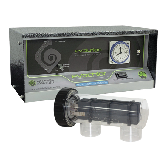
- Page 5 1. Chlorine Output LEDs – Fig.2 The output lights follow the curve of the distinguished Evolution logo. If the correct salt level is in the pool then all 10 lights will illuminate. Each light represents 10% chlorine output. If all lights are not illuminated then a higher salinity level will be required.
- Page 6 6. Circuit Breaker The circuit breaker mounted on the front right hand side of the Evolution chlorinator is designed to trip out in the event of power surge or overload. When tripped the yellow centre button will pop out shutting down the unit.
-
Page 7: Troubleshooting
TROUBLESHOOTING Fault/Problem Possible Cause Remedy NO FLOW Pump turned off Ensure pump is on - All chlorine output Valves closed Valves open LED’s flashing as per Air in system Check all o-rings and grease note 1. Page 4 Dirty filter/Blockage Clean or Backwash filter Low water level Fill up pool... - Page 8 Warranty Your Evolution Series Chlorinator is covered by a 3 year full warranty from the date of purchase. The power pack controller and electrolytic cell are covered against defects in materials and assembly from the date of purchase in a domestic application. All electrical or mechanical failure due to faulty components will be repaired or replaced at no cost to the owner, including labour.
- Page 9 NOTES...
- Page 10 NOTES...
- Page 11 27/30 Mudgeeraba Road, Worongary Queensland 4213 Phone 61 7 5565 0000 Fax 61 7 5565 0010 E. sales@evolutionwls.com.au www.evolutionwls.com.au...
Need help?
Do you have a question about the A15TS and is the answer not in the manual?
Questions and answers