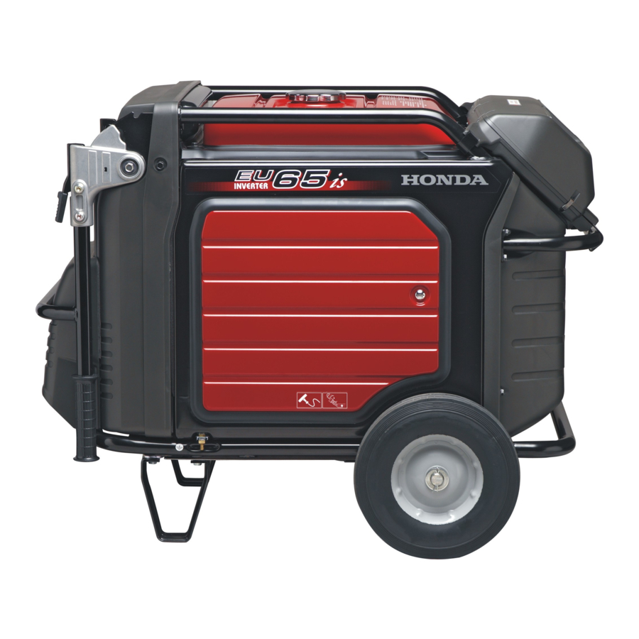
Honda EU65is Owner's Manual
Hide thumbs
Also See for EU65is:
- Service manual (437 pages) ,
- Owner's manual (78 pages) ,
- Owner's manual (22 pages)
Table of Contents
Advertisement
Advertisement
Table of Contents

Related Manuals for Honda EU65is


Summary of Contents for Honda EU65is
- Page 2 07/09/15 12:24:48 32Z25610_001 Honda EU65is OWNER’S MANUAL MANUEL DE L’UTILISATEUR BEDIENUNGSANLEITUNG MANUAL DE EXPLICACIONES...
- Page 3 07/09/15 12:24:50 32Z25610_002...
- Page 4 07/09/15 12:24:54 32Z25610_003 Honda EU65is OWNER’S MANUAL The‘‘e-SPEC’’mark symbolizes environmentally responsible technologies applied to Honda power equipment, which contains our wish to ‘‘preserve nature for generations to come.’’...
- Page 5 07/09/15 12:24:56 32Z25610_004...
- Page 6 All information in this publication is based on the latest product information available at the time of approval for printing. Honda Motor Co., Ltd. reserves the right to make changes at any time without notice and without incurring any obligation.
-
Page 7: Table Of Contents
. 39 MAINTENANCE ................40 TRANSPORTING/STORAGE ............53 TROUBLESHOOTING ............... 55 SPECIFICATIONS ................57 INSTALLATION OF KIT PARTS ............59 MAJOR Honda DISTRIBUTOR ADDRESSES ........ . 72 WIRING DIAGRAM ........74, inside of back cover... -
Page 8: Safety Instructions
07/09/15 12:25:15 32Z25610_007 SAFETY INSTRUCTIONS IMPORTANT SAFETY INFORMATION Honda generators are designed for use with electrical equipment that has suitable power requirements. Other uses can result in injury to the operator or damage to the generator and other property. Most accidents can be prevented if you follow all instructions in this manual and on the generator. - Page 9 07/09/15 12:25:22 32Z25610_008 Carbon Monoxide Hazards Exhaust contains poisonous carbon monoxide, a colorless, odorless gas. Breathing exhaust can cause loss of consciousness and may lead to death. If you run the generator in an area that is confined, or even partially enclosed area, the air you breathe could contain dangerous amount of exhaust gas.
- Page 10 07/09/15 12:25:29 32Z25610_009 Fire and Burn Hazards Do not use the generator in areas with a high risk of fire. When installed in ventilated rooms, additional requirements for fire and explosion protection shall be observed. The exhaust system gets hot enough to ignite some materials. −...
- Page 11 Do not throw it in the trash or pour it on the ground. An improperly disposed battery can hurt the environment. Always confirm local regulations for battery disposal. Contact your Honda servicing dealer for a replacement.
-
Page 12: Safety Label Locations
These labels warn you of potential hazards that can cause serious injury. Read the labels and safety notes and precautions described in this manual carefully. If a label comes off or becomes hard to read, contact your Honda dealer for a replacement. - Page 13 07/09/15 12:25:46 32Z25610_012 Honda generator is designed to give safe and dependable service if operated according to instructions. Read and understand the Owner’s Manual before operating the generator. Failure to do so could result in personal injury or equipment damage.
- Page 14 07/09/15 12:25:52 32Z25610_013 Stop the engine before refueling. Gasoline is extremely flammable and explosive under certain conditions. Refuel in a well ventilated area with the engine stopped. Keep away from cigarette, smoke and sparks when refueling the generator. Always refuel in a well-ventilated location. Wipe up spilled gasoline at once.
-
Page 15: Ce Mark And Noise Label Locations
07/09/15 12:25:56 32Z25610_014 CE mark and noise label locations NOISE LABEL AND CE MARK Manufacturer and address NOISE LABEL Year of manufacture Dry mass... -
Page 16: Component Identification
07/09/15 12:26:02 32Z25610_015 COMPONENT IDENTIFICATION CONTROL PANEL OIL ALERT INDICATOR (G, GW types) OVERLOAD INDICATOR i-MONITOR BUTTON OUTPUT INDICATOR AC CIRCUIT PROTECTORS i-MONITOR ENGINE SWITCH FUEL VALVE LEVER ECO THROTTLE SWITCH AC RECEPTACLES (F type) (IT type) AC CIRCUIT PROTECTORS AC CIRCUIT PROTECTORS AC RECEPTACLES AC RECEPTACLES... - Page 17 07/09/15 12:26:06 32Z25610_016 CONTROL PANEL (See page 8) FUEL GAUGE FUEL TANK CAP FUSE RIGHT MAINTENANCE (inside battery COVER maintenance cover) STARTER GRIP BATTERY (inside battery maintenance cover) BATTERY MAINTENANCE COVER OIL DRAIN BOLT OIL FILLER CAP/ DIPSTICK FOLDING HANDLES GROUND TERMINAL LEFT MAINTENANCE COVER...
- Page 18 07/09/15 12:26:10 32Z25610_017 FRAME SERIAL NUMBER Record the frame serial number in the space below. You will need this serial number when ordering parts. Frame serial number:...
- Page 19 07/09/15 12:26:15 32Z25610_018 Eco Throttle Engine speed is kept at idle automatically when the electrical appliance is disconnected and it returns to the proper speed by the electrical load when electrical appliance is connected. This position is recommended to minimize the fuel consumption while in operation. When high electrical load appliances is connected simultaneously, turn the Eco Throttle switch to the OFF position to reduce voltage changes.
- Page 20 07/09/15 12:26:20 32Z25610_019 AC Circuit Protectors The AC circuit protectors will automatically switch OFF if there is a short circuit or a significant overload of the generator at each receptacle. If an AC circuit protector switches OFF automatically, check that the appliance is working properly and does not exceed the rated load capacity of the circuit before resetting the AC circuit protector ON.
- Page 21 07/09/15 12:26:25 32Z25610_020 Indicators and i-Monitor OVERLOAD INDICATOR (RED) OUTPUT INDICATOR OIL ALERT INDICATOR (GREEN) (RED) i-MONITOR (BUTTON) i-MONITOR i-MONITOR (SINGLE DIGIT SCREEN) (FOUR DIGIT SCREEN) Output Indicator The output indicator (green) is illuminated when the generator is operating normally. It indicates that the generator is producing electrical power at the receptacles.
- Page 22 07/09/15 12:26:29 32Z25610_021 Oil Alert system The Oil Alert system is designed to prevent the engine damage caused by an insufficient amount of oil in the crankcase. Before the oil level in the crankcase can fall below a safe limit, the Oil Alert indicator comes on and the Oil Alert system automatically will stop the engine (the engine switch will remain in the ON position).
- Page 23 07/09/15 12:26:36 32Z25610_022 i-Monitor The i-Monitor is a user interface that allows the operator to view (when the generator is running) total operating time in hours, generator output, engine RPM, battery voltage and error messages. The different display modes are selected by pressing the i-Monitor button. i-Monitor at Start Up During start up, the i-Monitor display and all three indicators will simultaneously blink once.
- Page 24 07/09/15 12:26:43 32Z25610_023 i-Monitor Display Mode 1 − Total Operating Hours This mode displays the total operating hours of the generator. When the generator is running, the total operating time accumulates. If the total operating time is less than one hour, the numeric display will be ‘‘0.’’...
- Page 25 Have the battery recharged and checked (see pages thru. i-Monitor System Error Messages If the generator has a system malfunction, it will show an error message on the i-Monitor display. If an error message displays, contact an authorized Honda generator dealer. OVERLOAD INDICATOR ERROR MESSAGE (Example: E-01)
- Page 26 07/09/15 12:26:56 32Z25610_025 Folding Handle The foldable handle is intended for ease of transportation and should be folded when the generator is stationary. Do not rest objects on the extended handle. To Extend The Handle Lift handle upward. Lock levers will lock and secure the handle into place.
- Page 27 07/09/15 12:27:07 32Z25610_026 Maintenance Covers Open and close the maintenance cover for maintenance of the your generator. Open the maintenance cover, too, to use the recoil starter when the battery is discharged. Be sure to close the maintenance cover while the generator is running.
-
Page 28: Pre-Operation Check
07/09/15 12:27:13 32Z25610_027 PRE-OPERATION CHECK Be sure to check the generator on a level surface with the engine stopped. Check the engine oil level. Using non detergent oil or 2-stroke engine oil could shorten the engine’s service life. Use high-detergent, premium quality 4-stroke engine oil, certified to meet or exceed U.S. - Page 29 07/09/15 12:27:18 32Z25610_028 Open the right maintenance cover. Remove the oil filler cap, and wipe the dipstick with a clean rag. Check the oil level by inserting the dipstick in the filler hole without screwing it in. If the oil level is below the end of the dipstick, refill with recommended oil up to the top of the oil filler neck.
- Page 30 07/09/15 12:27:26 32Z25610_029 Check the fuel level. If the fuel level is low, remove the fuel tank cap and refill. Do not overfill. After refueling, tighten the fuel tank cap securely. Use automotive unleaded gasoline with a Research Octane Number of 91 or higher (a Pump Octane Number of 86 or higher).
- Page 31 Gasolines containing alcohol If you decide to use a gasoline containing alcohol (gasohol), be sure it’s octane rating is at least as high as that recommended by Honda. There are two types of ‘‘gasohol’’: one containing ethanol, and the other containing methanol.
- Page 32 07/09/15 12:27:45 32Z25610_031 Check the air cleaner. Open the left maintenance cover. Loosen the cover screws and remove the air cleaner cover. Remove the air cleaner element from the air cleaner cover. Check the air cleaner element to be sure it is clean and in good condition.
-
Page 33: Starting The Engine
07/09/15 12:27:51 32Z25610_032 STARTING THE ENGINE When starting the generator after adding fuel for the first time, after long-term storage, or after running out of fuel, turn the fuel valve lever to the ‘‘ON’’ position, then wait for 10 to 20 seconds before starting the engine. - Page 34 07/09/15 12:27:58 32Z25610_033 Make sure the Eco Throttle switch is in the OFF position, or more time will be required for warm up. ECO THROTTLE SWITCH Turn the engine switch to the START position and hold it there until the engine starts. Use the recoil starter when the battery voltage is too low to turn the starter motor (see page ENGINE SWITCH...
- Page 35 07/09/15 12:28:04 32Z25610_034 Use the recoil starter when the battery voltage is too low to turn the starter motor. Turn the engine switch to the ON position. ENGINE SWITCH Open the right maintenance cover by turning its latch counterclockwise. Pull the starter grip lightly until you feel resistance, then pull briskly in the direction of the arrow as shown below.
- Page 36 07/09/15 12:28:10 32Z25610_035 The starter rope can be drown back very quickly before you release it. This may pull your hand forcefully toward the engine and cause an injury. Do not exceed 20 degrees from horizontal when pulling the starter grip. Do not allow the starter grip to snap back against the engine.
-
Page 37: High Altitude Operation
If you always operate the generator at altitudes higher than 1,500-meter (5,000 feet) above sea level, have your authorized Honda dealer perform these carburetor modifications. Even with suitable carburetor jetting, engine horsepower will decrease approximately 3.5% for each 300-meter (1,000-foot) increase in altitude. -
Page 38: Generator Use
07/09/15 12:28:19 32Z25610_037 GENERATOR USE Be sure to ground the generator when the connected equipment is grounded. Do not connect to a building’s electrical system unless an isolation switch has been installed by a qualified electrician. Connections for standby power to a building’s electrical system must be made by a qualified electrician and must comply with all applicable laws and electrical codes. - Page 39 07/09/15 12:28:27 32Z25610_038 Do not exceed the current limit specified for any one receptacle. Do not connect the generator to a household circuit. This could cause the damage to the generator or to electrical appliances in the house. Do not modify or use the generator for other purposes than it is intended for.
- Page 40 07/09/15 12:28:33 32Z25610_039 AC applications Start the engine and make sure the output indicator (green) comes Confirm that the appliance to be used is switched off, and plug in the appliance. OUTPUT INDICATOR Substantial overloading that continuously lights the Overload indicator (red) may damage the generator.
- Page 41 When an electric motor is started, both the Overload indicator (red) and the Output indicator (green) may go on simultaneously. This is normal if the Overload indicator (red) goes off after about five (5) seconds. If the Overload indicator (red) stays on, consult your Honda generator dealer.
- Page 42 07/09/15 12:28:45 32Z25610_041 AC Circuit Protector The AC circuit protectors will automatically switch OFF (push button comes out) if there is a short circuit or a significant overload of the generator at receptacle. If an AC circuit protector switches OFF automatically, check that the appliance is working properly and does not exceed the rated load capacity of the circuit before resetting the AC circuit protector ON (pushing the push button in).
- Page 43 07/09/15 12:28:49 32Z25610_042 F type CIRCUIT PROTECTOR CIRCUIT PROTECTOR (For receptacle No. 2) (For receptacle No. 3) AC RECEPTACLE AC RECEPTACLE AC RECEPTACLE No. 1 No. 2 No. 3 IT type CIRCUIT PROTECTOR CIRCUIT PROTECTOR (For receptacle No. 2) (For receptacle No. 3) AC RECEPTACLE AC RECEPTACLE AC RECEPTACLE...
-
Page 44: Stopping The Engine
07/09/15 12:28:55 32Z25610_043 STOPPING THE ENGINE To stop the engine in an emergency, turn the engine switch to the OFF position. IN NORMAL USE: Switch off the connected equipment and pull off the inserted plug. Turn the engine switch to the OFF position. ENGINE SWITCH Turn the fuel valve lever to the OFF position. -
Page 45: Maintenance
Service more frequently when used in dusty areas. These items should be serviced by your servicing dealer, unless you have the proper tools and are mechanically proficient. Refer to Honda shop manual for service procedures. For commercial use, log hours of operation to determine proper maintenance intervals. - Page 46 07/09/15 12:29:18 32Z25610_045 CHANGING OIL Drain the oil while the engine is still warm to assure rapid and complete draining. Open the right maintenance cover and remove the oil drain hole cover. Remove the oil filler cap and oil drain plug to drain the oil. Install the oil drain plug, and tighten it securely.
- Page 47 07/09/15 12:29:24 32Z25610_046 AIR CLEANER SERVICE A dirty air cleaner will restrict air flow to the carburetor. To prevent carburetor malfunction, service the air cleaner regularly. Service more frequently when operating the generator in extremely dusty areas. Do not use gasoline or low flash point solvents for cleaning. They are flammable and explosive under certain conditions.
- Page 48 07/09/15 12:29:31 32Z25610_047 Clean the air cleaner element in warm soapy water, rinse, and allow to dry thoroughly, or clean in non-flammable solvent and allow to dry. AIR CLEANER ELEMENT Dip the air cleaner element in clean engine oil, then squeeze out all excess oil.
- Page 49 07/09/15 12:29:40 32Z25610_048 FUEL SEDIMENT CUP SERVICE Gasoline is extremely flammable and is explosive under certain conditions. Do not smoke or allow flames or sparks in the area. You can be burned or seriously injured when handling fuel. Stop the engine and keep heat, sparks, and flame away. Handle fuel only outdoors.
- Page 50 07/09/15 12:29:48 32Z25610_049 SPARK PLUG SERVICE RECOMMENDED SPARK PLUG: BPR5ES (NGK) W16EPR-U (DENSO) To ensure proper engine operation, the spark plug must be properly gapped and free of deposits. Open the left maintenance cover. Loosen the cover screw and remove the spark plug inspection cover. SPARK PLUG INSPECTION COVER COVER SCREW...
- Page 51 07/09/15 12:29:55 32Z25610_050 Visually inspect the spark plug. Discard it if the insulator is cracked or chipped. Clean the spark plug with a wire brush if it is to be reused. Measure the plug gap with a feeler gauge. Correct as necessary by carefully bending the side electrode. The gap should be: −...
- Page 52 07/09/15 12:30:03 32Z25610_051 SPARK ARRESTER CLEANING If the engine has been running, the muffler will be very hot. Allow the muffler to cool before servicing the spark arrester. Remove the two 5 × 14 mm pan head screws, and remove the tail pipe and spark arrester.
- Page 53 In the event of fuse failure, locate the cause of failure and repair before you continue operation. If the fuse continues to fail, discontinue generator use and consult an authorized Honda generator dealer. Turn the engine switch OFF and remove the key before checking or replacing the fuse.
- Page 54 07/09/15 12:30:15 32Z25610_053 Remove the fuse holder cover and pull the fuse out. Replace the fuse with a fuse of the same type and rating. Specified fuse: 1A, 15A FUSE (15 A) FUSES (1 A) FUSE HOLDER COVER If frequent fuse failure occurs, determine the cause and correct the problem before attempting to operate the generator further.
- Page 55 07/09/15 12:30:25 32Z25610_054 BATTERY REMOVAL/INSTALLATION Batteries produce explosive gases: If ignited, and explosion can cause serious injury or blindness. Provide adequate ventilation when charging. CHEMICAL HAZARD: Battery electrolyte contains sulfuric acid. Contact with eyes or skin, even through clothing, may cause severe burns.
- Page 56 07/09/15 12:30:31 32Z25610_055 Remove the negative ( ) cable from the battery negative ( ) − − terminal, then remove the positive ( ) cable from the battery + positive ( ) terminal. + Unhook the battery holder band from the bottom hook of the generator.
- Page 57 07/09/15 12:30:43 32Z25610_056 Installation: Make sure that the engine switch is turned OFF. Install the battery. Connect the battery positive ( ) cable to the + battery positive ( ) terminal, then the battery negative ( ) cable to + −...
-
Page 58: Transporting/Storage
07/09/15 12:30:51 32Z25610_057 TRANSPORTING/STORAGE To prevent fuel spillage when transporting or during temporary storage, the generator should be secured upright in its normal operating position, with the engine switch OFF. The fuel valve lever should be turned OFF. When transporting the generator: Do not overfill the tank. - Page 59 07/09/15 12:31:02 32Z25610_058 Before storing the unit for an extended period: Be sure the storage area is free of excessive humidity and dust. Drain the fuel. Gasoline is extremely flammable and is explosive under certain conditions. Perform this task in a well ventilated area with the engine stopped.
-
Page 60: Troubleshooting
To check: If the engine still Turn off the fuel valve does not start, lever and loosen the take the drain screw. generator to an Turn on the fuel valve authorized lever. Fuel should flow Honda dealer. from the drain. - Page 61 Turn the AC protector ON? circuit protector Is the Output indicator ON? Take the Is the Overload generator to an indicator ON? authorized Honda dealer. Check the Take the electrical NO DEFECTS generator to an appliance or authorized equipment for Honda dealer.
-
Page 62: Specifications
07/09/19 14:52:17 32Z25610_061 SPECIFICATIONS Dimensions and Weight Model EU65is Description code EASJ Length 850 mm (33.5 in) [extended handle] 1,195 mm (47.0 in) Width 672 mm (26.5 in) Height 699 mm (27.5 in) [extended handle] 716 mm (28.2 in) Dry mass [weight] 115.0 kg (253.5 lbs) - Page 63 07/09/15 12:31:45 32Z25610_062 Noise Model EU65is Type G, GW, F, IT Sound pressure level (Lp ) 75 dB (A) According to 98/37/EC Microphone point CONTROL PANEL Center 1.60 m 1.0 m Guaranteed sound power level 89 dB (A) ) Tested by 2000/14/EC at Eco Throttle Switch turn on ‘‘the figures quoted are emission levels and are not necessarily safe...
-
Page 64: Installation Of Kit Parts
07/09/15 12:31:51 32Z25610_063 INSTALLATION OF KIT PARTS SAFETY The Importance of Proper Assembly Proper assembly is essential to operator safety and the reliability of the machine. Any error or oversight made by the person assembling and servicing a unit can easily result in faulty operation, damage to the machine, or injury to the operator. - Page 65 07/09/15 12:31:57 32Z25610_064 Important Safety Precautions Make sure you have a clear understanding of all basic shop safety practices and that you are wearing appropriate clothing and safety equipment. When performing this assembly, be especially careful of the following: □ Read the instructions before you begin and be sure you have the tools and skills required to perform the tasks safely.
- Page 66 07/09/15 12:32:05 32Z25610_065 STANDARD KIT PARTS Loose Parts Check all loose parts against the following list. Contact your dealer if any of the loose parts shown below are not included with your generator. Ref. No. Description Qty. Ref. No. Description Qty.
- Page 67 07/09/15 12:32:13 32Z25610_066 Wheel Kit Installation Do not operate the generator without the wheel kit installed. The wheel kit provides an air space between the ground and the generator air intake. If the wheel kit is not installed, it may be possible for dirt and debris to be drawn into the generator air intake causing possible generator damage.
- Page 68 07/09/15 12:32:20 32Z25610_067 Handle Installation Install the handle assembly on the generator upper frame using the 12 mm washers, spring washers and handle holder bolts. TORQUE: 20 23 N·m (2.0 2.3 kgf·m , 14 17 lbf·ft) − − − HANDLE HOLDER BOLT (2) SPRING WASHER (2) 12 mm WASHER (2) HANDLE...
- Page 69 07/09/15 12:32:24 32Z25610_068 Rear Bar Installation Install the rear bar on the generator frame using the two 6 × 30 mm flange bolts and two cap nuts. TORQUE: 9 13 N·m (0.9 1.3 kgf·m , 6.5 9 lbf·ft) − − −...
- Page 70 07/09/15 12:32:31 32Z25610_069 Battery WARNING: Battery posts, terminals and related accessories contain lead and lead compounds. Wash hands after handling. The battery is disconnected and strapped into the battery tray for shipment. Remove the battery maintenance cover (see page Remove the battery strap from the bottom hook, and then remove the battery.
- Page 71 07/09/15 12:32:35 32Z25610_070 Remove the protective cover from the battery positive ( ) terminal, + connect the red cable to the battery positive ( ) terminal. + Connect the black cable to the battery negative ( ) terminal. − Secure the battery by hooking the strap onto the bottom hook of the generator.
- Page 72 07/09/15 12:32:41 32Z25610_071 OPTIONAL KIT PARTS Remote Control Kit Remove the battery maintenance cover (see page Remove the plug from the 6-pin connector. PLUG 6-PIN CONNECTOR View the back of the battery maintenance cover and locate the knockout near the top center of the cover. Carefully remove the knockout.
- Page 73 07/09/15 12:32:49 32Z25610_072 Pass the remote control cable through the supplied wire grommet and fit the grommet into the battery maintenance cover knockout. Plug the remote control cable into the 6-pin connector. Install the battery maintenance cover and tighten the cover screw. REMOTE CONTROL CABLE GROMMET REMOTE CONTROL...
- Page 74 07/09/15 12:32:55 32Z25610_073 Starting the engine with remote control: Turn the fuel valve lever to the ON position. Turn the engine switch to the REMOTE (far left) position. ENGINE SWITCH FUEL VALVE LEVER Press and hold the start button until the engine pilot lamp illuminates.
- Page 75 07/09/15 12:33:01 32Z25610_074 Stopping the engine: Press the stop button. STOP BUTTON Turn the engine switch to the OFF position. Turn the fuel valve lever to the OFF position. ENGINE SWITCH FUEL VALVE LEVER...
- Page 76 07/09/15 12:33:08 32Z25610_075 Hanger Kit Protect the fuel tank and frame pipe with the protector films during installation of the hanger. Insert the bracket installation part at one end of the hanger into the clearance between the frame pipe and fuel tank. Slide the hanger and insert another bracket installation part of the hanger into the gap between the frame pipe and fuel tank on the other side.
-
Page 77: Major Honda Distributor Addresses
Honda Power Equipment Sweden AB Västkustvägen 17 Tel: 040-600 23 00 202 15 Malmö, Fax: 040-600 23 19 Sweden Honda Produtos De Força, Portugal, S.A. Lugar da Abrunheira Tel: 351-1-9150374 S. Pedro de Penaferrim Fax: 351-1-9111021 2710 Sintra, Portugal Berema A/S... - Page 78 07/09/15 12:33:47 32Z25610_077 NAME OF FIRM (COMPANY) ADDRESS TEL: FAX: OY Brandt AB Tuupakantie 4 Tel: 90-895-501 SF-01740, Vantaa Fax: 90-878-5276 Finland TIMA PRODUCTS A/S Tårnfalkevej 16, Postboks 511 Tel: 31-49-17-00 DK 2650 Hvidovre Fax: 36-77-16-30 Denmark Greens Polig. Industrial Congost Tel: 93-871-84-50 08530, La Garriga Fax: 93-871-81-80...
-
Page 79: Wiring Diagram
07/09/15 12:33:54 32Z25610_078 WIRING DIAGRAM ABBREVIATIONS Symbol Part name Symbol Part name ACCP Ac Circuit Protector Inverter Unit ACOR AC Output Receptacle Inverter Unit Block Battery (IT) IT Type Choke Control Motor Master Winding Control Panel Block Oil Alert Indicator Diode Overload Indicator EcoSw... - Page 80 07/09/15 12:34:01 32Z25610_079 SWITCH CONNECTIONS ENGINE SWITCH REMOTE START ECOTHROTTLE SWITCH COM (-)
- Page 81 07/09/15 12:34:02 32Z25610_080...
Need help?
Do you have a question about the EU65is and is the answer not in the manual?
Questions and answers